Table of Contents
Advertisement
Quick Links
MP114E
U-624 Rotation Stage
User Manual
Version: 1.1.0
Physik Instrumente (PI) GmbH & Co. KG, Auf der Roemerstrasse 1, 76228 Karlsruhe, Germany
Phone +49 721 4846-0, Fax +49 721 4846-1019, Email info@pi.ws, www.pi.ws
Date: 31.07.2020
This document describes the following product:
U-624.03
PILine® rotation stage, small design, >360°
rotation range, velocity 720°/s, incremental
encoder, 35 µrad resolution, 28,5 mm
diameter, piezoelectric ultrasonic motor
Advertisement
Table of Contents

Related Manuals for PI U-624


Summary of Contents for PI U-624
- Page 1 720°/s, incremental encoder, 35 µrad resolution, 28,5 mm diameter, piezoelectric ultrasonic motor Physik Instrumente (PI) GmbH & Co. KG, Auf der Roemerstrasse 1, 76228 Karlsruhe, Germany Phone +49 721 4846-0, Fax +49 721 4846-1019, Email info@pi.ws, www.pi.ws...
- Page 2 The patents held by PI are found in our patent list: https://www.physikinstrumente.com/en/about-pi/patents © 2020 Physik Instrumente (PI) GmbH & Co. KG, Karlsruhe, Germany. The text, photographs and drawings in this manual are protected by copyright. With regard thereto, Physik Instrumente (PI) GmbH & Co. KG retains all the rights.
-
Page 3: Table Of Contents
ID Chip ......................10 Unpacking Installation General Notes on Installation ................... 13 Mounting the U-624 onto an Underlying Surface and Connecting it to a Protective Earth Conductor ..................15 Fixing the Load to the U-624 ..................17 Starting and Operating General Notes on Starting and Operating .............. - Page 4 Maintenance General Notes on Maintenance ................25 Doing a Maintenance Run ..................25 Cleaning the U-624 ....................25 Troubleshooting Customer Service Technical Data 10.1 Specifications ......................31 10.1.1 Data Table ....................31 10.1.2 Reference Switch Specifications ..............32 10.1.3 Maximum Ratings ..................32 10.2 Ambient Conditions and Classifications ..............
-
Page 5: About This Document
Downloading Manuals ........................3 Objective and Target Audience of this User Manual This user manual contains the information required for using the U-624 as intended. It assumes that the reader has a fundamental understanding of basic servo systems as well as motion control concepts and applicable safety procedures. -
Page 6: Definition Of Terms
Figures For better understandability, the colors, proportions, and degree of detail in illustrations can deviate from the actual circumstances. Photographic illustrations may also differ and must not be seen as guaranteed properties. Version: 1.1.0 MP114E U-624 Rotation Stage... -
Page 7: Other Applicable Documents
Contact our customer service department (p. 29). Downloading manuals 1. Open the website www.pi.ws. 2. Search the website for the product number (e.g., U-624) or the product family (e.g., PILine®). 3. Click the corresponding product to open the product detail page. -
Page 9: Safety
Organizational Measures ....................... 6 Intended Use The U-624 is a laboratory device as defined by DIN EN 61010-1. It is intended for indoor use and use in an environment that is free of dirt, oil and lubricants. In accordance with its design, the U-624 is intended for single-axis positioning, adjustment and rotation of loads at different velocities in interval operation. -
Page 10: Organizational Measures
Add all information from the manufacturer to the user manual, for example supplements or technical notes. If you give the U-624 to a third party, include this user manual as well as other relevant information provided by the manufacturer. -
Page 11: Product Description
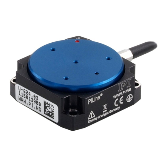
Figure 1: U-624 product view Base body 0° mark: After a reference move of the U-624, the red dot on the motion platform is above the 0 mark in the base body. Motion platform Cable for connecting to the controller The arrow in the figure shows the positive direction of motion. -
Page 12: Product Labeling
3 Product Description Product Labeling Figure 2: U-624: Position of the product labeling (example view) Position Labeling Description U-624.03 Product name 123456789 Serial number (example), individual for each U-624 Meaning of each position (from the left): 1 = internal information... -
Page 13: Scope Of Delivery
PILine® rotation stage, small design, >360° rotation range, velocity 720°/s, incremental encoder, 35 µrad resolution, 28,5 mm diameter, piezoelectric ultrasonic motor 1474 4 socket head screws M2x10, ISO 4762, for mounting the U-624 3109 Hex key, AF 1.5 MP121EK Short instructions for PILine® positioners... -
Page 14: Accessories
Refer to the controller user manual and/or associated software manuals for the commands that make use of the reference point signal. The red dot on the platform is above the 0° mark in the base body after the U-624 has done a reference move. -
Page 15: Unpacking
4 Unpacking Unpacking 1. Unpack the U-624 with care. 2. Compare the contents with the scope of delivery according to the contract and the delivery note. 3. Inspect the contents for signs of damage. If any parts are damaged or missing, contact our customer service department (p. -
Page 17: Installation
NOTICE Lubricants, dirt, condensation! Dirt, oil, lubricants and condensation will render the motor/drive inoperable. Ensure that the piezo motor of the U-624 does not come into contact with lubricants. Keep the U-624 free from dirt and condensation. NOTICE Heating up of the U-624 during operation! The heat produced during operation of the U-624 can affect your application. - Page 18 The platform could move unexpectedly if the load exceeds the rotation stage's drive torque when the U-624 is mounted vertically (e.g., due to pulling forces on the cable of the load). Unwanted changes in the position of the platform can damage the drive, the load or the surroundings.
-
Page 19: Mounting The U-624 Onto An Underlying Surface And Connecting It To A Protective Earth Conductor
Incorrect mounting can warp the base body. A warped base body will increase wear and reduce accuracy. Mount the U-624 onto a flat surface. The recommended flatness of the surface is 10 µm. For applications with large temperature changes: Only fix the U-624 to surfaces that have the same or similar thermal expansion properties as the U-624 (e.g., surfaces made of aluminum). - Page 20 Mounting the U-624 onto an underlying surface and connecting it to a protective earth conductor 1. Align the U-624 on the underlying surface so that the corresponding holes in the U-624 and underlying surface are in line. 2. Insert the three screws into the holes in the base body of the U-624.
-
Page 21: Fixing The Load To The U-624
NOTICE Impermissibly high forces and torques! Impermissibly high forces and torques that are applied to the platform can damage the U-624. For fixing type and mass of the load, pay attention to the maximum permissible forces according to the specifications (p. 31). - Page 22 Suitable tool for tightening the screws Fixing the load 1. Align the load on the U-624 so that the mounting holes in the load and the holes in the platform are in line. 2. Fix the load with at least three screws.
-
Page 23: Starting And Operating
If a protective earth conductor is not or not properly connected, dangerous touch voltages can occur on the U-624 in the case of malfunction or failure of the system. If there are touch voltages, touching the U-624 can result in minor injuries from electric shock. - Page 24 HINWEIS Short-circuiting due to condensation! Condensation can lead to short-circuiting and failure of the U-624. Wait for a sufficient period of time to allow the U-624 to reach room temperature in the following cases: − After unpacking or before starting for the first time If the U-624 has been brought from a cold into a warm environment or from a warm −...
- Page 25 Pay attention to the information in the "Motor Power" section (p. 34). INFORMATION Although the U-624 operates quietly in theory, noise levels of up to 50 dB (A) are possible during operation. The ultrasonic drive of the U-624 can also generate higher noise levels at frequencies between 100 and 500 kHz.
-
Page 26: Starting And Operating The U-624
If you use the software that is included in the scope of delivery of the controller (p. 9), the operating parameters of the U-624 can be loaded from a positioner database. The positioner database contains the default parameter values of your rotation stage for doing initial motion testing during starting. -
Page 27: Adjusting Parameter Values When Using Extension Cables
1. Adjust the value of the Frequency Shift parameter (ID 0x64) in the controller. Possible values: 20, 15, 10, 5, 0, -5, -10, -15, -20. 2. Repeat step 1 until the U-624 has reached optimal motor power. 3. Save the new parameter values to a positioner database on the PC or the nonvolatile memory of the controller for future use (refer to the controller manual and the PIMikroMove manual). -
Page 29: Maintenance
Improper maintenance can result in failure of the U-624. Loosen screws only when instructed in this manual. Make sure that the piezo motor of the U-624 does not come into contact with lubricants. Doing a Maintenance Run Depending on the operating conditions and the period of use of the U-624, a maintenance run may be required. -
Page 31: Troubleshooting
Refer to the controller manual (p. 3) for details. Increased wear Warped base body Mount the U-624 onto a flat surface. The recommended flatness of the surface is Reduced accuracy 10 µm. For applications with large temperature... -
Page 33: Customer Service
9 Customer Service Customer Service For inquiries and orders, contact your PI sales engineer or send us an email (service@pi.de). If you have any questions concerning your system, provide the following information: − Product and serial numbers of all products in the system Firmware version of the controller (if applicable) −... -
Page 35: Technical Data
Unit Tolerance Load capacity / axial force max. Holding force 0.01 max. Drive properties U-624.03 Unit Tolerance Motor type PILine® ultrasonic piezo motor, performance class 1 Drive torque clockwise / 0.01 max. counterclockwise (θ U-624 Rotation Stage MP114E Version: 1.1.0... -
Page 36: Reference Switch Specifications
Supply voltage +5 V/GND, supply via the motor connector Signal output TTL level 10.1.3 Maximum Ratings The U-624 rotation stages are designed for the following operating data: Maximum operating voltage Operating frequency Maximum power consumption 135 V or 48 V... -
Page 37: Ambient Conditions And Classifications
10 Technical Data 10.2 Ambient Conditions and Classifications Pay attention to the following ambient conditions and classifications for the U-624: Area of application For indoor use only Maximum altitude 2000 m Air pressure 1100 hPa to 0.1 hPa Relative humidity Highest relative humidity 80 % for temperatures up to 31 °C... -
Page 38: Motor Power
** Generated in closed-loop operation via the control algorithm or set in open-loop operation via the SMO command. Refer to the user manual of the controller (p. 3) used to operate the U-624 for further information. Version: 1.1.0... -
Page 39: Velocity And Torque
10 Technical Data 10.3.2 Velocity and Torque The following figure can be used to estimate the velocity and torque of the U-624 with different motor powers. Motion is possible starting at a motor power of approx. 30 %. Figure 6:... -
Page 40: Motor Power And Lifetime
(break). The motor should only sporadically be operated at peak power; the peak power serves as a control reserve. Figure 7: U-624: Recommended duty cycle and motor power depending on the ambient temperature Version: 1.1.0 MP114E... -
Page 41: Influence Of Downtimes On The Torque
10 Technical Data 10.3.4 Influence of Downtimes on the Torque Figure 8: Torque of the U-624 depending on the downtime of the motor U-624 Rotation Stage MP114E Version: 1.1.0... -
Page 42: Dimensions
10 Technical Data 10.4 Dimensions Dimensions in mm. Note that the decimal points are separated by a comma in the drawings. Figure 9: U-624, motion platform in reference position Version: 1.1.0 MP114E U-624 Rotation Stage... -
Page 43: Pin Assignment
Output: Encoder channel B (inverted), RS-422 USM_P1 Input: Motor voltage ground USM_P3 Input: Piezo 48 VAC (RMS) Not connected REFSWITCH Output: Reference switch ENCA+ Output: Encoder channel A, RS-422 ENCB+ Output: Encoder channel B, RS-422 U-624 Rotation Stage MP114E Version: 1.1.0... -
Page 45: Old Equipment Disposal
Dispose of your old equipment according to international, national, and local rules and regulations. In order to fulfil its responsibility as the product manufacturer, Physik Instrumente (PI) GmbH & Co. KG undertakes environmentally correct disposal of all old PI equipment made available on the market after 13 August 2005 without charge. - Page 47 12 EU Declaration of Conformity EU Declaration of Conformity For the U-624, an EU Declaration of Conformity has been issued in accordance with the following European directives: Low Voltage Directive EMC Directive RoHS Directive The applied standards certifying the conformity are listed below.
Need help?
Do you have a question about the U-624 and is the answer not in the manual?
Questions and answers