Table of Contents
Advertisement
Quick Links
DESCRIPTION
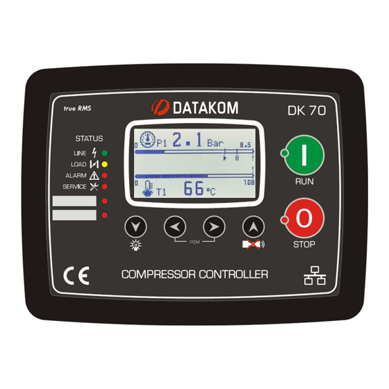
DK-70 is a next generation compressor controller
providing control of a screw or piston type air compressor
driven by electric motor.
DK-70 offers wide internet-based communication
capabilities satisfying tomorrow's needs. It allows remote
monitoring and control over internet. A mobile phone app
is also available for ease of use.
The unit incorporates all functions needed in a
compressor control panel, eliminating the need for extra
modules in the panel and lowering panel cost.
The early start function analyzes the air consumption
trend and starts the compressor before the pressure falls
below the low set limit.
Using the Weekly Schedule Program and Pressure
Calendar functions, the compressor can be programmed
to start on given hours and days of the week with user
defined set pressure values.
The unit is supplied from the utility. Fault contacts and
senders are internally supplied, eliminating the need for a
supply transformer in the panel.
The 2.9", 128x64 pixel LCD screen displays values in
bigger size with graphic support.
The controller is designed to conform to highest industrial
standards in safety, vibration, EMC and environmental
conditions.
Firmware updates can be done easily via the USB port.
The device can be monitored and programmed via USB,
RS-485, Ethernet, WIFI and GPRS using the Windows
based free PC software.
Rainbow Scada web service enables central remote
monitoring and control of an unlimited number of
compressors.
DK-70
INTERNET BASED
COMPRESSOR
CONTROLLER
FEATURES
Ethernet (optional)
GSM-2G-3G-4G-NB/IOT-SMS (optional)
Wi-Fi connection (optional)
Embedded Web server
Monitoring & programming & control
Canbus multi-compressor operation (opt.)
Modbus RS-485 (optional)
RS-232 (optional)
Modbus TCP/IP - SNMP
USB Flash Drive socket (optional)
USB GPS support
USB Device Port
FUNCTIONS
Equal aging, multiple compressor control
Weekly schedule and pressure calendar
5 independent service counters
Star / Delta starting
0-10V and 4-20mA frequency inverter control
8 programmable relay outputs
8 programmable digital inputs
3 pressure sender inputs
4 temperature sender inputs
Adjustable sender curves
Current, voltage, power, and phase sequence
protections
V & I harmonic analysis and oscilloscope
Fully closed front panel (IP65 with gasket)
CONNECTIONS
3 phase 4 wire, star
3 phase 4 wire, delta
3 phase 3 wire, 2 CTs (L1-L2)
3 phase 3 wire, 2 CTs (L1-L3)
2 phase 3 wire, L1-L2
1 phase 2 wire
Advertisement
Table of Contents

Subscribe to Our Youtube Channel
Related Manuals for Datakom DK-70


Summary of Contents for Datakom DK-70
- Page 1 DK-70 INTERNET BASED COMPRESSOR CONTROLLER DESCRIPTION FEATURES DK-70 is a next generation compressor controller Ethernet (optional) providing control of a screw or piston type air compressor GSM-2G-3G-4G-NB/IOT-SMS (optional) driven by electric motor. Wi-Fi connection (optional) Embedded Web server DK-70 offers wide internet-based communication Monitoring &...
- Page 2 DK-70 family compressors. Follow carefully the advice given in the document. These are often good practices for the installation of compressor controllers which reduce future issues. For all technical queries, please contact Datakom at the e-mail address below: technical.support@datakom.com.tr QUERIES If additional information to this manual is required, please contact the manufacturer directly at: technical.support@datakom.com.tr...
- Page 3 REVISION HISTORY REVISION DATE AUTHOR DESCRIPTION 26.03.2019 First Edition TERMINOLOGY CAUTION: Potential risk of injury or death. WARNING: Potential risk of malfunction or material damage. ATTENTION: Useful hints for the understanding of device operation. - 3 -...
- Page 4 SPARE PARTS Screw type bracket Self-retaining type bracket Stock Code=J10P01 (per unit) Stock Code=K16P01 (per unit) Sealing Gasket, Stock Code= L057P01 - 4 -...
- Page 5 SAFETY NOTICE Failure to follow the following instructions may result in death or serious injury. ▪ Electrical equipment should be installed only by a qualified specialist. No responsibility is assured by the manufacturer or any of its subsidiaries for any consequences resulting from non- compliance to these instructions.
-
Page 6: Table Of Contents
TABLE OF CONTENTS 1. INSTALLATION INSTRUCTIONS 2. MOUNTING 2.1 DIMENSIONS 2.2 SEALING GASKET 2.3 ELECTRICAL INSTALLATION 3. TERMINAL DESCRIPTIONS 3.1. POWER SUPPLY INPUT 3.2. AC VOLTAGE INPUTS 3.3. AC CURRENT INPUTS 3.4. DIGITAL INPUTS 3.5. PT100 TEMPERATURE SENDER INPUT 3.6. ANALOG TEMPERATURE SENDER INPUTS 3.7. - Page 7 10. EVENT RECORDS 11. STATISTICAL COUNTERS 12. OPERATION OF THE UNIT 12.1. SELECTION OF OPERATION MODE 12.2. STOPPING METHOD 12.3. STARTING THE COMPRESSOR 12.4. UNLOADING AND RELOADING THE COMPRESSOR 13.5. STOPPING AND RESTARTING FOLLOWING OUTPUT PRESSURE 13. ALARMS AND WARNINGS 13.1.
- Page 8 20. DATA RECORDING 20.1. DATA RECORDING MEDIA 20.2. DIRECTORY STRUCTURE 20.3. CSV FORMAT 20.4. RECORDED DATA LIST, RECORD PERIOD 21. SOFTWARE FEATURES 21.1. REMOTE START 21.2. SINGLE PHASE OPERATION 21.3. EXTERNALLY CONTROLLED DIGITAL OUTPUTS 21.4. RESETTING THE CONTROLLER 21.5. VARIABLE SERVICE TIMER SELECTION 21.6.
-
Page 9: Installation Instructions
1. INSTALLATION INSTRUCTIONS Before installation: ▪ Read the user manual carefully; determine the correct connection diagram. ▪ Remove all connectors and mounting brackets from the controller, then pass the controller through the mounting opening. ▪ Place the mounting brackets and tighten. Do not tighten too much, this can break the enclosure. ▪... -
Page 10: Mounting
2. MOUNTING 2.1. DIMENSIONS Dimensions: 211x162x42mm Panel cutout: 176x121mm minimum Weight: 500g (approx.) - 10 -... - Page 11 The unit is designed for panel mounting. The user should not be able to access parts of the unit other than the front panel. Mount the unit on a flat, vertical surface. Before mounting, remove the mounting brackets and connectors from the unit, then pass the through the mounting opening.
- Page 12 Two different types of brackets are provided: Self-retaining type bracket Screw type bracket Installation of screw type bracket Installation of self-retaining type bracket Do not tighten too much, this may break the unit. - 12 -...
-
Page 13: Sealing Gasket
2.2. SEALING GASKET Panel Gasket Module The rubber gasket provides a watertight means of mounting the module to the compressor panel. Together with the gasket, IEC 60529-IP65 protection can be reached from the front panel. A short definition of IP protection levels is given below: Digit Description of Protection Level 0 Not protected... -
Page 14: Electrical Installation
2.3. ELECTRICAL INSTALLATION Do not install the unit close to high electromagnetic noise emitting devices like contactors, high current busbars, switch-mode power supplies and the like. Although the unit is protected against electromagnetic disturbance, excessive disturbance can affect the operation, measurement precision and data communication quality. ▪... -
Page 15: Terminal Descriptions
3. TERMINAL DESCRIPTIONS 3.1. POWER SUPPLY INPUT Supply voltage: 85-300 VAC or 88-400VDC Polarity: Indifferent Maximum power: 7W @ 230VAC. (All features active, relay outputs empty) Typical operating power: 2W @ 230VAC. (All features passive, relay outputs empty) Isolation: 2000 VAC (between voltage inputs and supply inputs) 3.2. -
Page 16: Ac Current Inputs
3.3. AC CURRENT INPUTS Measurement method: True RMS Sampling rate: 8000 Hz Harmonic analysis: Up to 31 harmonic Supported topologies: 3 Phase 3 CT 3 Phase 2 CT L1-L2 2 Phase 2 CT L1-L2 1 Phase 1 CT CT secondary: 5A or 1A Measuring range: 5/5 - 5000/5A minimum... - Page 17 Connecting CTs: Be sure to connect each CT to the relevant phase input with the correct polarity. Mixing CTs between phases will cause faulty power and pf readings. Many combinations of incorrect CT connections are possible, so check both the order of the CTs and their polarities.
- Page 18 EFFECT OF POLARITY REVERSAL The compressor is still loaded with 100 kW on each phase. The load power factor (PF) is 1. PF in phase L2 will show -1.00 due to reverse polarity. The result is that total compressor power displayed by the controller is 100 kW.
-
Page 19: Digital Inputs
3.4. DIGITAL INPUTS Number of inputs: 8 inputs, all configurable Structure: Serial diode, with 113k-ohm resistor to the GND terminal Function selection: From list Contact type: Normally open or normally closed (programmable) Switching: Active under positive-DC or AC voltage, passive when left open Low level threshold: 1.0V-DC/AC High level threshold:... -
Page 20: Pressure Sender Inputs
3.7. PRESSURE SENDER INPUTS Number of inputs: 3 inputs, additional +12V (PRES+) sender supply Structure: 50-ohm resistance to ground Measurement: Analog DC current measurement Function: The measured current value is converted to pressure via the programmed sender curve. Nominal input current: 4-20mA-DC Current measurement 0-30mA-DC... -
Page 21: Ma Analog Outputs
3.9. 4-20 mA ANALOG OUTPUTS These outputs transfer the analog measurement information to external PLC systems. Any desired measurement can be fed to the PLC system. Output values can be configured for 4mA and 20mA. The outputs are isolated. This ensures that they operate safely and correctly without being affected by ground voltage differences. -
Page 22: Input/Output Expansion
3.11. INPUT/OUTPUT EXPANSION The controller offers the possibility to add 32 digital inputs and 32 digital outputs in addition to the existing inputs and outputs. The number of digital inputs can be increased using the DKG-188 Digital Input Expansion module, each unit providing 8 additional inputs. -
Page 23: Port (Optional)
3.12. RS-485 PORT (OPTIONAL) Structure: RS-485, isolated. Connection: 3 wire (A-B-GND). Half duplex Data transfer rate: 2400-115200 baud, adjustable. Data type: 8-bit data, no parity, 1 bit stop Isolation: 250VAC, 1 minute Termination: External 120-ohm termination resistance required. Common mode voltage: -0.5 VDC ... -
Page 24: Ethernet Port (Optional)
3.13. ETHERNET PORT (OPTIONAL) Description: IEEE802.3 compliant, 10/100 Base-TX RJ45 ethernet port Data transfer rate: 10/100 Mbit/s, auto detecting Connector: RJ45 Cable type: CAT5 or CAT6 Isolation: 1500 VAC, 1 minute Max distance: 30m. Function: Embedded TCP/IP, Web Server, Web Client, SMTP, e-mail, SNMP, Modbus TCP_IP STANDARD ETHERNET CABLE... -
Page 25: Usb Device Port
The RainbowPlus software can be downloaded from www.datakom.com.tr . The connector on the module is of USB-B type. Thus, A to B type USB cable should be used. This is the same cable used for USB printers. -
Page 26: Usb Host Port (Optional)
3.15. USB HOST PORT (OPTIONAL) USB HOST Port USB FLASH DRIVE USB host port is available in units with COMM option. Description: USB 2.0, non-isolated Supply output: 5V, 300mA max. Data transfer rate: Full speed 1.5/12 Mbits/s, auto detecting Connector: USB-A (PC type connector) Cable length: Max. -
Page 27: Port (Optional)
3.16. RS-232 PORT (OPTIONAL) Description: RS-232, isolated. Function: External GSM modem, external PSTN modem Connector: DB-9 (9 pin male) Connection: 5 wire (Rx-Tx-DTR-CxD-GND). Full duplex. Baud rate: 2400-115200 baud, adjustable. Data type: 8 bit data, no parity, 1 bit stop Isolation: 250VAC, 1 minute Max distance:... -
Page 28: Gsm Modem (Optional)
3.17. GSM MODEM (OPTIONAL) The optional GSM modem offers the advantage of being internally powered and is fully compatible with the unit. It does not require any special setup. The 850/1900 MHz magnetic antenna together with its 2-meter cable is supplied with the internal modem option. -
Page 29: Wifi Communication (Optional)
3.18. Wi-Fi COMMUNICATION (OPTIONAL) Wi-Fi protocols: 802.11 b/g/n Frequency range: 2.4 GHz ~ 2.5 GHz (2400M ~ 2483.5M) Network Protocols: IPv4, TCP/UDP Security: WPA/WPA2 Functionality: Web Client, E-mail, Modbus TCP_IP - 29 -... -
Page 30: Topologies
4. TOPOLOGIES Various topologies can be selected from the program parameters. 4.1. 3 PHASE, 4 WIRE, STAR 4.2. 3 PHASE, 4 WIRE, DELTA - 30 -... - Page 31 4.3. 3 PHASE, 3 WIRE, DELTA, 2 CT (L1-L2) 4.4. 3 PHASE, 3 WIRE, DELTA, 2 CT (L1-L3) - 31 -...
-
Page 32: Phase, 3 Wire, Delta, 2 Cts (L1-L2)
4.5. 2 PHASE, 3 WIRE, DELTA, 2 CTs (L1-L2) 4.6. 1 PHASE, 2 WIRE - 32 -... -
Page 33: Connection Diagram
5. CONNECTION DIAGRAM - 33 -... - Page 34 Term Function Technical data Description Connect the PHASE terminal of the AC SUP+ 85-300V-AC or supply to this terminal. If DC supply is 88-400V-DC used, connect the (+) terminal. Reverse connection does not affect device operation. No connection Connect the NEUTRAL terminal of the AC SUP- Neutral or 0 VDC supply to this terminal.
- Page 35 Term Function Technical data Description Relay COM1 Relay COM1 output, Common terminal for Relay-1-2-3-4. 5A/250V-AC This relay’s function is programmable from Relay 1 Output Normally open outputs 5A/250V-AC function list. Factory setting is Compressor MAIN Relay output. This relay’s function is programmable from Relay 2 Output function list.
- Page 36 Term Function Technical data Input MAINS NEUTRAL 0-300V-AC Neutral terminal for utility mains. Connect the utility mains phases to these MAINS L3 Phase Utility mains phase terminals. High and low limits for mains inputs, 0-300V-AC MAINS L2 Phase phase voltages can be programmed. MAINS L1 Phase - 36 -...
-
Page 37: Technical Specifications
6. TECHNICAL SPECIFICATIONS Supply input: Input voltage: 85-300V-AC or 88-400V-DC Frequency: DC to 500Hz Power consumption: 7W maximum Voltage inputs: Measurement range: 0 - 300 V-AC (Ph-N) , 0 - 520V Ph-Ph Frequency range: 0-500 Hz. Burden: < 0.1VA per phase VT Range: 0.1/1 –... - Page 38 IP Protection Rating: IP54 front panel, IP30 back panel. Dimensions: 211x162x42mm (WxHxD) Panel Cutout Dimensions: 176x121mm minimum Weight: 500g (approx.) Enclosure: High temperature, non-flammable, ROHS compliant ABS/PC Mounting: Front panel mounted with rear retaining plastic brackets. EU Directives Conformity -2014/35/EC (Low voltage) -2014/30/EC (electromagnetic compatibility) Norms of reference: EN 61010 (safety requirements)
-
Page 39: Description Of Controls
7. DESCRIPTION OF CONTROLS 7.1. FRONT PANEL FUNCTIONALITY LCD screen LINE (MAIN relay) RUN mode status indicator işareti button LOAD (Load relay) status indicator Fault status STOP mode indicators button Programmable LED indicators Previous Next screen in screen in the same group. same group. -
Page 40: Pushbutton Functions
7.2. PUSHBUTTON FUNCTIONS BUTTON FUNCTION Select RUN mode. Compressor starts running. Select STOP mode. Compressor stops. The controller resets if held pressed for 30 seconds. Navigates to next display screen in the same group. LAMP TEST (long press). Navigate to previous display screen group. Navigate to next display screen group. -
Page 41: Display Screen Organization
7.3. DISPLAY SCREEN ORGANIZATION The unit measures a large number of electrical and compressor parameters. The display of the parameters is organized as PARAMETER GROUPS and items in a group. Navigation between different groups is made with buttons. Each depression of the button will cause the display to switch to the next group of parameters. -
Page 42: Measured Parameters
7.4. MEASURED PARAMETERS The unit performs a detailed set of AC measurements. The list of measured Electrical Parameters is below: Mains voltage phase L1-Neutral Mains kW phase L2 Mains voltage phase L2-Neutral Mains kW phase L3 Mains voltage phase L3-Neutral Mains total kW Mains phase neutral voltage average value Mains kVA phase L1... -
Page 43: Led Lamps
7.5. LED LAMPS LINE RUN mode (MAIN relay) indicator status indicator LOAD (Load relay) status indicator Alarm indicator Service request indicator Programmable LED indicators STOP mode indicator STATUS LEDS: LINE (MAIN RELAY): If RUN mode is selected and there are no conditions to prevent the compressor from starting, the main relay engages and this LED turns on. -
Page 44: Waveform Display & Harmonic Analysis
8. WAVEFORM DISPLAY & HARMONIC ANALYSIS The unit features a waveform display along with a precision harmonic analyzer for mains voltages and currents. Both phase to neutral and phase to phase voltages are analyzed, thus there are 9 channels in total. - Page 45 The harmonic analyzer uses the Fast Fourier Transform (FFT) algorithm which runs twice a second on the selected channel. The sample memory is of 1024 samples length and 13 bits resolution with a sampling rate of 4096Hz. According to theory, a periodic signal may have only odd multiples of the main frequency. Thus, in a 50Hz network, harmonics will be found only at 150, 250, 350, 450Hz etc...
-
Page 46: Minimum, Maximum & Demand Values
9. MINIMUM, MAXIMUM & DEMAND VALUES Demand values are the calculated average values of measured parameters over a user defined period. Average values are compared to the demand values at the end of the period, and if the new value is greater, it is recorded as the demand value. -
Page 47: Event Records
10. EVENT RECORDS The unit features more than 400 event logs with date-time stamp and full snapshot of measured values at the moment that the event has occurred. Stored values in an event record are listed below: -event number -event type / fault definition (see below for various event sources) -date and time -operation mode &... - Page 48 When displaying event logs: will display the next information in the same event. will display the previous information in the same event. will display the same information of the previous event. will display the same information of the next event. - 48 -...
-
Page 49: Statistical Counters
11. STATISTICAL COUNTERS The unit provides a set of incremental counters for statistical purposes. The counters are listed below: -total mains kWh -total mains kVArh inductive -total mains kVArh capacitive -total running hours -loaded running hours -Number of motor starts -Number of fan starts -Minutes left until next oil service request digital input pulse counter... -
Page 50: Operation Of The Unit
12. OPERATION OF THE UNIT 12.1. SELECTION OF OPERATION MODE When power is supplied, the unit enters STOP mode and the STOP LED turns on. The compressor is started with the REMOTE START signal or by pressing the RUN button. If Safety Timer has not expired yet, the RUN LED blinks until the timer expires. -
Page 51: Starting The Compressor
12.3. STARTING THE COMPRESSOR Pressing the RUN button or issuing a Remote START/STOP command if enabled will switch the compressor to run mode. In this phase, the controller decides to start the compressor if the output pressure (Main Pressure measurement value) drops below Start Pressure (or when the pressure switch closes). -
Page 52: Alarms And Warnings
13. ALARMS AND WARNINGS If any of the measured parameters of the controller goes outside the preset limits, a fault condition occurs. When a fault occurs, the alarm pop-up screen is displayed and the alarm function is activated. In order to transfer the alarm condition to other systems, the alarm function can be assigned to a relay output. - Page 53 13.1. SERVICE REQUEST ALARM The service LED is designed to help the periodic maintenance of the compressor consistently. The periodic maintenance is basically carried out after a given engine hours (for example 2000 hours). The unit features 5 independent service counters. When any of the counters expires, the service LED turns If the Stop Service Request parameter is set to 1, the compressor behaves according to the table below: TIME TO SERVICE ACTION TAKEN...
-
Page 54: Alarms
13.2. ALARMS ALARM DESCRIPTION HIGH / LOW VOLTAGE If the phase voltages are outside the programmed limits for the duration of the relevant Alarm Timer, this alarm occurs. The alarms are: High Voltage Alarm, Low Voltage Alarm HIGH / LOW If the frequency is outside the programmed limits, this alarm occurs. - Page 55 ALARM DESCRIPTION If the temperature values are outside the programmed limits for the duration of the relevant Alarm Timer, this alarm occurs. Each temperature sender has its independent alarm. The alarms are: HIGH / LOW High Temperature Sender-1, High Temperature Sender-2, High TEMPERATURE Temperature Sender-3, High Temperature Sender-4, PT100 High Temperature, Low Temperature Sender-1, Low Temperature Sender-2,...
- Page 56 ALARM DESCRIPTION If the compressor is running loaded, and the Main Pressure measurement is above the Start Pressure parameter, pressure difference alarms are checked. Otherwise the Pressure Difference Alarm conditions are not checked. PRESSURE DIFFERENCE Pressure difference alarms are listed below: ALARMS Sender-2 Pressure Difference Alarm: If P12 (P1-P2) pressure difference exceeds the P1-P2 Pressure Difference Alarm parameter, Sender-2...
-
Page 57: Warnings
13.3. WARNINGS WARNING DESCRIPTION HIGH TEMPERATURE If the temperature values exceed the configured warning limits, this warning is issued. Each temperature sender has its independent warning. The warnings are: High Temperature-1, High Temperature-2, High Temperature-3, High Temperature-4 . WAIT 1 HOUR TO STOP If the motor has started (perform start-stop cycles) Max. - Page 58 If the Take Load Command Source parameter is set to “1 : Digital Input” and DIGITAL INPUT TAKE one of the digital input functions is configured as “Take Load Command”, this LOAD COMMAND warning is issued when the digital input sends the “take load” command and the compressor takes the load.
-
Page 59: Programming
14. PROGRAMMING 14.1. RESETTING TO FACTORY DEFAULTS To perform a factory reset: -Press and hold the STOP, LAMP TEST and ALARM MUTE buttons for 5 seconds, -The screen will display “FACTORY RESET”, -Press the RIGHT ARROW key and hold for 5 seconds, -Factory parameters will be reprogrammed to memory. -
Page 60: Navigating Between Menus
14.3. NAVIGATING BETWEEN MENUS The programming mode is organized into a 2-level menu system. Main menu consists of program groups. Program parameters are located inside the groups. Upon entering programming mode, the list of program groups will be displayed. Moving between groups buttons. -
Page 61: Modifying Parameter Value
14.4. MODIFYING PARAMETER VALUE Previous parameter Long press: Return to top Next menu parameter Decrement Increment parameter parameter value value 14.5. EXITING PROGRAMMING MODE Press and hold the button for 5 seconds to exit programming mode. If no operation is performed, the controller will exit programming mode automatically after 2 minutes. Long press: Exit programming... -
Page 62: Program Parameter List
1: Pressure Calendar enabled 0: no modem / no GPS 1: Internal modem / no GPS 2: External Datakom modem / no GPS Modem / GPS Selection 3: External generic modem / no GPS 4: No modem / RS-232 GPS... - Page 63 15.1. CONTROLLER CONFIGURATION GROUP (cont.) Parameter Definition Unit Factory Description Setting Port number of the internal Web server. Web Server Port 65535 The unit responds to incoming queries to this port only. Port number of the Internal Modbus Modbus over TCP/IP TCP/IP server.
- Page 64 15.1. CONTROLLER CONFIGURATION GROUP (cont.) Parameter Definition Unit Factory Description Setting 0: SMS commands not accepted SMS Commands 1: SMS commands accepted only from Enabled listed telephone numbers. 0: No periodic (hourly) event records. Periodic Event Recording 1: Periodic (hourly) event records Enabled enabled.
-
Page 65: Electrical Parameters Group
15.2. ELECTRICAL PARAMETERS GROUP Parameter Definition Unit Factory Description Setting Current Transformer Current transformer primary current value 10000 Primary Voltage Transformer Ratio. The voltage Voltage Transformer and power measurements are multiplied by 5000.0 Ratio this ratio. If a transformer is not used, this value must be set to 1.0. - Page 66 15.2. ELECTRICAL PARAMETERS GROUP (cont.) Parameter Definition Unit Factory Description Setting If the reactive power of any channel is Reactive Inductive Alarm inductive and above this limit, an alarm kVAr 9999 Value occurs. If this value is set to 0, the alarm is disabled.
- Page 67 15.2. ELECTRICAL PARAMETERS GROUP (cont.) Parameter Unit Min Max Factory Description Definition Setting Voltage Unbalance 0: non-latching Alarm Latching 1: latching If the current unbalance exceeds this limit, an alarm Current Unbalance occurs. If this value is set to 0, the alarm is Alarm disabled.
- Page 68 15.2. ELECTRICAL PARAMETERS GROUP (cont.) Parameter Definition Unit Factory Description Setting This parameter selects the sender to be used to control the heating relay. 0: Temperature Sender-1 (T1) Temperature Sender for 1: Temperature Sender-2 (T2) Heating Relay 2: Temperature Sender-3 (T3) 3: Temperature Sender-4 (T4) 4: PT100 Temperature Sender (T5) °C...
- Page 69 15.2. ELECTRICAL PARAMETERS GROUP (cont.) Parameter Definition Unit Factory Description Setting 3200.0 If the 0-10V Analog output is used for 0-10V Analog Output sending a voltage value proportional to MIN Value a measurement value (NOT motor or fan drive), MIN value must be set to the measurement value corresponding to 0-10V Analog Output 3200.0...
-
Page 70: Compressor Parameters Group
15.3. COMPRESSOR PARAMETERS GROUP Parameter Definition Unit Max Factory Description Setting 0: Disabled Pressure Sender-1 1: Pressure Switch Control Setting 2: Pressure Sender Pressure Sender-1 High The upper measurement limit for the 1 99.9 16.0 Limit pressure sender must be entered here. High Pressure-1 Alarm If the 1 pressure measurement value... - Page 71 15.3. COMPRESSOR PARAMETERS GROUP (cont.) Parameter Definition Unit Factory Description Setting 0: Disabled 1: Absolute Temperature Temperature Sender-2 2: Temperature Difference °C Configuration 3: Motor PTC (If sender reading exceeds 2000 Ohms, MPTC High Temperature alarm occurs.) The upper measurement limit of the 2 Temperature Sender-2 °C -400...
- Page 72 15.3. COMPRESSOR PARAMETERS GROUP (cont.) Parameter Definition Unit Factory Description Setting Service A is synchronized to this value Service A Hours (Timer) Hours 32767 2000 when reset. If this parameter is set to 0, service A warning is disabled. Service A is synchronized to this value Service B Hours (Timer) Hours 32767...
- Page 73 15.3. COMPRESSOR PARAMETERS GROUP (cont.) Parameter Definition Unit Factory Description Settings 0: Disabled Pressure Sender-2 1: Pressure Switch Control Setting 2: Pressure Sender Pressure Sender-2 High The upper measurement limit of the 2 99.9 16.0 Limit pressure sender must be entered here. High Pressure-2 Alarm If the 2 pressure measurement...
- Page 74 15.3. COMPRESSOR PARAMETERS GROUP (cont.) Parameter Definition Unit Factory Description Settings The upper measurement limit of the 3 Temperature Sender-3 °C -400 temperature sender must be entered High Limit here. If the 3 temperature measurement High Temperature-3 °C -400 value exceeds this parameter, an alarm Alarm Value occurs.
- Page 75 15.3. COMPRESSOR PARAMETERS GROUP (cont.) Parameter Unit Factory Description Definition Settings 0: Disabled Pressure Sender-3 1: Pressure Switch Control Setting 2: Pressure Sender Pressure Sender-3 The upper measurement limit of the 3 99.9 16.0 High Limit pressure sender must be entered here. High Pressure-3 If the 3 pressure measurement value...
- Page 76 15.3. COMPRESSOR PARAMETERS GROUP (cont.) Parameter Unit Factory Description Definition Setting Fan PID Derivative 99.9 Fan PID control D coefficient. (D) coefficient Fan PID Correction 99.9 Fan PID control inverse I coefficient. (%) coefficient 99.9 Refer to section 25.9 for detailed Fan PID Delay Timer information.
- Page 77 15.3. COMPRESSOR PARAMETERS GROUP (cont.) Parameter Definition Unit Factory Description Setting 0: No effect 1: The oiling counter is set equal to Oiling Reset Oiling Counter Period parameter. This parameter is not saved to memory, it is always read as 0. Pressure and 0: Non-latching Temperature Alarms...
- Page 78 15.3. COMPRESSOR PARAMETERS GROUP (cont.) Parameter Definition Unit Factory Description Setting This parameter selects the main temperature sender to control the compressor. Main Temperature 0: Temperature Sender-1 (T1) Sender 1: Temperature Sender-2 (T2) 2: Temperature Sender-3 (T3) 3: Temperature Sender-4 (T4) 4: PT100 Temperature Sender (T5) This parameter selects the main pressure sender to control the compressor.
-
Page 79: Adjust Date And Time
15.4. ADJUST DATE AND TIME Date-time information is received from the built-in, battery-powered real time clock. Parameter Definition Unit Description Day of the month Month Month information Year Last two digits of the year Hour Hour of the day Minute Minute of the hour Second Second of the minute... -
Page 80: Pressure Calendar
15.6. PRESSURE CALENDAR The controller offers 32 independent pressure calendars. For each pressure calendar; the starting day, hour and minute, the duration, Start Pressure, and Stop Pressure can be independently configured. Start Pressure and Stop Pressure cannot be set higher than 0.2 Bar above Main Pressure High Alarm Limit. This allows for the compressor to run in the desired day and hour of the week for the desired amount of time with the desired Start Pressure and Stop Pressure. - Page 81 15.7. SENSOR CHARACTERISTICS The controller offers 3x 4-20mA pressure sender inputs, 4x analog temperature sender inputs and 1x PT100 temperature sender inputs. Each sender has a 16-step programmable curve. The curve parameters of only one of the analog temperature senders is explained below. All of the other analog temperature senders have the same parameters.
- Page 82 The curve parameters of only one of the 4-20mA pressure senders is explained below. All of the other pressure senders have the same parameters. Each pressure sender has the following programmable parameters: Parameter Definition Unit Factory Description Settings Sender Curve-1 mA 512.0 Step-1 mA value Sender Curve-1 pressure...
- Page 83 The PT100 temperature sender’s curve parameters are explained below. PT100 sender has the following programmable parameters: Parameter Definition Unit Factory Description Setting Sender Curve-1 ohm 6553.5 60.2 Step-1 ohm value °C Sender Curve-1 temp -32768 32767 -100 Step-1 temperature value Sender Curve-2 ohm 6553.5 80.3...
-
Page 84: Input Configuration
15.8. INPUT CONFIGURATION The controller offers 8 digital inputs. The number of these inputs can be increased to 40 using external extension input modules. The parameters of only one of the digital inputs are explained below. All of the other digital inputs have the same programmable parameters. -
Page 85: Digital Output (Relay) Configuration
15.9. DIGITAL OUTPUT (RELAY) CONFIGURATION The following parameters determine the functions of the programmable digital outputs (relays) and LEDs. The controller offers 8 programmable digital outputs (relays) and 2 programmable LEDs. The number of relay outputs on the device can be increased up to 40 using the External Relay Module. Parameter Definition Factory Terminal... - Page 86 OUTPUT FUNCTION LIST Description High Temp. Snd-1 Description Description Low Temp. Snd-1 Horn Button 4 (Right MENU High Temp. Snd-2 Flashing relay button) simulation Low Temp. Snd-2 Phase order fault Button 5 (RUN button) Temp. Diff. Alarm Snd-2 alarm simulation High Temp.
-
Page 87: Engine Serial Number
15.10. ENGINE SITE ID Engine site ID is used to identify the compressor on which the controller is mounted. In order to be able to distinguish compressor in the SMS and e-mail messages sent by the controller and also on the webpage, the engine site ID is written in the title. One line of up to 20 characters can be set as the engine site ID. -
Page 88: Gsm Modem Parameters
15.13. GSM MODEM PARAMETERS Parameter Definition Description APN username may be required depending on the GSM operator. For APN Username accurate APN username information, refer to your GSM operator. If APN username is required, an APN password might also be required APN Password depending on the GSM network provider. -
Page 89: Ethernet Parameters
Rainbow Address-1 wss1.datakom.com.tr here. The unit sends a data packet to the defined Rainbow Address-2 address at each refresh period. The DATAKOM server address is set as the first server address. - 89 -... - Page 90 15.14. ETHERNET PARAMETERS (cont.) Parameter Definition Factory Setting Description This is the account name appearing in the “from” tab E-mail Account Name d500_a of the e-mail recipient. E-mail Account d500_1234 This is the password of the above e-mail account. Password This is the outgoing mail server address of the above E-mail Server Name smtp.mail.yahoo.com...
-
Page 91: Sntp Parameter
15.15. SNTP PARAMETERS SNTP (simple network time protocol) communication allows the controller to query high precision, atomic clock-based date/time servers through the Internet and to synchronize its internal real time clock to these servers. This feature allows the internal RTC to reach atomic clock precision. Parameter Definition Factory Setting Description... -
Page 92: Ethernet Configuration
16. ETHERNET CONFIGURATION Related parameters are: Parameter Definition Factory Set Description This is the IPv4 (internet protocol version 4) address that the unit will require from the DHCP (dynamic host control protocol) server. Network IP Address 0.0.0.0 If this parameter is set to 0.0.0.0 then the unit will require any IPv4 address from the DHCP server. -
Page 93: Gsm Configuration
17. GSM CONFIGURATION Related parameters are: Parameter Definition Factory Set Description 0: SMS messages disabled SMS Enable 1: SMS messages enabled GPRS Connection 0: GPRS disabled Enable 1: GPRS enabled This parameter controls SMS sending when mains SMS on Mains voltages status is changed. -
Page 94: Wi-Fi Configuration
18. Wi-Fi CONFIGURATION Related parameters are: Parameter Definition Factory Set Description This is the name of wireless network that you want to ………...…. SSID connect. This is the password of wireless network that you want ………...…. Wi-Fi Password to connect. This is the IPv4 (internet protocol version 4) address that the unit will require from the DHCP (dynamic host control protocol) server. -
Page 95: Sms Commands
19. SMS COMMANDS SMS messages are only accepted from phone numbers set in SMS1-2-3-4 PHONE NUMBERS parameters. Responses to SMS messages are sent to all recorded numbers. SMS messages must be sent exactly as below, without spaces. Only CAPITAL LETTERS must be used. COMMAND DESCRIPTION RESPONSE... -
Page 96: Data Recording
20. DATA RECORDING 20.1. DATA RECORDING MEDIA Data can be recorded in USB flash memory or MICRO-SD memory card. Both options are available. As soon as a USB flash memory or a MICRO-SD card is inserted, the unit will start data recording and continue until the memory is removed. -
Page 97: Directory Structure
20.2. DIRECTORY STRUCTURE The unit records data to a USB-Flash memory or micro-SD flash memory card. Last day of SITE-ID Year 2012 the year Year 2011 First day of Previous years the year The unit will record data in a directory with the first 11 characters of its site-id parameter. In order to avoid confusion between records, it is highly recommended to configure the site-id parameter according to the compressor installation site. -
Page 98: Recorded Data List, Record Period
20.4. RECORDED DATA LIST, RECORD PERIOD The recording period is adjustable between 5 seconds and 3600 seconds (1 hour) from the Data Logging Period parameter. Short recording periods will provide better resolution while using more data in the memory. One data record is typically 250 bytes long. If recorded with a 5 second interval, it will consume 4.32 MB per day (250x12x60x24). -
Page 99: Software Features
21. SOFTWARE FEATURES 21.1. REMOTE START The unit can be programmed to enter RUN mode when a Remote Start signal is received, and to enter STOP mode when the signal is not received. Any digital input can be programmed as Remote Start/Stop signal. This operation can be performed from the Input Configuration program menu. -
Page 100: Variable Service Timer Selection
21.5. VARIABLE SERVICE TIMER SELECTION The controller offers the option of calculating service hours with a coefficient which is a function of the main temperature measurement value. Variable coefficient use can be selected via the Variable Service Hours parameter. If this parameter is disabled, all service counters are calculated with a 1.00 multiplier independent of the main temperature measurement. -
Page 101: Preventing Pressure Loss
21.6. PREVENTING PRESSURE LOSS If the main pressure measurement remains higher than Start Pressure for a longer duration than Off- load Working Timer, the controller stops the motor. If the main pressure measurement drops below Start Pressure while the motor is stopped, the motor is restarted. Until the compressor takes the load again, the amount of time elapsed will be Star Timer + Star ->... -
Page 102: Pid Control And Analog Output (Pwm)
21.7. VARIABLE UNLOAD TIMER This feature is designed to conserve energy by preventing the motor from running off-load for extended periods of time in low air consumption scenarios. When the Main Pressure measurement reaches the set value, the LOAD relay opens first, the motor keeps running off-load for the duration of Safety Timer or Unload Timer (whichever is longer), then stops. -
Page 103: Motor Ptc Input
21.10. MOTOR PTC INPUT The unit allows for a motor PTC (thermal sensor) connection to the 2 , or 4 temperature sender input. If the motor PTC sensor is connected to one of these inputs, the relevant sender input’s Temperature Sender Configuration must be set to “Motor PTC”. -
Page 104: Modbus Communication
22. MODBUS COMMUNICATION The unit offers MODBUS in the following forms: -RS485 serial port, adjustable data transfer rate between 2400 and 115200 baud -MODBUS-TCP/IP over the Ethernet port (10/100Mb) -MODBUS-TCP/IP over GPRS Network (85/42kb), valid only with Rainbow Scada. MODBUS features of the unit: -Data transfer mode: RTU -Serial data: adjustable baud rate, 8 bit data, no parity, 1 bit stop -Modbus-TCP/IP: Ethernet 10/100Mb or GPRS Class 10. -
Page 105: Parameters For Rs-485 Modbus Operation
22.1. PARAMETERS FOR RS-485 MODBUS OPERATION Modbus Address: May be set as any value between 1 and 254. RS-485 Baud Rate: May be any value between 2400 and 115200 bauds. All devices in communication with one another must have the same baud rate. Increasing the baud rate in devices provide faster communication at the expense of communication range. - Page 106 Below is the list of available Modbus registers. ADDRESS R / W DATA COEFF. DESCRIPTION (decimal) SIZE 10240 32bit Phase L1 voltage 10242 32bit Phase L2 voltage 10244 32bit Phase L3 voltage 10246 32bit Phase L1-L2 voltage 10248 32bit Phase L2-L3 voltage 10250 32bit Phase L3-L1 voltage...
- Page 107 ADDRESS R / W DATA COEFF. DESCRIPTION (decimal) 10432 16bit Motor Status 0: Motor in Stop mode 1: Star relay closed 2: Motor running off-load before loading 3: Motor running on-load 4: Motor running off-load after loading 5: Motor stopping 10433- 64bit Alarm status bits.
- Page 108 ADDRESS R / W DATA COEFF. DESCRIPTION (decimal) 10549 32bit GPS Location Latitude 10551 32bit GPS Location Longitude 10553 32bit GPS Location Altitude 10555 32bit GPRS-GSM IP address 10557- 16bit Status bits for extension outputs 10559 10560 32bit Status bits for extension inputs 10562 16bit Reserved...
- Page 109 ADDRESS R / W DATA COEFF. DESCRIPTION (decimal) 10653 32bit Phase L1 minimum current 10655 32bit Phase L2 minimum current 10657 32bit Phase L3 minimum current 10659 32bit Minimum average current 10661 32bit x100 Minimum Frequency 10663 32bit Minimum active power 10665 32bit Reserved...
- Page 110 DIGITAL INPUT STATUS BITS DESCRIPTION DESCRIPTION Digital input-1 status Digital input-17 status (Extension input-9) Digital input-2 status Digital input-18 status (Extension input-10) Digital input-3 status Digital input-19 status (Extension input-11) Digital input-4 status Digital input-20 status (Extension input-12) Digital input-5 status Digital input-21 status (Extension input-13) Digital input-6 status Digital input-22 status (Extension input-14)
- Page 111 ALARM STATUS BITS DESCRIPTION DESCRIPTION High Voltage Alarm Sender-3 Temperature Difference Alarm Low Voltage Alarm Temperature Sender-4 Fault Alarm High Frequency Alarm High Temperature Sender-4 Alarm Low Frequency Alarm Low Temperature Sender-4 Alarm High Active Power (kW) Alarm Sender-4 Temperature Difference Alarm Low Active Power (kW) Alarm Pressure Sender-1 Fault Capacitive Power (kVAr) Alarm...
- Page 112 RELAY (DIGITAL OUTPUT) FUNCTION STATUS BITS DESCRIPTION DESCRIPTION DESCRIPTION Horn STOP Button Press High Temperature Sender-3 Flashing relay Low Temperature Sender-3 Temperature Difference Phase order fault alarm Alarm Sender-3 Voltage fault Input 1 simulation High Temperature Sender-4 Input 2 simulation Voltage OK Low Temperature Sender-4 Input 3 simulation...
- Page 113 DIGITAL INPUT ALARM BITS DESCRIPTION DESCRIPTION Digital input-1 alarm Digital input-5 alarm Digital input-2 alarm Digital input-6 alarm Digital input-3 alarm Digital input-7 alarm Digital input-4 alarm Digital input-8 alarm - 113 -...
-
Page 114: Commands
22.4. COMMANDS ADDRESS R / W DATA COEFF. DESCRIPTION (decimal) 8192 16bit Password (In order to change calibration coefficients over Modbus, the calibration password must be entered here.) 8193 16bit Button simulation. If the following hexadecimal values are entered to this address, the unit responds as if the corresponding buttons were pressed. - Page 115 ADDRESS R / W DATA COEFF. DESCRIPTION (decimal) 8197 16bit Reset service counters. If the following decimal values are entered into this address, the corresponding service counter is reset. 1: Reset all service counters. 2: Reset Service A counter. 4: Reset Service B counter. 8: Reset Service C counter.
- Page 116 ADDRESS R / W DATA COEFF. DESCRIPTION (decimal) 8223 16bit The value entered into this address is subtracted from Service C hours. 8224 16bit The value entered into this address is added to Service D hours. 8225 16bit The value entered into this address is subtracted from Service D hours.
-
Page 117: Event Records Memory Structure
22.5. EVENT RECORDS MEMORY STRUCTURE ADDRESS R / W DATA COEFF. DESCRIPTION (decimal) 32bit 32-bit date time information Bits 0-4: second/2 (0-29) Bits 5-10: minute (0-59) Bits 11-15: hour (0-23) Bits 16-20: day (1-31) Bits 21-24: month (1-12) Bits 25-31: year-2000 (0-127=2000-2127) 16bit Recording type... -
Page 118: Real Time Clock
22.6. REAL TIME CLOCK ADDRESS R / W DATA COEFF. DESCRIPTION (decimal) 5120 16bit Year (0-4096) 5121 16bit Month (1-12) 5122 16bit Day (1-31) 5124 16bit Hour (0-23) 5125 16bit Minute (0-59) 5126 16bit Second (0-59) - 118 -... -
Page 119: Snmp Communication
Min. Mains Voltages (L1, L2, L3, L12, L23, L31) Remote Controllable Digital outputs Minimum Mains Currents (I1, I2, I3, Average) Alarms Minimum Frequency Input Alarms Minimum Active power Minimum Inductive Power Warnings Minimum Capacitive Power Please contact Datakom technical support for SNMP MIB file requests. - 119 -... -
Page 120: Parameters For Ethernet Snmp
23.1. PARAMETERS FOR ETHERNET SNMP Modbus Slave Address: Can be set between 1 and 240. If only one device is present in an IP address, it is advised to leave this parameter at 1, its default value. Ethernet Enabled: This parameter must be set to 1 to enable the Ethernet port. Modbus TCP/IP Port: This parameter is typically set to 502. -
Page 121: Declaration Of Conformity
24. DECLARATION OF CONFORMITY The unit conforms to the EU directives: -2014/35/EC (Low Voltage) -2014/30/EC (electro-magnetic compatibility) Norms of Reference: EN 61010 (safety requirements) EN 61326 (EMC requirements) The CE mark indicates that this product complies with the European requirements for safety, health, environmental and customer protection.
Need help?
Do you have a question about the DK-70 and is the answer not in the manual?
Questions and answers