Table of Contents
Advertisement
Quick Links
DKG-379 User Manual Rev_02
DESCRIPTION
The DKG-379 is an advanced DC genset controller for both
variable and fixed speed systems. It is presented in 3 different
versions, as ANALOG DRIVE, POWER DRIVE and CANBUS
DRIVE.
The controller has a precision PID loop providing exact
matching of the optimal charging characteristics, as well as
overvoltage, overcurrent, overspeed, overheat protections.
The POWER DRIVE version provides a 7 Amp-DC output,
interfacing directly to the engine actuator or alternator
excitation winding without the need for a governor controller or
AVR. The CANBUS DRIVE version connects to ECU driven
electronic engines providing engine control, protection and
instrumentation without extra senders. ECU alarms are
displayed in text. All versions offer a 0-10V analog output for
speed or voltage control.
The fixed speed operation stops the genset precisely when
batteries are fully charged, providing fuel economy and
maintenance cost reductions.
The unit has precision, fully isolated measuring inputs for the
battery bank voltage and the charge current. It supports both
"positive to ground" and "negative to ground" installations.
The current is measured through a DC current shunt placed in
positive or negative output of the genset.
The genset starting is based on the precisely measured DC
battery bank voltage. Once started, the controller will perform
an optimal battery charging cycle and will stop the genset
when batteries are fully charged. The optimal charge algorithm
allows maximum battery life and minimal engine run time and
fuel consumption.
During the charge cycle, the unit controls the engine rpm (or
excitation) in order to apply the exact required DC voltage and
current to batteries. The rpm control over CANBUS-J1939 is
available for electronic engines.
The unit offers a PT100 type, battery temperature sensor
input. If used, the temperature protection will allow longer
battery life in hot environment and faster charge in cold
conditions.
DKG-379
VARIABLE SPEED DC
GENSET CONTROLLER
CANBUS AND MPU VERSIONS
Compatible with 12V, 24V and 48V DC systems
DC power drive output (7A-DC)
ECU connection through J1939 CAN option
0-10V analog control output
Isolated Volt - Amp measurements
Battery temperature input for PT100 sensor
Optimal charging, provides longer battery life
Temperature dependent battery charging
Thermal protection, short circuit protection
Dual genset mutual standby operation
100 event logs with time stamp and
measurements
Battery backed-up real time clock
Built in daily / weekly / monthly exerciser
Field adjustable parameters
RS-232 serial port
Free MS-Windows Remote monitoring SW
GSM and PSTN modem support
GSM SMS message sending on fault
MODBUS communications
Multiple language support
Customer logo display capability
MEASUREMENTS
Battery Volts
Battery temperature
Generator Volts
Generator Amps
Generator kW
Engine rpm
Engine battery Voltage
Engine Coolant Temperature
Engine Oil Pressure
Engine fuel Level
Engine Oil Temperature
V-15
(24-12-2012)
FEATURES
Advertisement
Table of Contents

Related Manuals for Datakom DKG-379


Summary of Contents for Datakom DKG-379
- Page 1 CANBUS AND MPU VERSIONS DESCRIPTION FEATURES The DKG-379 is an advanced DC genset controller for both Compatible with 12V, 24V and 48V DC systems variable and fixed speed systems. It is presented in 3 different DC power drive output (7A-DC)
- Page 2 DKG-379 unit. Follow carefully advices given in the document. These are often good practices for the installation of genset control units which reduce future issues. For all technical queries please contact Datakom at below e-mail address: datakom@datakom.com.tr RELATED DOCUMENTS FILENAME...
- Page 3 DKG-379 User Manual Rev_02 V-15 (24-12-2012) ORDERING CODES The D-500 family units are available in various options and peripheral features. Please use below information for ordering the correct version: DKG-379 -MPU -G -T Variant 00: standard unit 01...99: customer Family Code...
- Page 4 DKG-379 User Manual Rev_02 V-15 (24-12-2012) SAFETY NOTICE Failure to follow below instructions will result in death or serious injury ▪ Electrical equipment should be installed only by qualified specialist. No responsibility is assured by the manufacturer or any of its subsidiaries for any consequences resulting from the non- compliance to these instructions.
-
Page 5: Table Of Contents
DKG-379 User Manual Rev_02 V-15 (24-12-2012) TABLE OF CONTENTS INSTALLATION INSTRUCTIONS MOUNTING 2.1. DIMENSIONS 2.2. SEALING, GASKET 2.3. ELECTRICAL INSTALLATION 3. TERMINAL DESCRIPTIONS 3.1. BATTERY VOLTAGE INPUT 3.2. BATTERY BANK DC VOLTAGE INPUTS 3.3. BATTERY BANK CHARGE CURRENT INPUT 3.4. DIGITAL INPUTS 3.5. - Page 6 DKG-379 User Manual Rev_02 V-15 (24-12-2012) TABLE OF CONTENTS (continued) 13. PROTECTIONS AND ALARMS 13.1. SHUTDOWN ALARMS 13.2. LOADDUMP ALARMS 13.3. WARNINGS 14. PROGRAMMING 14.1. RESETTING TO FACTORY DEFAULTS 14.2. ENTERING THE PROGRAMMING MODE 14.3. NAVIGATING BETWEEN MENUS 14.4. MODIFYING PARAMETER VALUE 14.5.
-
Page 7: Installation Instructions
DKG-379 User Manual Rev_02 V-15 (24-12-2012) 1. INSTALLATION INSTRUCTIONS Before installation: • Read the user manual carefully, determine the correct connection diagram. • Remove all connectors and mounting brackets from the unit, then pass the unit through the mounting opening. -
Page 8: Mounting
DKG-379 User Manual Rev_02 V-15 (24-12-2012) 2. MOUNTING 2.1. DIMENSIONS Dimensions: 172x134x76mm (6.8”x5.3”x3.0”) Panel Cutout: 151x111mm minimum (6.0”x4.4”) Weight: 450g (1 lb) K43D01-EN - 8 -... - Page 9 DKG-379 User Manual Rev_02 V-15 (24-12-2012) The unit is designed for panel mounting. The user should not be able to access parts of the unit other than the front panel. Mount the unit on a flat, vertical surface. Before mounting, remove the mounting brackets and connectors from the unit, then pass the unit through the mounting opening.
- Page 10 DKG-379 User Manual Rev_02 V-15 (24-12-2012) Two different types of brackets are provided: Self retaining type bracket Screw type bracket Installation of screw type bracket Installation of self retaining type bracket Do not tighten too much, this may break the unit.
-
Page 11: Sealing, Gasket
DKG-379 User Manual Rev_02 V-15 (24-12-2012) 2.2. SEALING, GASKET Panel Gasket Module The rubber gasket provides a watertight means of mounting the module to the genset panel. Together with the gasket, 60529-IP65 protection can be reached from the front panel. A short definition of IP protection levels is given below. -
Page 12: Electrical Installation
DKG-379 User Manual Rev_02 V-15 (24-12-2012) 2.3. ELECTRICAL INSTALLATION Do not install the unit close to high electromagnetic noise emitting devices like contactors, high current busbars, switchmode power supplies and the like. Although the unit is protected against electromagnetic disturbance, excessive disturbance can affect the operation, measurement precision and data communication quality. -
Page 13: Terminal Descriptions
DKG-379 User Manual Rev_02 V-15 (24-12-2012) 3. TERMINAL DESCRIPTIONS 3.1. BATTERY VOLTAGE INPUT Supply voltage: 9 to 33VDC Cranking dropouts: Survives 0VDC during 100ms. The voltage before surge should be 9VDC minimum Overvoltage protection: Withstands 150VDC continuously. Reverse voltage: -33VDC continuous Maximum operating 250mA @ 12/24VDC. -
Page 14: Battery Bank Dc Voltage Inputs
DKG-379 User Manual Rev_02 V-15 (24-12-2012) 3.2. BATTERY BANK DC VOLTAGE INPUTS Measurement method: Isolated DC voltage measurement Sampling rate: 100K s/s Input voltage range: 0 to 70 VDC Measurement range: 0 to 70VDC Input impedance: 215 K-ohms Display resolution: 0.1VDC... -
Page 15: Digital Inputs
DKG-379 User Manual Rev_02 V-15 (24-12-2012) 3.4. DIGITAL INPUTS Number of inputs: 7 inputs, all configurable Function selection: from list Contact type: Normally open or normally closed (programmable) Switching: Battery negative or battery positive (programmable) Structure: 47 k-ohms resistor to battery positive, 110k-ohms to battery negative. -
Page 16: Charge Input Terminal
DKG-379 User Manual Rev_02 V-15 (24-12-2012) 3.6. CHARGE INPUT TERMINAL The Charge terminal is both an input and output. When the engine is ready to run, this terminal supplies the excitation current to the charge alternator. The excitation circuit is equivalent to a 2W lamp. -
Page 17: Load Contactor Output
DKG-379 User Manual Rev_02 V-15 (24-12-2012) 3.8. LOAD CONTACTOR OUTPUT Structure: Relay output, normally open contact. Both terminals provided Max switching current: 16A @250VAC/30VDC Max switching power: 4000VA 3.9. ANALOG OUTPUT Structure: linear output for rpm/voltage control Functionality: Precision PID control output, regulating rpm/voltage for voltage matching, current control, temperature and rpm limiting. -
Page 18: Magnetic Pickup Input
DKG-379 User Manual Rev_02 V-15 (24-12-2012) 3.10. MAGNETIC PICKUP INPUT Structure: Differential frequency measurement input, MPU or charging pulses Input impedance: 100 k-ohms Input voltage: 1.0VAC-RMS to 100VAC-RMS Frequency range: 10Hz to 10 kHz Resolution: 1 rpm 0.2% + 1 rpm (±3rpm @1500 rpm) -
Page 19: Input/Output Extension
DKG-379 User Manual Rev_02 V-15 (24-12-2012) 3.11. INPUT/OUTPUT EXTENSION The module provides resources for 16 additional digital inputs and 16 additional digital outputs. Digital inputs can be extended using DKG-188 Digital Input Extension modules, each one providing 8 inputs. Digital inputs are programmable through the main controller. -
Page 20: J1939-Canbus Port
DKG-379 User Manual Rev_02 V-15 (24-12-2012) 3.12. J1939-CANBUS PORT Structure: CANBUS, non isolated. Connection: 3 wires (CANH-CANL-GND). Data rate: 250 kbps Termination: Internal 120 ohms provided Common mode voltage: -0.5 VDC to +15 VDC, internally clamped by transient suppressors. Max distance: 200m with 120 ohm balanced cable 3.13. -
Page 21: Connection Diagram
DKG-379 User Manual Rev_02 V-15 (24-12-2012) 4. CONNECTION DIAGRAM K43D01-EN - 21 -... -
Page 22: Terminal Description
DKG-379 User Manual Rev_02 V-15 (24-12-2012) 5. TERMINAL DESCRIPTION Term Function Technical data Description CURRENT MEASUREMENT 60mV DC input Connect the current measuring shunt resistor outputs to these terminals. INPUT NEGATIVE Current measurement circuit is isolated from the rest of the device. Thus the... - Page 23 DKG-379 User Manual Rev_02 V-15 (24-12-2012) Term Function Technical data Description Connect the battery bank temperature TEMP MEASUREMENT PT100 sensor input sensor to these inputs. INPUT The sensor must be of PT100 type. Polarity is not important. TEMP MEASUREMENT The sensor will be used to protect the...
- Page 24 DKG-379 User Manual Rev_02 V-15 (24-12-2012) Term Function Technical data Description These inputs have programmable EMERGENCY STOP Digital inputs characteristics selected via the program SPARE-2 menu. Each input may be driven by a PROGRAM LOCK ‘normally closed’ or ‘normally open’ contact, SPARE-1 switching either battery+ or battery-.
-
Page 25: Technical Specifications
DKG-379 User Manual Rev_02 V-15 (24-12-2012) 6. TECHNICAL SPECIFICATIONS DC Supply Range: 9.0 to 33.0 V-DC Cranking dropouts: survives 0 V for 100ms. Typical Standby Current: 200 mA-DC Maximum Operating Current: 250 mA-DC (outputs open) Load Contactor Relay Output: 16 A / 250V-AC / 30V-DC... -
Page 26: Description Of Controls
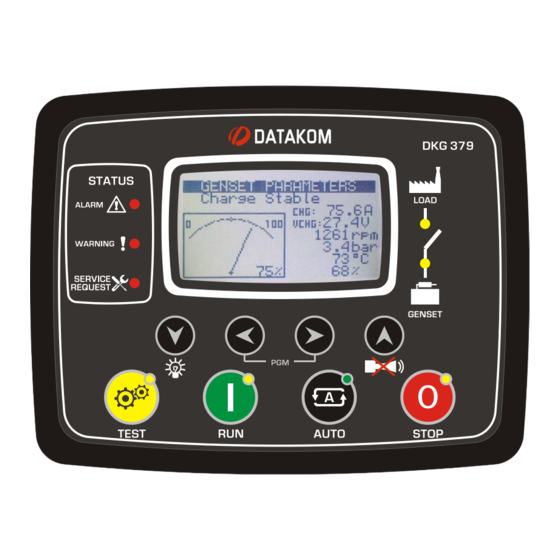
DKG-379 User Manual Rev_02 V-15 (24-12-2012) 7. DESCRIPTION OF CONTROLS 7.1. FRONT PANEL FUNCTIONALITY Graphic LCD Mimic Diagram screen Fault condition (sysem status) indicators Service request indicator Next display LAMP TEST if held pressed ALARM Mute Previous display TEST mode... -
Page 27: Pushbutton Functions
DKG-379 User Manual Rev_02 V-15 (24-12-2012) 7.2. PUSHBUTTON FUNCTIONS BUTTON FUNCTION Selects TEST mode. The genset runs and starts charging Selects RUN mode. The genset runs off-load. Selects AUTO mode. The genset runs when necessary and starts charging. Selects OFF mode. The genset stops. -
Page 28: Display Screen Organization
DKG-379 User Manual Rev_02 V-15 (24-12-2012) 7.3. DISPLAY SCREEN ORGANIZATION The unit has a graphical 128x64 pixel LCD display. It shows: -Measured parameters, -The company logo, -The alarm list -Software version and date-time information, -Statistical counters, -Event records, -Program parameters. - Page 29 DKG-379 User Manual Rev_02 V-15 (24-12-2012) Below screens are applicable to J1939 enabled versions only. Description Contents CANBUS Measurements Percent Torque 1 / 6 Percent Load Fuel Pressure CANBUS Measurements Fuel Rate 2 / 6 Average Fuel Economy Total Engine Hours...
-
Page 30: Led Lamps
DKG-379 User Manual Rev_02 V-15 (24-12-2012) 7.4. LED LAMPS Shutdown Load alarm indicator Contactor on led Warning indicator Genset running led Service request indicator RUN mode TEST mode AUTO mode STOP mode indicator indicator indicator indicator STATUS LEDS: ALARM: Turns on when a shutdown alarm or loaddump condition exists. -
Page 31: Displaying Event Logs
DKG-379 User Manual Rev_02 V-15 (24-12-2012) 8. DISPLAYING EVENT LOGS The unit features 100 event logs with date-time stamp and full snapshot of measured values at the moment that the event has occurred. Stored values in an event record are listed below:... - Page 32 DKG-379 User Manual Rev_02 V-15 (24-12-2012) Event logs are displayed within the program mode menu. This is designed in order to reduce the interference of event logs with other measurement screens. To enter the event display, press together buttons for 5 seconds.
-
Page 33: Statistical Counters
DKG-379 User Manual Rev_02 V-15 (24-12-2012) 9. STATISTICAL COUNTERS The unit provides a set of non resettable incremental counters for statistical purposes. The counters consist on: -total genset kWh -total engine hours -total engine cranks -total engine runs -engine hours to service -time to service These counters are kept in a non-volatile memory and are not affected from power failures. -
Page 34: Operation Of The Unit
DKG-379 User Manual Rev_02 V-15 (24-12-2012) 10. OPERATION OF THE UNIT 10.1. QUICK START GUIDE STOPPING THE ENGINE: Press STOP button STARTING THE ENGINE: Press RUN button MANUAL LOAD TRANSFER: Press TEST button. The genset will run and take the load. -
Page 35: Auto Mode
DKG-379 User Manual Rev_02 V-15 (24-12-2012) 10.3. AUTO MODE The AUTO mode is entered by pressing the button. The AUTO mode is used for the automatic charging of the battery bank. The controller will constantly monitor the battery bank voltage. It will run the engine and transfer the load when the voltage falls below programmed threshold. -
Page 36: Run Mode, Manual Control
DKG-379 User Manual Rev_02 V-15 (24-12-2012) 10.4. RUN MODE, MANUAL CONTROL The RUN mode is entered by pressing the button. When the RUN mode is selected, the engine will be immediately started. The starting sequence is as described below: •... -
Page 37: Optimal Charging, Variable Speed Operation
DKG-379 User Manual Rev_02 V-15 (24-12-2012) 11. OPTIMAL CHARGING, VARIABLE SPEED OPERATION It is strongly recommended to wire speed detection through MPU, charge alternator pulses or J1939- CANBUS and enter correct low and high rpm limit values in order to preserve engine speed protection. - Page 38 DKG-379 User Manual Rev_02 V-15 (24-12-2012) Parameter Definition, Factory Unit Description (Password Level) If this value is different from zero, when the charge current falls below this percentage of the max charge current, then the charge cycle will be supposed to be terminated.
-
Page 39: Optimal Charge Cycle Description
DKG-379 User Manual Rev_02 V-15 (24-12-2012) 11.2. OPTIMAL CHARGE CYCLE DESCRIPTION Below picture describes the charge cycle steps in detail. Step_A: The genset is at rest. The load consumes power from the battery bank. The battery bank voltage decreases slowly with discharge level. -
Page 40: Effect Of Battery Bank Temperature
DKG-379 User Manual Rev_02 V-15 (24-12-2012) The battery bank voltage increases slightly with charge percentage. Step_H: The rpm is controlled in order to keep the battery bank voltage at nominal boost voltage. The charge current decreases slowly. Step_J: When the charge current falls below the stop current percent, the controller decreases the rpm until charge current becomes zero, then opens the load contactor and decreases the rpm until idle speed. -
Page 41: Uncontrolled Charging, Fixed Speed Operation
DKG-379 User Manual Rev_02 V-15 (24-12-2012) 12. UNCONTROLLED CHARGING, FIXED SPEED OPERATION It is strongly recommended to wire speed detection through MPU, charge alternator pulses or J1939- CANBUS and enter correct low and high rpm limit values in order to preserve engine speed protection. -
Page 42: Uncontrolled Charge Cycle Description
DKG-379 User Manual Rev_02 V-15 (24-12-2012) 12.2. UNCONTROLLED CHARGE CYCLE DESCRIPTION Below picture describes the charge cycle steps in detail. Step_A: The genset is at rest. The load consumes power from the battery bank. The battery bank voltage decreases slowly with discharge level. -
Page 43: Protections And Alarms
DKG-379 User Manual Rev_02 V-15 (24-12-2012) 13. PROTECTIONS AND ALARMS The unit provides 3 different protection levels, being warnings, loaddumps and shutdown alarms. 1- SHUTDOWN ALARMS: These are the most important fault conditions and cause: The ALARM led to turn on steadily,... -
Page 44: Shutdown Alarms
DKG-379 User Manual Rev_02 V-15 (24-12-2012) 13.1. SHUTDOWN ALARMS Digital input alarms are fully programmable for the alarm name, sampling and action. Only internal alarms are explained in this section. GENSET LOW / HIGH Set if the engine rpm is outside programmed limits. These faults will be SPEED monitored with Holdoff Timer delay after the engine is running. -
Page 45: Loaddump Alarms
DKG-379 User Manual Rev_02 V-15 (24-12-2012) 13.2. LOADDUMP ALARMS Digital input and analog sender alarms are fully programmable for the alarm name, sampling and action. Only internal alarms are explained in this section. OVERLOAD Set if the alternator output current goes over the Overcurrent Limit for Overload Timer. -
Page 46: Warnings
DKG-379 User Manual Rev_02 V-15 (24-12-2012) 13.3. WARNINGS GENSET LOW / HIGH Set if the engine rpm is outside programmed limits. These faults will be SPEED monitored with Holdoff Timer delay after the engine is running. Low and high limits for warning and alarm are separately programmable. Another high engine rpm shutdown limit which is 12% above the high limit is always monitored and stops the engine immediately. -
Page 47: Programming
DKG-379 User Manual Rev_02 V-15 (24-12-2012) 14. PROGRAMMING 14.1. RESETTING TO FACTORY DEFAULTS In order to resume to the factory set parameter values: -hold pressed the OFF, LAMP TEST and ALARM MUTE buttons for 5 seconds, -“RETURN TO FACTORY SET” will be displayed -immediately press and hold pressed the ALARM MUTE button for 5 seconds -factory set values will be reprogrammed to the parameter memory. -
Page 48: Entering The Programming Mode
DKG-379 User Manual Rev_02 V-15 (24-12-2012) 14.2. ENTERING THE PROGRAMMING MODE ◄ ► To enter the program mode, press together MENU and MENU buttons for 5 seconds. When the program mode is entered, below password entry screen will be displayed. -
Page 49: Navigating Between Menus
DKG-379 User Manual Rev_02 V-15 (24-12-2012) 14.3. NAVIGATING BETWEEN MENUS The program mode is driven with a two level menu system. The top menu consists on program groups and each group consists on various program parameters. When program mode is entered, a list of available groups will be displayed. Navigation between different ▼... -
Page 50: Modifying Parameter Value
DKG-379 User Manual Rev_02 V-15 (24-12-2012) 14.4. MODIFYING PARAMETER VALUE Decrease Increase parameter parameter value value Previous parameter Long Press: Next Return to the parameter upper menu 14.5. PROGRAMMING MODE EXIT To exit the program mode press one of the mode selection keys. If no button is pressed during 2 minutes the program mode will be cancelled automatically. -
Page 51: Program Parameter List
DKG-379 User Manual Rev_02 V-15 (24-12-2012) 15. PROGRAM PARAMETER LIST 15.1. CONTROLLER CONFIGURATION GROUP Parameter Definition, Unit Factory Description (Password Level) This parameter is used to set LCD contrast. Adjust for (1) LCD Contrast the best viewing angle. 0: English language selected. - Page 52 1: temperature display in degrees F Delayed Simulate Mains Operation: max genset running time after Simulate Mains signal disappears. (2) Flashing Relay Timer hours Dual Genset Systems: flashing relay toggle timer. Please contact DATAKOM for dual genset mutual stanby operation. K43D01-EN - 52 -...
- Page 53 DKG-379 User Manual Rev_02 V-15 (24-12-2012) 15.1. CONTROLLER CONFIGURATION GROUP (continued) Parameter Definition, Unit Factory Description (Password Level) This parameter trims precisely the real time clock circuit. Values from 0 to 63 speed up the clock with (1) Real Time Clock Adjust 0.25sec/day steps.
-
Page 54: Electrical Parameters Group
DKG-379 User Manual Rev_02 V-15 (24-12-2012) 15.2. ELECTRICAL PARAMETERS GROUP Parameter Definition, Unit Factory Description (Password Level) This is the rated value of the current shunt at 60mV- (2) Current Shunt Rating DC output voltage. If the current goes above this limit, during the period... - Page 55 DKG-379 User Manual Rev_02 V-15 (24-12-2012) 15.2. ELECTRICAL PARAMETERS GROUP (continued) Parameter Definition, Factory Unit Description (Password Level) This is the maximum allowed temperature of the °C (1) Max Battery Temperature battery bank. If the temperature approaches this limit, then the charging current will be reduced.
- Page 56 DKG-379 User Manual Rev_02 V-15 (24-12-2012) 15.2. ELECTRICAL PARAMETERS GROUP (continued) Parameter Definition, Factory Unit Description (Password Level) When the battery bank voltage falls below the (1) Charge Voltage Battery Start to Charge Voltage during this timer, Threshold Timer then the controller will initiate an automatic charging cycle.
-
Page 57: Engine Parameters Group
DKG-379 User Manual Rev_02 V-15 (24-12-2012) 15.3. ENGINE PARAMETERS GROUP Parameter Definition, Factory Unit Description (Password Level) If the oil pressure measured from the analog input (1) Low Oil Pressure falls below this limit, this will generate a LOW OIL Warning PRESSURE SENDER warning. - Page 58 DKG-379 User Manual Rev_02 V-15 (24-12-2012) 15.3. ENGINE PARAMETERS GROUP (continued) Parameter Definition, Unit Factory Description (Password Level) This is the maximum time duration for the engine to stop. During this period the STOP relay output is (1) Stop Solenoid Timer energized (if assigned by Relay Definitions).
- Page 59 DKG-379 User Manual Rev_02 V-15 (24-12-2012) 15.3. ENGINE PARAMETERS GROUP (continued) Parameter Definition, Unit Factory Description (Password Level) If the engine speed goes under this limit, a GENSET (2) Low rpm Shutdown LOW SPEED alarm is generated and the engine stops.
- Page 60 DKG-379 User Manual Rev_02 V-15 (24-12-2012) 15.3. ENGINE PARAMETERS GROUP (continued) Below parameters are applicable to J1939 enabled versions only. Parameter Definition, Unit Factory Description (Password Level) 0: The J1939 port is inoperative. 1: The analog measurements (oil, temp, rpm) are (2) J1939 Enable picked_up from the ECU.
-
Page 61: Adjust Date And Time
DKG-379 User Manual Rev_02 V-15 (24-12-2012) 15.4. ADJUST DATE AND TIME These parameters allow adjusting the battery backup real time clock of the module. Once set, the clock will continue to run even if DC power is removed from the unit. -
Page 62: Sender Characteristics
DKG-379 User Manual Rev_02 V-15 (24-12-2012) 15.6. SENDER CHARACTERISTICS Parameter Definition Unit Factory Description Oil Pressure Sender point 1, ohm value Oil Pressure Sender Ohms -1 Oil Pressure Sender point 1, bar value Oil Pressure Value -1 Oil Pressure Sender point 2, ohm value... - Page 63 DKG-379 User Manual Rev_02 V-15 (24-12-2012) Parameter Definition Unit Factory Description Fuel Level Sender point 1, ohm value Fuel Level Sender Ohms -1 Fuel Level Sender point 1, % value Fuel Level Value -1 Fuel Level Sender point 2, ohm value...
-
Page 64: Input Configuration
DKG-379 User Manual Rev_02 V-15 (24-12-2012) 15.7. INPUT CONFIGURATION (Low Oil Pressure Switch) (password level-2) Parameter Definition Unit Fac.Set Description 0: Shutdown (the engine stops immediately) 1: Load Dump (the engine stops after cooldown) Action 2: Warning (the horn relay operates) - Page 65 DKG-379 User Manual Rev_02 V-15 (24-12-2012) 15.7. INPUT CONFIGURATION (Coolant Level Switch) (password level-2) Parameter Definition Unit Fac.Set Description 0: Shutdown (the engine stops immediately) 1: Load Dump (the engine stops after cooldown) Action 2: Warning (the horn relay operates)
- Page 66 DKG-379 User Manual Rev_02 V-15 (24-12-2012) 15.7. INPUT CONFIGURATION (Emergency Stop) (password level-2) Parameter Definition Unit Fac.Set Description 0: Shutdown (the engine stops immediately) 1: Load Dump (the engine stops after cooldown) Action 2: Warning (the horn relay operates) 3: No operation...
- Page 67 DKG-379 User Manual Rev_02 V-15 (24-12-2012) 15.7. INPUT CONFIGURATION (Spare-2 Input) (password level-2) Parameter Definition Unit Fac.Set Description 0: Shutdown (the engine stops immediately) 1: Load Dump (the engine stops after cooldown) Action 2: Warning (the horn relay operates) 3: No operation...
-
Page 68: Relay Definitions
DKG-379 User Manual Rev_02 V-15 (24-12-2012) 15.8. RELAY DEFINITIONS (password level-2) The parameters below define the functions of relay outputs. The unit has 6 relay outputs. The fixed function relays are Fuel, Start and Generator Contactor. RELAY-1 and RELAY-2 have programmable functions, selected from a list. - Page 69 DKG-379 User Manual Rev_02 V-15 (24-12-2012) The function of a programmable relay output may be selected from the below list. Fuel Oil switch alarm Oil switch warning Alarm Temp switch alarm Temp switch warn. Start Coolant Level switch Coolant Level switch...
-
Page 70: Input Function Select
DKG-379 User Manual Rev_02 V-15 (24-12-2012) 15.9. INPUT FUNCTION SELECT (password level-2) The parameters below define the functions of digital inputs, selected from a list. Functions from 12 to 23 activate also the related operating sequence. The related input configuration parameters apply for each input, thus any signal can be programmed for NO or NC contact, closing to BAT+ or BAT-. -
Page 71: Site Id String
DKG-379 User Manual Rev_02 V-15 (24-12-2012) 15.10. SITE ID STRING Parameter Definition Factory Set Description This is the site Id string sent at the beginning of an DATAKOM SITE SMS message for the identification of the genset Site Id String sending the SMS message. - Page 72 DKG-379 User Manual Rev_02 V-15 (24-12-2012) Program Group: SMS-3 Telephone Number (password level-2) Parameter Definition Factory Set Description ---------------- This SMS telephone number accepts up to 16 digits. SMS-3 telephone number Program Group: SMS-4 Telephone Number (password level-2) Parameter Definition...
-
Page 73: Crank Cutting
DKG-379 User Manual Rev_02 V-15 (24-12-2012) 16. CRANK CUTTING In order to insure fast and reliable crank cutting, the unit uses various resources for engine running condition detection. Cranking is stopped when at least one of below conditions is met: - Crank timer expired: The crank timer is adjusted through Engine Parameters >... -
Page 74: J1939 Canbus Engine Support
Type parameter should be set accordingly. The list of available engines is given at the programming section. Please contact DATAKOM for the most current list of engines. If the J1939 port is enabled then the oil pressure, coolant temperature and the engine rpm information are picked up from the ECU unit. - Page 75 DKG-379 User Manual Rev_02 V-15 (24-12-2012) Below is a basic list of fault conditions (x denotes any FMI) DESCRIPTION Fuel filter restriction Fuel pressure sensor fail Low oil level High oil level Oil level sensor fail Low oil pressure Oil pressure sensor fail...
- Page 76 DKG-379 User Manual Rev_02 V-15 (24-12-2012) Below is a basic list of FMI codes. Please be aware that these codes may differ slightly depending on the engine brand and model. DESCRIPTION Value too high” Valid data, but above the normal working range “Value too low”...
-
Page 77: Software Features
2 minutes. 18.2. Speed UP/DOWN Relay Outputs The DKG-379 is able to control the engine rpm through a motorized potentiometer using its speed up/down output functions. In order to use speed up/down output functions, corresponding digital output functions of the Relay Definitions group should be set properly. -
Page 78: Remote Start Operation
DKG-379 User Manual Rev_02 V-15 (24-12-2012) 18.3. Remote Start Operation The unit offers the possibility of Remote Start mode of operation. Any digital input may be assigned as Remote Start Input using Input Function Select program parameters. The Remote Start signal may be a NO or NC contact, switching to either battery positive or battery negative. -
Page 79: Dual Genset Mutual Standby Operation
If a Priority input is defined, then the system will work in priority mode. If the priority signal is applied, the unit will become master. If the priority signal is not applied, then the unit will become the slave one and the other genset will start. Please contact DATAKOM for a complete application manual. K43D01-EN... -
Page 80: External Control Of The Unit
DKG-379 User Manual Rev_02 V-15 (24-12-2012) 18.6. External Control of the Unit The unit offers total external control through programmable digital inputs. Any digital input may be programmed for below functions: - Force STOP mode - Force AUTO mode - Force TEST mode... -
Page 81: Weekly Operation Scheduler
DKG-379 User Manual Rev_02 V-15 (24-12-2012) 18.8. Weekly Operation Scheduler In most applications, the genset is requested to operate only in working hours. Thanks to the weekly program feature, unwanted operation of the genset may be prohibited. The scheduler is active only in AUTO mode. When the scheduler prevents genset operation in AUTO mode, the AUTO led will flash. -
Page 82: Engine Block Heater
DKG-379 User Manual Rev_02 V-15 (24-12-2012) 18.11. Engine Block Heater The unit is able to provide a digital output in order to drive the block heater resistor. The temperature reference is the coolant temperature measured from the analog sender input. -
Page 83: Modbus Support
DKG-379 User Manual Rev_02 V-15 (24-12-2012) 19. MODBUS SUPPORT The unit offers the possibility of MODBUS communication via its RS232 serial port. The connection to the MODBUS master may be done in 3 ways: 1) RS232 connection using directly the RS232 port provided. - Page 84 DKG-379 User Manual Rev_02 V-15 (24-12-2012) ADDRESS DATA COEFFICIENT DESCRIPTION (hex) SIZE 0032 16bit Shutdown alarm bits bit_0: oil pressure switch shutdown alarm bit_1: high temperature switch shutdown alarm bit_2: coolant level switch shutdown alarm bit_3: rectifier fail shutdown alarm...
- Page 85 DKG-379 User Manual Rev_02 V-15 (24-12-2012) ADDRESS DATA COEFFICIENT DESCRIPTION (hex) SIZE 0037 8bit Warning bits bit_0: service request warning bit_2:low engine battery voltage fail bit_3: high engine battery voltage warning bit_4: charge fail warning bit_5: ECU fail warning 0038...
- Page 86 DKG-379 User Manual Rev_02 V-15 (24-12-2012) ADDRESS DATA COEFFICIEN DESCRIPTION (hex) SIZE 003C 16bit Relay function statuses bit_0: battery bank voltage below threshold bit_1: block heater on bit_2: service request bit_5: flashing relay output bit_6: gas solenoid bit_7: fuel pump...
- Page 87 DKG-379 User Manual Rev_02 V-15 (24-12-2012) ADDRESS DATA COEFFICIE DESCRIPTION (hex) SIZE 005A- 40bit 0.01 Engine run hours since last service, coded in 5 bytes. 005B-005C First 2 bytes (register 005Ah) contain binary flags. Last 3 bytes contain engine hours multiplied by 0.16 hours.
- Page 88 DKG-379 User Manual Rev_02 V-15 (24-12-2012) ADDRESS DATA COEFFICIENT DESCRIPTION (hex) SIZE 1025 8bit Operation mode_1 bits: bit_0:engine heating method bit_1:- bit_2:charge alternator shutdown bit_3:- bit_4:L-L voltage display bit_5:emergency backup operation bit_6:- bit_7:intermittent alarm output 1026 8bit Operation mode_2 bits:...
-
Page 89: Declaration Of Conformity
“Monitoring and control instruments including industrial monitoring and control instruments” and exempted from ROHS directive. However Datakom is not using any ROHS uncompliant electronic components in the production. Only the solder contains lead. The switching to unleaded solderin is in progress. K43D01-EN... -
Page 90: Troubleshooting Guide
DKG-379 User Manual Rev_02 V-15 (24-12-2012) 24. TROUBLESHOOTING GUIDE Below is a basic list of most often encountered troubles. More detailed investigation may be required in some cases. AUTO led flashes and the genset does not run when mains fail: The unit is in Weekly Schedule OFF time. - Page 91 DKG-379 User Manual Rev_02 V-15 (24-12-2012) Some program parameters are skipped: These parameters are reserved for factory setting and cannot be modified. The genset runs but does not take the load: Check that the genset Yellow led is on steadily. Adjust genset voltage and frequency limits if necessary.
Need help?
Do you have a question about the DKG-379 and is the answer not in the manual?
Questions and answers