Table of Contents
Advertisement
Quick Links
DKG-325 User Manual
DESCRIPTION
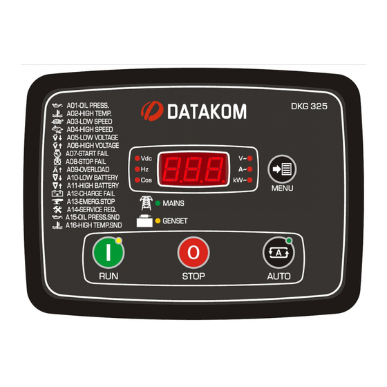
DKG-325, is a ready-to-use control and transfer panel
for gasoline and diesel gensets rated up to 15kVA. It
supports both 1 and 3 phase gensets.
The unit incorporates all necessary components for
battery charging, genset control and load transfer
between mains and genset.
Gensets may be automatized using the DKG-325,
without the need for any additional equipment. Thanks
to the unit, automatization of small gensets has become
easy and cost effective.
In AUTO position, the unit monitors 3 phases of the
mains, runs and stops the genset automatically and
performs load transfer. When the engine is running, it
monitors internal protections and alarm inputs.
The unit features 2 contactors, battery charging rectifier
and the automatic control circuitry in one enclosure. It is
the equivalent of a complete genset control panel.
Internal contactors are rated for 40Amp switching and
are capable of carrying 25Amp continuously.
Fuel and crank outputs are provided through 40Amp
rated relays and do not require additional relays.
The internal battery charging rectifier is rated 1Amp
@12V-DC. The internal rectifier is sufficient for the float
charging of the engine start battery.
The unit features 3 internal current transformers. It
measures currents and power from both genset and
mains.
Timers, threshold levels, input and output configurations
are digitally programmable. Programs are modified
through front panel pushbuttons and do not require an
additional unit.
Firmware V-56
DKG-325
GENSET
CONTROL &
ATS PANEL
FEATURES
•
Automatic mains monitoring
•
Automatic load transfer
•
Automatic starting and stopping
•
Automatic stopping in fault condition
•
Test mode available
•
Emergency backup mode
•
Internal current transformers
•
Detailed load measurements and
protections
•
Internal battery charging rectifier
•
40 Amp rated Fuel and Crank outputs
•
Front panel adjustable parameters
•
Stop, preheat and choke output capability
•
Configurable spare digital input
•
Survives cranking voltage dropouts
•
Compact dimensions, flush mounted
MEASUREMENTS
Mains Voltages: L1-N, L2-N, L3-N
Mains Voltages: L1-L2, L2-L3, L3-L1
Genset Voltages: L1-N, L2-N, L3-N
Genset Voltages: L1-L2, L2-L3, L3-L1
Load Currents: L1, L2, L3
Load phase and total kW, kVA, kVAr, cosΦ
Genset Frequency
Battery Voltage
Oil pressure
Coolant temperature
Engine run Hours
Service Counters
Advertisement
Table of Contents

Related Manuals for Datakom DKG-325


Summary of Contents for Datakom DKG-325
- Page 1 GENSET CONTROL & ATS PANEL DESCRIPTION FEATURES • DKG-325, is a ready-to-use control and transfer panel Automatic mains monitoring for gasoline and diesel gensets rated up to 15kVA. It • Automatic load transfer supports both 1 and 3 phase gensets.
- Page 2 DKG-325 family units. Follow carefully advices given in the document. These are often good practices for the installation which reduce future issues. For all technical queries please contact Datakom at below e-mail address: datakom@datakom.com.tr QUERRIES If additional information to this manual is required, please contact the manufacturer directly at below e- mail address: datakom@datakom.com.tr...
- Page 3 DKG-325 User Manual Firmware V-56 ORDER CODES DKG325 is available in various options and peripheral features. Please use below information for ordering the correct version: DKG325 -G -T -00 Variant 00: standard unit 01...99: customer Conformal Product Code Watertight specific products...
- Page 4 DKG-325 User Manual Firmware V-56 SAFETY NOTICE Failure to follow below instructions will result in death or serious injury Electrical equipment should be installed only by qualified specialist. No responsibility is assured by the manufacturer or any of its subsidiaries for any consequences resulting from the non-compliance to these instructions.
-
Page 5: Table Of Contents
DKG-325 User Manual Firmware V-56 TABLE OF CONTENTS 1. INSTALLATION INSTRUCTIONS 2. MOUNTING 2.1 DIMENSIONS 2.2 SEALING, GASKET 2.3 ELECTRICAL INSTALLATION 3. TERMINAL DESCRIPTIONS 3.1. BATTERY VOLTAGE INPUT 3.2. AC VOLTAGE INPUTS 3.3. DIGITAL INPUTS 3.4. ANALOG SENDER INPUTS 3.5. CHARGE INPUT TERMINAL 3.6. - Page 6 DKG-325 User Manual Firmware V-56 TABLE OF CONTENTS (continued) 12. SOFTWARE FEATURES 12.1. REMOTE START OPERATION 12.2. MAINS SIMULATION 12.3. DELAYED MAINS SIMULATION, BATTERY CHARGING 12.4. SERVICE REQUEST DISPLAY 12.5. ENGINE HOUR METER 12.6. SOFTWARE VERSION DISPLAY 12.7. GAS ENGINE FUEL SOLENOID CONTROL 12.8.
-
Page 7: Installation Instructions
DKG-325 User Manual Firmware V-56 1. INSTALLATION INSTRUCTIONS Before installation: Read the user manual carefully, determine the correct connection diagram. Remove all connectors and mounting brackets from the unit, then pass the unit through the mounting opening. ... -
Page 8: Mounting
DKG-325 User Manual Firmware V-56 2. MOUNTING 2.1. DIMENSIONS Dimensions: 200x148x72mm (7.9”x5.8”x2.9”) Panel cutout: 176x121mm minimum (7.0”x4.8”) Weight: 700g (1.5 lb) Mount the unit on a flat, vertical surface. Before mounting, remove the mounting brackets and connectors from the unit, then pass the unit through the mounting opening. - Page 9 DKG-325 User Manual Firmware V-56 The module will come with one of below bracket types: Spring type bracket Screw type bracket Screw type bracket installation Spring type bracket installation Do not tighten too much, this may break the unit. - 9 -...
-
Page 10: Sealing, Gasket
DKG-325 User Manual Firmware V-56 2.2. SEALING, GASKET Panel Gasket Module The rubber gasket provides a watertight means of mounting the module to the genset panel. Together with the gasket, 60529-IP65 protection can be reached from the front panel. A short definition of IP protection levels is given below. -
Page 11: Electrical Installation
DKG-325 User Manual Firmware V-56 2.3. ELECTRICAL INSTALLATION Do not install the unit close to high electromagnetic noise emitting devices like contactors, high current busbars, switchmode power supplies and the like. Although the unit is protected against electromagnetic disturbance, excessive disturbance can affect the operation, measurement precision and data communication quality. -
Page 12: Terminal Descriptions
DKG-325 User Manual Firmware V-56 3. TERMINAL DESCRIPTIONS 3.1. BATTERY VOLTAGE INPUT Battery terminals are both internal battery charger outputs and battery supply inputs. When AC mains supply is available, the unit charges the battery. When mains voltages fail, the unit continues operation through the engine battery. -
Page 13: Digital Inputs
DKG-325 User Manual Firmware V-56 3.3. DIGITAL INPUTS Contact type: Normally open or normally closed (programmable) Switching: Battery negative or battery positive (programmable) Structure: 47 k-ohms resistor to battery positive, 110k-ohms to battery negative. Measurement: Analog voltage measurement. Open circuit voltage:... -
Page 14: Charge Input Terminal
DKG-325 User Manual Firmware V-56 3.5. CHARGE INPUT TERMINAL The Charge terminal is both an input and output. When the engine is ready to run, this terminal supplies the excitation current to the charge alternator. The excitation circuit is equivalent to a 2W lamp. -
Page 15: Connection Diagram
DKG-325 User Manual Firmware V-56 4. CONNECTION DIAGRAM - 15 -... -
Page 16: Terminal Description
DKG-325 User Manual Firmware V-56 5. TERMINAL DESCRIPTION Term Function Technical data Description MAINS NEUTRAL Input, 0-250V-AC Neutral terminal for the mains phases. MAINS-L1 Mains phase inputs, Connect the mains phases to these inputs. MAINS-L2 0-250V-AC The mains voltages upper and lower limits are programmable. -
Page 17: Technical Specifications
DKG-325 User Manual Firmware V-56 6. TECHNICAL SPECIFICATIONS DC Supply Range: 9.0 - 16.0 V-DC. DC supply current: 250 mA-DC typical @12V-DC 500 mA-DC max. @12V-DC Alternator Voltage: 0-250 V-AC (Phase-Neutral) Alternator Frequency: 0-100 Hz. Mains Voltage: 0-250 V-AC (Phase-Neutral) Mains Frequency: 0-100 Hz. -
Page 18: Description Of Controls
DKG-325 User Manual Firmware V-56 7. DESCRIPTION OF CONTROLS 7.1. FRONT PANEL FUNCTIONALITY Mimic Diagram (system status) Menu selection button STOP mode AUTO mode RUN mode button button button 7.2. PUSHBUTTON FUNCTIONS BUTTON FUNCTION Selects RUN mode. The genset runs off-load. -
Page 19: Display Screen Organization
DKG-325 User Manual Firmware V-56 7.3. DISPLAY SCREEN ORGANIZATION The unit measures a large number of electrical and engine parameters. The display of the parameters is organized as a list which can be scanned by pressing the MENU button. Each depression of the button will cause the display to switch to the next parameter. -
Page 20: Led Indicators
DKG-325 User Manual Firmware V-56 7.5. LED INDICATORS Display unit leds Mains led. Flashes when mains is OK, turns-on steady when load is fed by mains. Genset led. Flashes when genset is running, turns-on steady when load is fed by the genset. -
Page 21: Operation Of The Unit
DKG-325 User Manual Firmware V-56 8. OPERATION OF THE UNIT 8.1. QUICK START GUIDE STOPPING THE GENSET: Press STOP button STARTING THE GENSET: Press RUN button AUTOMATIC OPERATION: Press AUTO button. Mode can be changed anytime without negative effect. Changing the operation mode while the genset is running will result into a behavior suitable for the new operating mode. -
Page 22: Auto Moden
DKG-325 User Manual Firmware V-56 8.4. AUTO MODE The AUTO mode is entered by pressing the button. The AUTO mode is used for the automatic transfer between genset and mains. The controller will constantly monitor the mains availability. It will run the engine and transfer the load when a mains failure occurs. -
Page 23: Protections And Alarms
DKG-325 User Manual Firmware V-56 9. PROTECTIONS AND ALARMS The unit provides 3 different protection levels, being warnings, loaddumps and shutdown alarms. 1- SHUTDOWN ALARMS: These are the most important fault conditions and cause: The display to show the alarm code,... -
Page 24: Service Request Alarm
DKG-325 User Manual Firmware V-56 9.1. SERVICE REQUEST ALARM The SERVICE REQUEST warning is designed to help the periodic maintenance of the genset to be made consistently. The periodic maintenance is basically carried out after a given engine hours (for example 200 hours), but even if this amount of engine hours is not fulfilled, it is performed after a given time limit (for example 12 months). -
Page 25: Alarms
DKG-325 User Manual Firmware V-56 9.2. ALARMS A01-LOW OIL PRESSURE: Set if a signal is detected at the Low Oil Pressure Switch. This fault will be monitored with Holdoff Timer delay after the engine is running. A02-HIGH TEMPERATURE: Set if a signal is detected at the High Temperature Switch input. -
Page 26: Programming
DKG-325 User Manual Firmware V-56 10. PROGRAMMING The program mode is used to program timers, operational limits and the configuration of the unit. To enter the program mode, hold pressed the MENU button for 10 seconds. When the program mode is entered, if the MENU button is pressed, the display will indicate the program parameter number. - Page 27 DKG-325 User Manual Firmware V-56 Parameter Name Unit Std. Description Fuel output type 0: activate to start P_01 1: activate to stop Oil switch type 0: oil pressure switch P_02 1: oil level switch 0: tri phased Single phase operation...
- Page 28 DKG-325 User Manual Firmware V-56 Parameter Definition Unit Fact.Set Description If one of the generator phase voltages goes under Genset Low Voltage this limit when feeding the load, this will generate a P_15 Shutdown Limit GENSET LOW VOLTAGE shutdown alarm and the engine will stop.
- Page 29 DKG-325 User Manual Firmware V-56 Parameter Definition Unit Fact.Set Description This is the period after the mains contactor has Genset Contactor P_32 been deactivated and before the generator Timer contactor has been activated. This is the period after the generator contactor has...
- Page 30 DKG-325 User Manual Firmware V-56 Parameter Definition Unit Fact.Set Description If the oil pressure measured from the analog input Low Oil Pressure P_49 falls below this limit, this will generate a LOW OIL Warning PRESSURE SENDER warning. If the oil pressure measured from the analog input...
- Page 31 DKG-325 User Manual Firmware V-56 Oil Pressure Sender Characteristics Parameter Definition Unit Factory Set Description P_53 Oil Pressure Sender point 1, ohm value Oil Pressure Sender Ohms -1 Oil Pressure Sender point 1, bar value P_54 Oil Pressure Value -1...
- Page 32 DKG-325 User Manual Firmware V-56 The parameters below define the function of the auxiliary relay output. The relay function is selected from below list. Program Group: Relay Definitions Parameter Definition Unit Fac.Set Description RELAY-1 function selected from list P_83 Relay 01 Definition...
-
Page 33: Crank Cutting
DKG-325 User Manual Firmware V-56 11. CRANK CUTTING In order to insure fast and reliable crank cutting, the unit uses various resources for engine running condition detection. Cranking is stopped when at least one of below conditions is met: - Crank timer expired: The crank timer is adjusted through programming menu. -
Page 34: Software Features
DKG-325 User Manual Firmware V-56 12. SOFTWARE FEATURES 12.1 Remote Start Operation The unit offers the possibility of REMOTE START mode of operation. The SPARE input may be assigned as Remote Start Input using the program parameter P_45. The REMOTE START signal may be a NO or NC contact, switching to either battery positive or battery negative. -
Page 35: Delayed Mains Simulation, Battery Charging
DKG-325 User Manual Firmware V-56 12.3 Delayed Mains Simulation, Battery Charging The Delayed Mains Simulation feature is used in battery backed up telecom systems where batteries are able to supply the load during a certain period. The genset is requested to run only when battery voltage drops below the critical level. -
Page 36: Service Request Display
DKG-325 User Manual Firmware V-56 12.4 Service Request Display This led is designed to help the periodic maintenance of the genset to be made consistently. The periodic maintenance is basically carried out after a given engine hours (for example 200 hours), but even if this amount of engine hours is not fulfilled, it is performed after a given time limit (for example 12 months). - Page 37 DKG-325 User Manual Firmware V-56 12.7 Gas Engine Fuel Solenoid Control The unit provides a special function for the fuel solenoid control of a gas engine. The fuel solenoid of a gas engine is different from a diesel engine. It should be opened after the cranking has been started and should be closed between crank cycles.
-
Page 38: Declaration Of Conformity
ROHS directive. However Datakom is not using any ROHS uncompliant electronic components in the production. Only the solder contains lead. The switching to unleaded solderin is in progress. - 38 -... -
Page 39: Troubleshooting
DKG-325 User Manual Firmware V-56 17. TROUBLESHOOTING Below is a basic list of most often encountered troubles. More detailed investigation may be required in some cases. The genset operates while AC mains are OK or continues to operate after AC mains are OK: -Check engine body grounding. - Page 40 The genset runs but does not take the load: Check that the genset led is flashing. Adjust genset voltage and frequency limits if necessary. Check “Genset Contactor Timer” program parameter. DATAKOM Electronics Ltd. Tel: +90-216-466 84 60 Fax: +90-216-364 65 65 e-mail: datakom@datakom.com.tr http: www.datakom.com.tr - 40 -...
Need help?
Do you have a question about the DKG-325 and is the answer not in the manual?
Questions and answers