Table of Contents
Advertisement
DKG-307 User Manual
DKG-307 AUTOMATIC MAINS FAILURE AND
Automatic mains failure,
Engine control,
Generator protection,
Built in alarms and warnings,
3 phase mains voltage inputs
3 phase genset voltage inputs
3 phase genset CT inputs
Engine oil pressure measurement
Engine coolant temperature measurement
Genset active power measurement
Genset power factor measurement
Periodic maintenance request indicator
Daily / weekly / monthly exerciser
Engine hours counter
Event logging
Statistical counters
Battery backed-up real time clock
Weekly operation schedule programs
REMOTE START UNIT
FEATURES
e-mail : mercuris@mail.ru
http: www.mercuris.ru
Field adjustable parameters
RS-232 serial port
Free MS-Windows Remote monitoring SW:
-local, LAN, IP and modem connection
-monitoring, download of parameters
LED displays
Configurable analogue inputs: 2
Configurable digital inputs: 7
Configurable relay outputs: 2
Total relay outputs: 6
I/O expansion capability
Remote Start operation available
Simulate Mains operation available
Survives cranking dropouts
Sealed front panel
Plug-in connection system for easy replacement
Small dimensions (165x125x48mm)
Low cost
V-01.13
(08.04.2008)
Advertisement
Table of Contents

Related Manuals for Datakom DKG-307


Summary of Contents for Datakom DKG-307
- Page 1 DKG-307 User Manual V-01.13 (08.04.2008) e-mail : mercuris@mail.ru http: www.mercuris.ru DKG-307 AUTOMATIC MAINS FAILURE AND REMOTE START UNIT FEATURES Automatic mains failure, Field adjustable parameters Engine control, RS-232 serial port Generator protection, Free MS-Windows Remote monitoring SW: Built in alarms and warnings,...
-
Page 2: Table Of Contents
DKG-307 User Manual V-01.13 (08.04.2008) TABLE OF CONTENTS Section 1. INSTALLATION 1.1. Introduction to the Control Panel 1.2. Mounting the Unit 1.3. Wiring the Unit 2. INPUTS AND OUTPUTS 3. DISPLAYS 3.1. Led Displays 3.2. Digital Display 4. ALARMS AND WARNINGS 5. -
Page 3: Installation
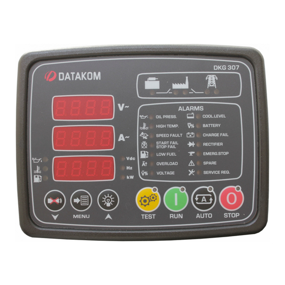
DKG-307 User Manual V-01.13 (08.04.2008) 1. INSTALLATION 1.1 Introduction to the Control Panel The unit is a control and protection panel used in gensets. It shows the measured values on its displays. The unit is designed to provide user friendliness for both the installer and the user. Programming is usually unnecessary, as the factory settings have been carefully selected to fit most applications. -
Page 4: Wiring The Unit
DKG-307 User Manual V-01.13 (08.04.2008) 1.3 Wiring the Unit WARNING: THE UNIT IS NOT FUSED. Use external fuses for Mains phases: R-S-T Generator phase: U-V-W Battery positive: BAT(+). Install the fuses as nearly as possible to the unit in a place easily accessible for the user. - Page 5 DKG-307 User Manual V-01.13 (08.04.2008) Term Function Technical data Description MAINS CONTACTOR Relay output, 16A-AC This output provides energy to the mains contactor. If the mains phases do not have acceptable voltages, the mains contactor will be de-energized. In order to provide extra...
-
Page 6: Displays
DKG-307 User Manual V-01.13 (08.04.2008) 3. DISPLAYS 3.1 Led Displays The unit has 29 LEDs, divided in 4 groups: -Group_1: Operating mode: This group indicates the genset function. -Group_2: Mimic diagram: This group indicates the current status of the mains and genset voltages and contactors. -
Page 7: Digital Display
DKG-307 User Manual V-01.13 (08.04.2008) 3.2 Digital Displays The unit has 3 seven segment displays. They show: -Measured parameters, -Service counters, -Statistical counters, -Program parameters. The navigation between different screens in a group is made with the MENU button. Holding the MENU button pressed for 1 second makes the display to switch to the next group. -
Page 8: Alarms And Warnings
DKG-307 User Manual V-01.13 (08.04.2008) 4. ALARMS AND WARNINGS Alarms indicate an abnormal situation in the generating set are divided into 2 priority levels: 1- ALARMS: These are the most important fault conditions and cause: The related alarm led to be on steadily,... -
Page 9: Modes Of Operation
DKG-307 User Manual V-01.13 (08.04.2008) 5. MODES OF OPERATION The modes of operation are selected by pushing the front panel keys. Changing the operation mode while the genset is running will result to a behavior suitable for the new operating mode. For example, if the LOAD TEST mode is selected when genset is running at TEST mode, then the genset will take the load. -
Page 10: Sender Type Selection
DKG-307 User Manual V-01.13 (08.04.2008) 6.2 Sender type Selection The unit has the ability to adapt to any type of oil pressure and temperature senders. The commonly used standard sender characteristics are recorded in memory and selectable from a list. -
Page 11: Service Request Display
DKG-307 User Manual V-01.13 (08.04.2008) 6.4 Service Request Display This led is designed to help the periodic maintenance of the genset to be made consistently. The periodic maintenance is basically carried out after a given engine hours (for example 200 hours), but even if this amount of engine hours is not fulfilled, it is performed after a given time limit (for example 12 months). -
Page 12: Remote Monitoring And Programming
DKG-307 User Manual V-01.13 (08.04.2008) 6.7 Remote Monitoring and Programming Thanks to its standard serial RS-232 port, the unit offers the remote monitoring and programming feature. remote monitoring programming software downloaded from www.datakom.com.tr internet site. The software allows the visualization and recording of all measured parameters. The recorded parameters may then be analyzed graphically and printed. -
Page 13: Simulate Mains
DKG-307 User Manual V-01.13 (08.04.2008) 6.9 Simulate Mains The unit offers an optional SIMULATE MAINS signal input. If the program parameter P_050 is set to 1 then the SPARE_2 (22) input will be used for mains simulation. It is also necessary to set the program parameter P_119 to 3 in order to prevent any alarm generated from this input. -
Page 14: Weekly Operation Schedule
DKG-307 User Manual V-01.13 (08.04.2008) 7. WEEKLY OPERATION SCHEDULE In most applications, the genset is requested to operate only in working hours. Thanks to the weekly program feature unwanted operation of the genset may be prohibited. The unit has one programmable turn-on/turn-off time pairs for each day of week. These programmable parameters allow the genset to operate automatically only in allowed time limits. -
Page 15: Event Logging
DKG-307 User Manual V-01.13 (08.04.2008) 8. EVENT LOGGING The unit keeps records of the last 12 events in order to supply information for the service personal. The events are recorded with a date and time stamp. The date and time information comes from the internal battery backed-up real time clock circuit of the unit. -
Page 16: Programming
DKG-307 User Manual V-01.13 (08.04.2008) 10. PROGRAMMING The program mode is used to program the timers, operational limits and the configuration of the unit. To enter the program mode, press the MENU button for 5 seconds. The program mode is only allowed if the PROGRAM LOCK input (terminal_23) is left open. - Page 17 DKG-307 User Manual V-01.13 (08.04.2008) Definition Unit Std Val Description If the genset frequency goes under this limit, a SPEED alarm will be generated and the engine Low Freq. Alarm will stop. This alarm will be monitored after delay defined in P_023 when the engine runs.
- Page 18 DKG-307 User Manual V-01.13 (08.04.2008) Definition Unit Std Val Description Hysteresis Voltage This parameter provides the mains and genset voltage limits with a hysteresis feature in order to prevent faulty decisions. For example, when the mains are present, the mains voltage low limit will be used as the programmed low limit P_004.
- Page 19 DKG-307 User Manual V-01.13 (08.04.2008) Definition Unit Std Val Description Horn Timer This is the period during which the HORN relay is active. If the period is set to 0, this will mean that the period is unlimited. Engine Heating Type This parameter defines the engine heating method.
- Page 20 DKG-307 User Manual V-01.13 (08.04.2008) The parameters from P_051 to P_064 program the weekly operation schedule feature. For each day of week, one turn_on time and one turn_off time are provided. Times are defined with 10 minute steps and are shown in the 3 digit display as the hours and the first digit of the minutes. If no operation is needed for a certain day of week, then the related time will be defined as 24.0;...
- Page 21 DKG-307 User Manual V-01.13 (08.04.2008) Parameters from P_083 to P_130 program the functions of the digital inputs. The programmable properties of digital inputs are: -action to be taken upon arrival of the fault signal (alarm, warning,etc...), -when the fault monitoring will be enabled,...
- Page 22 DKG-307 User Manual V-01.13 (08.04.2008) RECTIFIER FAIL INPUT Description Operation 0: Alarm (the engine stops and horn relay operates)) 2: Warning (the horn relay operates) 3: No operation 0: Always Fault monitoring 1: After holdoff timer 2: When mains present...
- Page 23 DKG-307 User Manual V-01.13 (08.04.2008) SPARE-2 FAULT INPUT Description Operation 0: Alarm (the engine stops and horn relay operates)) 2: Warning (the horn relay operates) 3: No operation Fault monitoring 0: Always 1: After holdoff timer 2: When mains present...
- Page 24 DKG-307 User Manual V-01.13 (08.04.2008) Parameters from P_143 to P_154 define the ohm-degrees characteristics of the temperature sender. The sender characteristics will be defined using maximum 6 points. The values should be entered in the increasing order of ohm values. For unused points, ohm values should be entered as 0. An example table is given below.
- Page 25 DKG-307 User Manual V-01.13 (08.04.2008) The parameters from P_155 to P_158 define the exerciser operation. Definition Unit Std Val Description Exercise start day and This parameter defines the start day and hour hour of the exerciser. Values higher or equal to 168 mean that the exerciser is off.
-
Page 26: Troubleshooting
DKG-307 User Manual V-01.13 (08.04.2008) 12. TROUBLESHOOTING The genset operates while AC mains are OK or continues to operate after AC mains are OK: -Check engine body grounding. -AC mains voltages may be outside programmed limits, measure the phase voltages. -
Page 27: Declaration Of Conformity
DKG-307 User Manual V-01.13 (08.04.2008) When the AC mains fails, the engine starts to run but the unit gives START FAIL alarm and then the engine stops: -The generator phase voltages are not connected to the unit. Measure the AC voltage between terminals U-V-W and Generator Neutral at the rear of the unit while the engine is running. -
Page 28: Technical Specifications
DKG-307 User Manual V-01.13 (08.04.2008) 14. TECHNICAL SPECIFICATIONS Alternator voltage: 0 to 300 V-AC (Ph-N) Alternator frequency: 0-100 Hz. Mains voltage: 0 to 300 V-AC (Ph-N) Current inputs: from current transformers, .../5A. Max load 0.7VA per phase. Digital inputs: input voltage 0 - 30 V-DC. Internally connected to battery positive via 4700 ohm resistor. -
Page 29: Connection Diagram
DKG-307 User Manual V-01.13 (08.04.2008) 15. CONNECTION DIAGRAM - 29 -...
Need help?
Do you have a question about the DKG-307 and is the answer not in the manual?
Questions and answers