Table of Contents
Advertisement
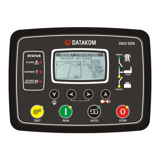
DKG-509 User Manual
DESCRIPTION
The controller is a comprehensive AMF unit for
single genset standby or dual genset mutual standby
operations.
The unit is available with MPU or CANBUS versions.
The CANBUS version connects to ECU controlled
electronic engines providing engine control,
protection and instrumentation without extra senders.
The ECU alarms are displayed in text.
The unit has an optional internal GSM modem
module and is able to initiate modem calls and send
SMS messages in fault conditions through either
internal or external modems.
The unit provides a comprehensive set of digitally
adjustable timers, threshold levels, input and output
configurations, operating sequences and engine
types. All programs may be modified via front panel
pushbuttons, and do not require an external unit.
Last 100 faults are stored in the event log file. The
event log includes not only the date-time information,
but also a comprehensive list of measured genset
parameters at the time that the fault has occurred.
The WINDOWS based RAINBOW program allows
remote monitoring and control.
The unit supports MODBUS protocol enabling
communication with PLCs and building management
systems. The MODBUS protocol is also supported
through GSM and PSTN modems.
The unit offers multiple language support.
DKG-509 AUTOMATIC
MAINS FAILURE UNIT
CANBUS AND MPU VERSIONS
True RMS measurements
ECU connection through J1939 CAN option
J1939 ECU warnings displayed as text
MPU input option
Internal GSM modem option
Dual genset mutual standby operation
Event logging with time stamp and
measurements
Battery backed-up real time clock
Built in daily / weekly / monthly exerciser
Weekly operation schedule programs
Field adjustable parameters
RS-232 serial port
Optional RS-485 serial port
Free MS-Windows Remote monitoring SW
GSM and PSTN modem support
GSM SMS message sending on fault
MODBUS communications
Multiple language support
Customer logo display capability
10ADC relay outputs
Configurable analogue inputs: 4
Configurable digital inputs: 7
Configurable relay outputs: 2
Total relay outputs: 6
I/O expansion capability
Plug-in connection system
V-29
(23.08.2013)
FEATURES
Advertisement
Table of Contents

Subscribe to Our Youtube Channel
Related Manuals for Datakom DKG-509


Summary of Contents for Datakom DKG-509
- Page 1 DKG-509 User Manual V-29 (23.08.2013) DKG-509 AUTOMATIC MAINS FAILURE UNIT CANBUS AND MPU VERSIONS DESCRIPTION FEATURES The controller is a comprehensive AMF unit for True RMS measurements single genset standby or dual genset mutual standby ECU connection through J1939 CAN option operations.
-
Page 2: Table Of Contents
DKG-509 User Manual V-29 (23.08.2013) TABLE OF CONTENTS Section 1. INSTALLATION 1.1. Introduction to the Control Panel 1.2. Mounting the Unit 1.3. Wiring the Unit 2. INPUTS AND OUTPUTS 3. DISPLAYS 3.1. Led Displays 3.2. Language Selection 3.3. Digital Displays 4. -
Page 3: Installation
DKG-509 User Manual V-29 (23.08.2013) 1. INSTALLATION 1.1 Introduction to the Control Panel The unit is a control and protection panel used in gensets. It shows the measured values on its displays. The unit is designed to provide user friendliness for both the installer and the user. -
Page 4: Mounting The Unit
DKG-509 User Manual V-29 (23.08.2013) 1.2 Mounting the Unit The unit is designed for panel mounting. The user should not be able to access parts of the unit other than the front panel. Mount the unit on a flat, vertical surface. Before mounting, remove the mounting brackets and connectors from the unit, then pass the unit through the mounting opening. -
Page 5: Inputs And Outputs
DKG-509 User Manual V-29 (23.08.2013) 2. INPUTS AND OUTPUTS RS-232 SERIAL PORT: This connector provides serial data input and output for various purposes like remote monitoring and remote programming. EXTENSION CONNECTOR: This connector is intended for the connection to output extension modules. - Page 6 DKG-509 User Manual V-29 (23.08.2013) Term Function Technical data Description Connect the charge alternator’s D+ terminal to CHARGE Input and output this terminal. This terminal will supply the excitation current and measure the voltage of the charge alternator. RELAY-2 (HORN RELAY)
-
Page 7: Displays
DKG-509 User Manual V-29 (23.08.2013) 3. DISPLAYS 3.1 Led Displays The unit has 12 LEDs, divided in 3 groups: -Group_1: Operating mode: This group indicates the genset function. -Group_2: Mimic diagram: This group indicates the current status of the mains and genset voltages and contactors. -
Page 8: Language Selection
DKG-509 User Manual V-29 (23.08.2013) 3.2 Language Selection The unit is able to display information in 3 or 4 languages, following versions. Language selection is made through program parameter CONTROLLER CONFIGURATION > LANGUAGE SELECTION. Below selections are available in the standard version:... - Page 9 DKG-509 User Manual V-29 (23.08.2013) Screen Description Contents Mains parameters Genset status (phase to neutral) Mains Volts L1, Mains Frequency Mains Volts L2 , Battery Voltage Mains Volts L3, Coolant Temperature Mains parameters Genset status (phase to phase) Mains Volts L1-L2,...
- Page 10 DKG-509 User Manual V-29 (23.08.2013) Screen Description Contents CANBUS Measurements Percent Torque 1 / 6 Percent Load Fuel Pressure CANBUS Measurements Fuel Rate 2 / 6 Average Fuel Economy Total Engine Hours CANBUS Measurements Air Pressure 3 / 6 Ambient Air Temperature...
-
Page 11: Alarms And Warnings
DKG-509 User Manual V-29 (23.08.2013) 4. ALARMS AND WARNINGS Alarms indicate an abnormal situation in the generating set are divided into 3 priority levels: 1- ALARMS: These are the most important fault conditions and cause: The ALARM led to be on steadily,... - Page 12 DKG-509 User Manual V-29 (23.08.2013) LOW OIL PRESSURE: Set if a signal is detected at the Low Oil Pressure Switch input or the oil pressure value measured from the sender is below the programmed limit. Warning and alarm limits are separately programmable for the oil pressure sender input.
-
Page 13: Modes Of Operation
DKG-509 User Manual V-29 (23.08.2013) 5. MODES OF OPERATION The modes of operation are selected by pushing the front panel keys. Changing the operation mode while the genset is running will result into a behavior suitable for the new operating mode. For example, if the LOAD TEST mode is selected when genset is running at TEST mode, then the genset will take the load. -
Page 14: Other Features
DKG-509 User Manual V-29 (23.08.2013) 6. OTHER FEATURES 6.1 Remote Start Operation The unit offers the possibility of REMOTE START mode of operation. Any digital input may be assigned as Remote Start Input using Input Function Select program parameters. The REMOTE START signal may be a NO or NC contact, switching to either battery positive or battery negative. -
Page 15: Engine Heating Operation
DKG-509 User Manual V-29 (23.08.2013) 6.3 Engine Heating Operation Especially on engines without a body heater, or with a failing one, it may be desired that the genset should not take the load before reaching a suitable temperature. The unit offers 2 different ways of engine heating. -
Page 16: Fuel Pump Control
DKG-509 User Manual V-29 (23.08.2013) 6.6 Fuel Pump Control The unit is able to provide a relay output in order to drive the fuel pump motor. The fuel pump is used in order to transfer fuel from the large capacity main tank (if exists) to the genset daily tank which is generally integrated in the chassis and has a limited capacity. -
Page 17: Delayed Mains Simulation, Battery Charging
DKG-509 User Manual V-29 (23.08.2013) 6.8 Delayed Mains Simulation, Battery Charging The Delayed Mains Simulation feature is used in battery backed up telecom systems where batteries are able to supply the load during a certain period. The genset is requested to run only when battery voltage drops below the critical level. -
Page 18: Dual Genset Mutual Standby Operation
If the priority signal is not applied, then the unit will become the slave one and the other genset will start. Please contact DATAKOM for a complete application manual. - 18 -... -
Page 19: Service Request Display
DKG-509 User Manual V-29 (23.08.2013) 6.10 Service Request Display This led is designed to help the periodic maintenance of the genset to be made consistently. The periodic maintenance is basically carried out after a given engine hours (for example 200 hours), but even if this amount of engine hours is not fulfilled, it is performed after a given time limit (for example 12 months). -
Page 20: Engine Hours Meter
PC connection will not work. Advised modems are DATAKOM types which are powered up from the same DC battery voltage than the unit. Most of other desktop modems with standard AT commands are also usable, but it is the user’s responsibility to provide an uninterrupted AC supply source to the modem. -
Page 21: Sms Message Sending
GSM SMS messages. Any new upcoming alarm will result in a new GSM SMS message. The new message will indicate all existing alarms, even masked ones. The necessary GSM modem cable will be supplied by DATAKOM. This is the same cable as PSTN (land) modems. -
Page 22: Remote Monitoring And Programming
FLEXY USB 1.1 TO SERIAL ADAPTER (PRODUCT CODE BF-810) CASECOM USB TO SERIAL CONVERTER (MODEL: RS-01) The necessary PC connection cable will be supplied by DATAKOM. The cable length should not be over 3 meters. 6.17 External Control of the Unit The unit offers total external control through programmable digital inputs. - Page 23 DKG-509 User Manual V-29 (23.08.2013) 6.18 Exerciser The unit offers automatic exerciser operation. The exercise operation may be done on a daily, weekly or monthly basis. The start day and time of the exercise is programmable as well as its duration. The exercise may be done with or without load following programming.
-
Page 24: Resuming To Factory Set Parameters
DKG-509 User Manual V-29 (23.08.2013) 6.19. Resuming to factory set parameters In order to resume to the factory set parameter values: -hold pressed the OFF, LAMP TEST and ALARM MUTE buttons for 5 seconds, -“RETURN TO FACTORY SET” will be displayed -immediately press and hold pressed the ALARM MUTE button for 5 seconds -factory set values will be reprogrammed to the parameter memory. -
Page 25: Fuel Theft / Fuelling Messages
DKG-509 User Manual V-29 (23.08.2013) 6.22. Fuel Theft / Fuelling Messages The unit is able to send SMS messages in fuel theft or fuelling conditions. These SMS messages are sent without creating visible fault condition. These features are enabled by setting the program parameter Engine Parameters > Fuel Consumption / Hour to a value other than 0%. -
Page 26: Engine Control Mode
DKG-509 User Manual V-29 (23.08.2013) 6.25. Engine Control Mode In engine control mode, the unit is supposed to control an engine without alternator. The engine control mode is activated by a program parameter in the Controller Configuration group. When the Engine Control Mode is activated: -the unit will not display genset AC parameters (volts, amps, kW and pf). - Page 27 DKG-509 User Manual V-29 (23.08.2013) 6.27. Single Phase Operation If the unit is used in a single phase electrical network, it is advised t set the Single Phase Enable program parameter in CONTROLLER CONFIGURATION group to 1. When Single Phase Enable is set to 1, then the unit will measure electrical parameters only on phases L1 of genset and mains.
-
Page 28: J1939 Engine Monitoring And Control Port
Engine Type parameter should be set accordingly. The list of available engines is given at the programming section. Please contact DATAKOM for the most current list of engines. If the J1939 port is enabled then the oil pressure, coolant temperature and the engine rpm information are picked up from the ECU unit. - Page 29 DKG-509 User Manual V-29 (23.08.2013) Below is a basic list of fault conditions (x denotes any FMI) DESCRIPTION Fuel filter restriction Fuel pressure sensor fail Low oil level High oil level Oil level sensor fail Low oil pressure Oil pressure sensor fail...
- Page 30 DKG-509 User Manual V-29 (23.08.2013) Below is a basic list of FMI codes. Please be aware that these codes may differ slightly depending on the engine brand and model. DESCRIPTION Value too high” Valid data, but above the normal working range “Value too low”...
-
Page 31: Modbus Communication
Detailed description about the MODBUS protocol is found in the document “Modicon Modbus Protocol Reference Guide”. The web address is: www.modbus.org/docs/PI_MBUS_300.pdf Below is a limited shortlist of readable registers. For the detailed Modbus Application Manual and a complete list of registers please contact DATAKOM. ADDRESS DATA... -
Page 32: Weekly Operation Schedule
DKG-509 User Manual V-29 (23.08.2013) 9. WEEKLY OPERATION SCHEDULE In most applications, the genset is requested to operate only in working hours. Thanks to the weekly program feature unwanted operation of the genset may be prohibited. The unit has one programmable turn-on/turn-off time pairs for each day of week. These programmable parameters allow the genset to operate automatically only in allowed time limits. -
Page 33: Event Logging
DKG-509 User Manual V-29 (23.08.2013) 10. EVENT LOGGING The unit keeps record of the last 100 events in order to supply information for the service personal. The genset status information and a comprehensive set of measured values are stored within the event memory. -
Page 34: Statistical Counters
DKG-509 User Manual V-29 (23.08.2013) 11. STATISTICAL COUNTERS The unit provides a set of non resettable incremental counters for statistical purposes. The counters consist on: -total engine hours -total genset KWh -engine hours to service -time to service -total engine cranks -total genset runs These counters are kept in a non-volatile memory and are not affected from power failures. -
Page 35: Programming
The password level-1 allows access to field adjusted parameters. The level-2 allows access to factory setup. The password level-3 is reserved to Datakom and allows access to calibration parameters. The password level-1 is factory set to ‘1234’ and the password level-2 is factory set to ‘9876’. - Page 36 DKG-509 User Manual V-29 (23.08.2013) Program Group: Controller Configuration Parameter Definition, Unit Factory Description (Password Level) This parameter is used to set LCD contrast. Adjust for (1) LCD Contrast the best viewing angle. 0: English language selected. 1: Turkish language selected. This language may...
- Page 37 1: temperature display in degrees F Delayed Simulate Mains Operation: max genset running time after Simulate Mains signal disappears. (2) Flashing Relay Timer Dual Genset Systems: flashing relay toggle timer. hours Please contact DATAKOM for dual genset mutual stanby operation. - 37 -...
- Page 38 DKG-509 User Manual V-29 (23.08.2013) Program Group: Controller Configuration (continued) Parameter Definition, Unit Factory Description (Password Level) This parameter trims precisely the real time clock circuit. Values from 0 to 63 speed up the clock with (1) Real Time Clock Adjust 0.25sec/day steps.
- Page 39 DKG-509 User Manual V-29 (23.08.2013) Program Group: Electrical Parameters Parameter Definition, Unit Facto Description (Password Level) ry Set This is the rated value of current transformers. (2) Current Transformer All transformers must have the same rating. Ratio The secondary of the transformer will be 5 Amps.
- Page 40 DKG-509 User Manual V-29 (23.08.2013) Program Group: Electrical Parameters (continued) Parameter Definition, Factor Unit Description (Password Level) y Set (2) Low Battery Voltage If the battery voltage falls below this limit, this will Warning generate a LOW BATTERY warning. (2) High Battery Voltage If the battery voltage goes over this limit, this will 31.0...
- Page 41 DKG-509 User Manual V-29 (23.08.2013) Program Group: Electrical Parameters (continued) Parameter Definition, Factory Unit Description (Password Level) When secondary volt/freq limits are active: If the current goes above this limit, during the period defined in Overload Timeout then a Overcurrent...
- Page 42 DKG-509 User Manual V-29 (23.08.2013) Program Group: Engine Parameters Parameter Definition, Factory Unit Description (Password Level) (2) Low Frequency If the genset frequency goes under this limit, a GENSET Shutdown LOW SPEED alarm is generated and the engine stops. If the genset frequency goes under this limit, a GENSET (1) Low Frequency Warning LOW SPEED warning is generated.
- Page 43 DKG-509 User Manual V-29 (23.08.2013) Program Group: Engine Parameters (continued) Parameter Definition, Unit Factory Description (Password Level) This is the maximum start period. Starting will be (2) Crank Timer automatically cancelled if the genset fires before the timer. (2) Wait Between Starts This is the waiting period between two start attempts.
- Page 44 DKG-509 User Manual V-29 (23.08.2013) Program Group: Engine Parameters (continued) Parameter Definition, Unit Factory Description (Password Level) When the genset frequency reaches this limit, the (3) Crank Cut Frequency 10.0 engine is supposed running and the crank output will release.
- Page 45 DKG-509 User Manual V-29 (23.08.2013) Program Group: Engine Parameters (continued) Parameter Definition, Unit Factory Description (Password Level) When secondary volt/freq limits are active: (2) 2 Low Frequency If the genset frequency goes under this limit, a GENSET LOW SPEED alarm is generated and the Shutdown engine stops.
- Page 46 DKG-509 User Manual V-29 (23.08.2013) Below parameters are applicable to J1939 enabled versions only. Program Group: Engine Parameters (continued) Parameter Definition, Unit Factory Description (Password Level) 0: The J1939 port is inoperative. 1: The analog measurements (oil, temp, rpm) are (2) J1939 Enable picked_up from the ECU.
- Page 47 DKG-509 User Manual V-29 (23.08.2013) Program Group: Adjust Date and Time (password level-2) Parameter Definition Unit Factory Description Date 01-31 Current day of the month. Month 01-12 Current month. Year 00-99 Last two digits of the current year. Hours 00-23 Current hour of the day.
- Page 48 DKG-509 User Manual V-29 (23.08.2013) Program Group: Sender Characteristics (password level-2) Parameter Definition Unit Factory Description Oil Pressure Sender point 1, ohm value Oil Pressure Sender Ohms -1 Oil Pressure Sender point 1, bar value Oil Pressure Value -1 Oil Pressure Sender point 2, ohm value...
- Page 49 DKG-509 User Manual V-29 (23.08.2013) Program Group: Sender Characteristics (password level-2) Parameter Definition Unit Factory Description Fuel Level Sender point 1, ohm value Fuel Level Sender Ohms -1 Fuel Level Sender point 1, % value Fuel Level Value -1 Fuel Level Sender point 2, ohm value...
- Page 50 DKG-509 User Manual V-29 (23.08.2013) Program Group: Input Configuration (Low Oil Pressure Switch) (password level-2) Parameter Definition Unit Fac.Set Description 0: Shutdown (the engine stops immediately) 1: Load Dump (the engine stops after cooldown) Action 2: Warning (the horn relay operates)
- Page 51 DKG-509 User Manual V-29 (23.08.2013) Program Group: Input Configuration (Coolant Level Switch) (password level-2) Parameter Definition Unit Fac.Set Description 0: Shutdown (the engine stops immediately) 1: Load Dump (the engine stops after cooldown) Action 2: Warning (the horn relay operates)
- Page 52 DKG-509 User Manual V-29 (23.08.2013) Program Group: Input Configuration (Emergency Stop) (password level-2) Parameter Definition Unit Fac.Set Description 0: Shutdown (the engine stops immediately) 1: Load Dump (the engine stops after cooldown) Action 2: Warning (the horn relay operates) 3: No operation...
- Page 53 DKG-509 User Manual V-29 (23.08.2013) Program Group: Input Configuration (Spare-2 Input) (password level-2) Parameter Definition Unit Fac.Set Description 0: Shutdown (the engine stops immediately) 1: Load Dump (the engine stops after cooldown) Action 2: Warning (the horn relay operates) 3: No operation...
- Page 54 DKG-509 User Manual V-29 (23.08.2013) The parameters below define the functions of relay outputs. The unit has 6 relay outputs. The fixed function relays are Fuel, Start, Mains Contactor and Generator Contactor. RELAY-1 and RELAY- 2 have programmable functions, selected from a list.
- Page 55 DKG-509 User Manual V-29 (23.08.2013) The function of a programmable relay output may be selected from the below list. Fuel Oil switch alarm Oil switch warning Alarm Temp switch alarm Temp switch warn. Start Coolant Level switch Coolant Level switch...
- Page 56 DKG-509 User Manual V-29 (23.08.2013) The parameters below define the functions of digital inputs, selected from a list. Functions from 12 to 23 activate also the related operating sequence. The related input configuration parameters apply for each input, thus any signal can be programmed for NO or NC contact, closing to BAT+ or BAT-.
- Page 57 DKG-509 User Manual V-29 (23.08.2013) Program Group: Site Id (password level-2) Parameter Definition Factory Set Description This is the site Id string sent at the beginning of an DATAKOM SITE SMS message for the identification of the genset Site Id String sending the SMS message.
- Page 58 DKG-509 User Manual V-29 (23.08.2013) 14. TROUBLESHOOTING The genset operates while AC mains are OK or continues to operate after AC mains are OK: -Check engine body grounding. -AC mains voltages may be outside programmed limits, measure the phase voltages.
- Page 59 DKG-509 User Manual V-29 (23.08.2013) When the AC mains fails, the engine starts to run but the unit gives START FAIL alarm and then the engine stops: -The generator phase voltages are not connected to the unit. Measure the AC voltage between terminals GEN L1-L2-L3 and Generator Neutral at the rear of the unit while the engine is running.
- Page 60 DKG-509 User Manual V-29 (23.08.2013) 15. DECLARATION OF CONFORMITY The unit conforms to the EU directives -2006/95/EC (low voltage) -2004/108/EC (electro-magnetic compatibility) Norms of reference: EN 61010 (safety requirements) EN 61326 (EMC requirements) The CE mark indicates that this product complies with the European requirements for safety, health environmental and customer protection.
- Page 61 DKG-509 User Manual V-29 (23.08.2013) 16. TECHNICAL SPECIFICATIONS Alternator voltage: 0 to 300 V-AC Phase to Neutral (0 to 520 V-AC Phase to Phase) Alternator frequency: 0-100 Hz. Mains voltage: 0 to 300 V-AC Phase to Neutral (0 to 520 V-AC Phase to Phase) Mains frequency: 0-100 Hz.
- Page 62 DKG-509 User Manual V-29 (23.08.2013) 17. CONNECTION DIAGRAMS - 62 -...
- Page 63 DKG-509 User Manual V-29 (23.08.2013) DATAKOM Electronics Ltd. Tel: +90-216-466 84 60 Fax: +90-216-364 65 65 e-mail: datakom@datakom.com.tr http: www.datakom.com.tr - 63 -...
Need help?
Do you have a question about the DKG-509 and is the answer not in the manual?
Questions and answers