Table of Contents
Advertisement
DKG-255 User Manual
DESCRIPTION
The DKG-255 is a microprocessor controlled digital
speed control unit designed to control the engine
speed with fast and accurate response to load
changes.
The DKG-255 connects to a forward acting
proportional electric actuator and a magnetic speed
sensor. It is also capable of picking-up the speed
signal from the alternator voltage, removing the need
for a MPU unit. It controls a wide variety of engines
in constant speed (isochronous) or droop modes.
The DKG-255 offers programmable parameters to
adjust IDLE and RATED speed settings. The IDLE
speed mode is selected with an external switch.
The automatic PID speed regulation function controls
the dynamic performance of the unit and allows
stable operation with most engine types.
The unit is able to adjust automatically its PID
settings, simplifying the programming process and
improving the dynamic response quality.
An external speed trim potentiometer may be
connected to the unit to adjust the engine speed
from a remote location.
The auxiliary speed adjustment input allows voltage
controlled speed trimming for synchronizing and load
sharing applications.
If an adequate speed signal is not supplied to the
unit, the speed signal monitoring circuit will detect
this and shut-off the actuator output in order to
prevent any damage.
The unit is capable to deliver actuator currents as
high as 10 Amps. However, the output current
limiting circuit will protect the unit against output
short circuit or overload.
Protection against reverse battery connection and
transient voltages are provided.
DKG-255
DIGITAL SPEED
CONTROLLER
FEATURES
•
Automatic PID Setup functionality
•
Microprocessor controlled
•
12 and 24V operation
•
Capable of governing various engines
•
Forward acting actuator output
•
Fast and accurate response
•
Starting fuel adjustment
•
Speed ramp adjustment
•
Adjustable rated and idle speeds
•
Isochronous and droop operation
•
Gain and stability adjustments
•
External speed adjustment capability
•
Synchronizing and load sharing input
•
Switch mode output circuit
•
10 Amps continuous current output
•
Speed sensor failure detection
•
Battery reverse voltage protection
•
Output short circuit protection
•
Rugged design
•
Enamel protected electronic circuit
•
Small dimensions (130x110x27mm)
•
Low cost
Firmware V-1.0
Advertisement
Table of Contents

Subscribe to Our Youtube Channel
Related Manuals for Datakom DKG-255


Summary of Contents for Datakom DKG-255
- Page 1 DKG-255 User Manual Firmware V-1.0 DKG-255 DIGITAL SPEED CONTROLLER DESCRIPTION FEATURES The DKG-255 is a microprocessor controlled digital • Automatic PID Setup functionality speed control unit designed to control the engine • speed with fast and accurate response to load Microprocessor controlled changes.
- Page 2 DKG-255 unit. Follow carefully advices given in the document. These are often good practices for the installation of digital speed control unit which reduce future issues. For all technical queries please contact Datakom at below e-mail address: technical.support@datakom.com.tr QUERRIES...
- Page 3 DKG-255 User Manual Firmware V-1.0 REVISION HISTORY REVISION DATE AUTHOR DESCRIPTION 10.04.2019 First edition, firmware version 1.0 TERMINOLOGY CAUTION: Potential risk of injury or death. WARNING: Potential risk of malfunction or material damage. ATTENTION: Useful hints for the understanding of device operation.
- Page 4 DKG-255 User Manual Firmware V-1.0 SAFETY NOTICE Failure to follow below instructions will result in death or serious injury Electrical equipment should be installed only by qualified specialist. No responsibility is assured by the manufacturer or any of its subsidiaries for any consequences resulting from the non-compliance to these instructions.
-
Page 5: Table Of Contents
DKG-255 User Manual Firmware V-1.0 TABLE OF CONTENTS 1. INSTALLATION INSTRUCTIONS 1.1 INTRODUCTION TO THE CONTROL UNIT 1.2 MOUNTING THE UNIT 1.3 WIRING THE UNIT 2. TERMINAL DESCRIPTIONS 3. TECHNICAL SPECIFICATIONS 4. DESCRIPTION OF CONTROLS 4.1. FRONT PANEL FUNCTIONALITY 4.2. PUSHBUTTON FUNCTIONS 4.3. -
Page 6: Installation Instructions
1. INSTALLATION INSTRUCTIONS 1.1 Introduction to the Control Unit The DKG-255 is a microprocessor controlled governor control unit designed to control the engine speed with fast and accurate response to load changes. The DKG-255 connects to a forward acting proportional electric actuator and a magnetic speed sensor. -
Page 7: Wiring The Unit
DKG-255 User Manual Firmware V-1.0 1.3 Wiring the Unit Cables of section 1.5mm² or higher should be used for battery and actuator connections (terminals A-B- C-D). The section needs to be increased with long cable lengths. THE UNIT IS NOT FUSED. Use external fuse for battery positive (terminal C) Install the fuse as nearly as possible to the unit. -
Page 8: Terminal Descriptions
DKG-255 User Manual Firmware V-1.0 2. TERMINAL DESCRIPTIONS Term Function Technical data Description Actuator - Output, 10A max These outputs supply energy to the electric actuator. The output voltage will Actuator + increase in order to supply more fuel to the engine. -
Page 9: Technical Specifications
DKG-255 User Manual Firmware V-1.0 3. TECHNICAL SPECIFICATIONS DC Supply Range: 10.0 to 33.0 V-DC Current consumption: 100mA max (actuator not connected) Speed input range: 40 Hz to 8000 Hz. Speed signal amplitude: 1.5 to 300 VAC-RMS Speed signal input impedance: 2 M- ohms... -
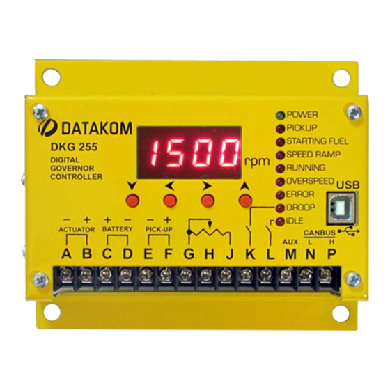
Page 10: Description Of Controls
DKG-255 User Manual Firmware V-1.0 4. DESCRIPTION OF CONTROLS 4.1. FRONT PANEL FUNCTIONALITY Power Led Led display Status Leds Pushbuttons USB Device COLOR FUNCTION Power green Led turns on when battery voltage is supplied to terminals C-D. Pickup Led turns on when speed signal is available at terminals E-F Led turns on when the engine rpm is above “cranking rpm”... -
Page 11: Pushbutton Functions
DKG-255 User Manual Firmware V-1.0 4.2. PUSHBUTTON FUNCTIONS BUTTON FUNCTION Switches the display to the parameter name of the value displayed on led screen. PROGRAMMING MODE: Save the set value and select next parameter. PROGRAMMING MODE: Return to main menu of parameters. -
Page 12: Led Display Organization
DKG-255 User Manual Firmware V-1.0 4.3. LED DISPLAY ORGANIZATION The unit is a control and protection device used in diesel engines. It shows measured values on its display. The unit is designed to provide user friendliness for both the installer and the user. - Page 13 DKG-255 User Manual Firmware V-1.0 Navigate to next measurement Measured parameter Frequency Navigate to next measurement Measured parameter Battery Voltage - 13 -...
- Page 14 DKG-255 User Manual Firmware V-1.0 Navigate to next measurement Measured parameter Minimum Engine rpm Navigate to next measurement Measured parameter Maximum Engine rpm - 14 -...
-
Page 15: Protection And Alarms
DKG-255 User Manual Firmware V-1.0 5. PROTECTIONS AND ALARMS The unit continuously monitors abnormal conditions during operation. Programmable alarm limits are provided for every measured value. If any fault condition occurs, the related error led turns on and an alarm code is displayed. -
Page 16: Programming
DKG-255 User Manual Firmware V-1.0 6. PROGRAMMING The program mode is used to adjust parameters. To enter the program mode, hold pressed buttons for 5 seconds. When the program mode is entered, the display will show “PGM”. The program mode will not affect the operation of the unit. Thus, programs may be modified anytime, even while the engine is running. - Page 17 DKG-255 User Manual Firmware V-1.0 Navigation between program parameters is performed via the button. Press button to enter inside the selected parameter. Parameter value may be increased and decreased with buttons. When a program parameter is modified, press button to save in memory.
-
Page 18: Program Parameter List
DKG-255 User Manual Firmware V-1.0 7. PROGRAM PARAMETER LIST Factory Parameter Definition Unit Description This parameter defines the nominal P_01 Nominal Speed 1000 2000 1500 (target) speed of the engine. This parameter defines the idle speed P_02 Idle Speed 1500 of the engine when idle input is active. - Page 19 DKG-255 User Manual Firmware V-1.0 7. PROGRAM PARAMETER LIST (continued) Factory Parameter Definition Unit Description This is the parameter to enable auto PID setup operation. P_22 PID Auto Setup 0: PID Auto Setup disabled 1: PID Auto Setup enabled P_23 Actuator Maximum...
-
Page 20: Operation Of The Unit
DKG-255 User Manual Firmware V-1.0 8. OPERATION OF THE UNIT The unit is designed to operate from a DC supply of 12 or 24 volts, which is usually the engine starter battery. The battery is connected to terminals C and D. A reverse polarity protection is provided. -
Page 21: Other Features
DKG-255 User Manual Firmware V-1.0 9. OTHER FEATURES 9.1. Isochronous and Droop Operation The typical operation mode of the unit is isochronous (constant speed). However, a droop operation may be required for load sharing purposes on genset engines. In droop operation, the engine speed will decrease slightly with load increase. The load information is picked up from the actuator current, which increases together with the load. -
Page 22: Starting Fuel Adjustment
The unit in BOOT LOADER mode will wait for a PC connection through its USB port. When the unit establishes USB connection, the device will be automatically recognized by the PC and will appear as a Device with Removable Storage. After deleting firmware file, copy the new firmware provided by Datakom into this disk. -
Page 23: Connection Diagram
DKG-255 User Manual Firmware V-1.0 10. CONNECTION DIAGRAM - 23 -... -
Page 24: Declaration Of Conformity
ROHS directive. However, Datakom is not using any ROHS uncompliant electronic components in the production. Only the solder contains lead. The switching to unleaded soldering is in progress. - 24 -... -
Page 25: Troubleshooting Guide
DKG-255 User Manual Firmware V-1.0 15. TROUBLESHOOTING GUIDE Below is a basic list of most often encountered troubles. More detailed investigation may be required in some cases. The actuator is inoperative: 1) Measure the DC-supply voltage between terminals C(+) and D(-) of the unit. You should read... - Page 26 DKG-255 User Manual Firmware V-1.0 Engine overspeeds: Do not crank again. 1) With the unit powered-up, if the actuator opens fully: a) Disconnect wiring at terminals E and F. If the actuator closes then the speed signal is faulty, probably due to electrical noises.
Need help?
Do you have a question about the DKG-255 and is the answer not in the manual?
Questions and answers