Table of Contents
Advertisement
DKG-329 User Manual
WITH UNINTERRUPTED TRANSFER AND MULTIPLE GENSET SUPPORT
DESCRIPTION
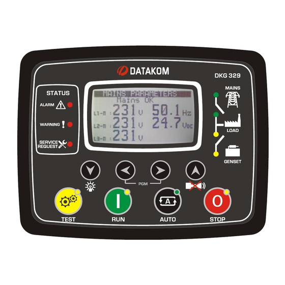
The DKG-329 is microprocessor controlled unit
designed to monitor 3-phase mains voltages, send
remote start command to generating sets and
control the changeover of generator and mains
contactors.
The unit offers an internal synchroscope for
uninterrupted transfer in both directions. The
number of gensets to run before transfer is
selectable, allowing multiple genset support.
If a fault condition occurs, the unit disables the
remote starting automatically and indicates the
failure with the corresponding led lamp and text.
The unit provides a comprehensive set of digitally
adjustable program parameters. The unauthorized
access to program parameters is prevented by a 3
level password system. All programs may be
modified via front panel pushbuttons and do not
require any external unit.
Last 100 faults are stored in the event log file. The
event log includes not only the date-time
information, but also a comprehensive list of
measured parameters at the time that the fault has
occurred.
The WINDOWS based RAINBOW program
allows remote monitoring and control.
The unit supports MODBUS protocol enabling
communication with PLCs and building
management systems. The MODBUS protocol is
also supported through GSM and PSTN
modems.
DKG-329 AUTOMATIC
TRANSFER SWITCH
CONTROLLER
FEATURES
True RMS measurements
Synchroscope & check synch
No break transfer& no break load test
Automatic contactor control
Multiple genset system support
Load shedding, dummy load
Event logging with time stamp and measurements
Battery backed-up real time clock
Built in daily / weekly / monthly exerciser
Weekly operation schedule programs
Field adjustable parameters
RS-232 serial port
Free MS-Windows Remote monitoring SW
GSM and PSTN modem support
GSM SMS message sending on fault
MODBUS communications
Multiple language support
Customer logo display capability
16 Amp contactor outputs
1 Amp DC semiconductor control outputs
Configurable digital inputs: 7
Configurable digital outputs: 3
Total digital outputs: 6
I/O expansion capability
Plug-in connection system
Sealed front panel
V-12
(09.10.2012)
Advertisement
Table of Contents

Related Manuals for Datakom DKG-329


Summary of Contents for Datakom DKG-329
- Page 1 WITH UNINTERRUPTED TRANSFER AND MULTIPLE GENSET SUPPORT DESCRIPTION FEATURES True RMS measurements The DKG-329 is microprocessor controlled unit designed to monitor 3-phase mains voltages, send Synchroscope & check synch remote start command to generating sets and No break transfer& no break load test...
-
Page 2: Table Of Contents
DKG-329 User Manual V-12 (09.10.2012) TABLE OF CONTENTS Section 1. INSTALLATION 1.1. Introduction to the Control Panel 1.2. Mounting the Unit 1.3. Wiring the Unit 2. INPUTS AND OUTPUTS 3. DISPLAYS 3.1. Led Displays 3.2. Language Selection 3.3. Digital Display 4. -
Page 3: Installation
DKG-329 User Manual V-12 (09.10.2012) 1. INSTALLATION 1.1 Introduction to the Control Panel The unit is a control and protection panel designed to monitor the 3-phase mains voltages, send remote start command to the generating set and make changeover of both generator and mains contactors. The genset is It shows the measured values on its display. -
Page 4: Wiring The Unit
DKG-329 User Manual V-12 (09.10.2012) 1.3 Wiring the Unit WARNING: THE UNIT IS NOT FUSED. Use external fuses for Mains phases: L1,L2,L3, Generator phase: L1,L2,L3, Battery positive: BAT(+). Install the fuses as nearly as possible to the unit in a place easily accessible for the user. -
Page 5: Inputs And Outputs
DKG-329 User Manual V-12 (09.10.2012) 2. INPUTS AND OUTPUTS RS-232 SERIAL PORT: This connector provides serial data input and output for various purposes like remote monitoring and remote programming. EXTENSION CONNECTOR: This connector is intended for the connection to output extension modules. - Page 6 DKG-329 User Manual V-12 (09.10.2012) Term Function Technical data Description RELAY-1 Output 1A/28VDC This relay programmable function, selectable from a list. RELAY-2 Output 1A/28VDC This relay programmable function, selectable from a list. HORN RELAY OUTPUT Output 1A/28VDC This relay controls the horn...
-
Page 7: Displays
DKG-329 User Manual V-12 (09.10.2012) 3. DISPLAYS 3.1 Led Displays The unit has 12 LEDs, divided in 3 groups: -Group_1: Operating mode: This group indicates the genset function. -Group_2: Mimic diagram: This group indicates the current status of the mains and genset voltages and contactors. -
Page 8: Language Selection
DKG-329 User Manual V-12 (09.10.2012) 3.2 Language Selection The unit is able to display information in 3 languages. Language selection is made through program parameter CONTROLLER CONFIGURATION > LANGUAGE SELECTION. Below selections are available: 0: English language 1: Turkish language... - Page 9 DKG-329 User Manual V-12 (09.10.2012) Screen Description Contents Mains parameters Genset status (phase to neutral) Mains Volts L1, Mains Frequency Mains Volts L2 , Battery Voltage Mains Volts L3, Mains parameters Genset status (phase to phase) Mains Volts L1-L2, Mains Frequency...
-
Page 10: Alarms And Warnings
DKG-329 User Manual V-12 (09.10.2012) 4. ALARMS AND WARNINGS Alarms indicate an abnormal situation in the generating set are divided into 3 priority levels: 1- ALARMS: These are the most important fault conditions and cause: The ALARM led to be on steadily,... -
Page 11: Modes Of Operation
DKG-329 User Manual V-12 (09.10.2012) STOP FAIL (warning): Set if the engine has not stopped before the expiration of the Stop Timer. OVERLOAD (load_dump): Set if at least one of the genset phase currents goes over the Overcurrent Limit for Overload Timer. If currents goes below the limit before expiration of the timer then no alarm will be set. -
Page 12: Load Transfer Modes
DKG-329 User Manual V-12 (09.10.2012) 6. LOAD TRANSFER MODES The unit has two ways of transferring the load from genset to mains and vice versa. These modes are: -transfer with interruption. -no break transfer. 6.1 Transfer with Interruption This is the most conventional way of transferring the load between the genset and mains. There will be a power interruption period duration during the transfer. - Page 13 DKG-329 User Manual V-12 (09.10.2012) When a No Break Transfer cycle is initiated, the unit checks all the above criteria to be satisfied as long as the Synchronization Fail Timeout is not expired. Normally with frequencies matching at +/- 2Hz and voltages matching at +/-10 volts an uncontrolled No Break Transfer will be successfull.
-
Page 14: Other Features
DKG-329 User Manual V-12 (09.10.2012) 7. OTHER FEATURES 7.1 Remote Start Operation The unit offers the possibility of REMOTE START mode of operation. Any digital input may be assigned as Remote Start Input using Input Function Select program parameters. The REMOTE START signal may be a NO or NC contact, switching to either battery positive or battery negative. -
Page 15: Delayed Mains Simulation, Battery Charging
DKG-329 User Manual V-12 (09.10.2012) 7.3 Delayed Mains Simulation, Battery Charging The Delayed Mains Simulation feature is used in battery backed up telecom systems where batteries are able to supply the load during a certain period. The genset is requested to run only when battery voltage drops below the critical level. -
Page 16: Service Request Display
DKG-329 User Manual V-12 (09.10.2012) 7.4 Service Request Display This led is designed to help the periodic maintenance of the genset to be made consistently. The periodic maintenance is basically carried out after a given engine hours (for example 200 hours), but even if this amount of engine hours is not fulfilled, it is performed after a given time limit (for example 12 months). -
Page 17: Modem Connection
PC connection will not work. Advised modems are DATAKOM types which are powered up from the same DC battery voltage than the unit. Most of other desktop modems with standard AT commands are also usable, but it is the user’s responsibility to provide an uninterrupted AC supply source to the modem. -
Page 18: Sms Message Sending
GSM SMS messages. Any new upcoming alarm will result in a new GSM SMS message. The new message will indicate all existing alarms, even masked ones. The necessary GSM modem cable will be supplied by DATAKOM. This is the same cable as PSTN (land) modems. -
Page 19: Remote Monitoring And Programming
FLEXY USB 1.1 TO SERIAL ADAPTER (PRODUCT CODE BF-810) CASECOM USB TO SERIAL CONVERTER (MODEL: RS-01) The necessary PC connection cable will be supplied by DATAKOM. 7.11 External Control of the Unit The unit offers total external control through programmable digital inputs. Each digital input may be... -
Page 20: Resuming To Factory Set Parameters
DKG-329 User Manual V-12 (09.10.2012) 7.12 Exerciser The unit offers automatic exerciser operation. The exercise operation may be done on a daily, weekly or monthly basis. The start day and time of the exercise is programmable as well as its duration. The exercise may be done with or without load following programming. -
Page 21: Load Shedding / Dummy Load
DKG-329 User Manual V-12 (09.10.2012) 7.14. Load Shedding / Dummy Load The load shedding feature consists on the disconnection of the least crucial loads when the genset power approaches to its limits. These loads will be supplied again when the genset power falls below the programmed limit. -
Page 22: Modbus Communication
Detailed description about the MODBUS protocol is found in the document “Modicon Modbus Protocol Reference Guide”. The web address is: www.modbus.org/docs/PI_MBUS_300.pdf Below is a limited shortlist of readable registers. For the detailed Modbus Application Manual and a complete list of registers please contact DATAKOM. ADDRESS DATA... -
Page 23: Weekly Operation Schedule
DKG-329 User Manual V-12 (09.10.2012) 9. WEEKLY OPERATION SCHEDULE In most applications, the genset is requested to operate only in working hours. Thanks to the weekly program feature unwanted operation of the genset may be prohibited. The unit has one programmable turn-on/turn-off time pairs for each day of week. These programmable parameters allow the genset to operate automatically only in allowed time limits. -
Page 24: Event Logging
DKG-329 User Manual V-12 (09.10.2012) 10. EVENT LOGGING The unit keeps record of the last 100 events in order to supply information for the service personal. The genset status information and a comprehensive set of measured values are stored within the event memory. -
Page 25: Statistical Counters
DKG-329 User Manual V-12 (09.10.2012) 11. STATISTICAL COUNTERS The unit provides a set of non resettable incremental counters for statistical purposes. The counters consist on: -total engine hours -total genset kWh -engine hours to service -time to service These counters are kept in a non-volatile memory and are not affected from power failures. -
Page 26: Programming
The password level-1 allows access to field adjusted parameters. The level-2 allows access to factory setup. The password level-3 is reserved to Datakom and allows access to calibration parameters. The password level-1 is factory set to ‘1234’ and the password level-2 is factory set to ‘9876’. - Page 27 DKG-329 User Manual V-12 (09.10.2012) Program Group: Controller Configuration Parameter Definition, Unit Factory Description (Password Level) This parameter is used to set LCD contrast. Adjust for (1) LCD Contrast the best viewing angle. 0: English language selected. 1: Turkish language selected. This language may...
- Page 28 DKG-329 User Manual V-12 (09.10.2012) Program Group: Controller Configuration (continued) Parameter Definition, Unit Factory Description (Password Level) This parameter defines the exercise duration and (1) Exercise Duration programmed in 10 minute steps up to 24 hours. 0: Exercise at TEST mode...
- Page 29 DKG-329 User Manual V-12 (09.10.2012) Program Group: Controller Configuration (continued) Parameter Definition, Unit Factory Description (Password Level) This parameter defines minimum activated input (2) Minimum ready input number required to start transfer the load from mains number for transfer to genset.
- Page 30 DKG-329 User Manual V-12 (09.10.2012) Program Group: Electrical Parameters Parameter Definition, Unit Factory Description (Password Level) This is the rated value of current transformers. (2) Current Transformer All transformers must have the same rating. Ratio The secondary of the transformer will be 5 Amps.
- Page 31 DKG-329 User Manual V-12 (09.10.2012) Program Group: Electrical Parameters (continued) Parameter Definition, Factory Unit Description (Password Level) (2) Low Battery Voltage If the battery voltage falls below this limit, this will Warning generate a LOW BATTERY warning. (2) High Battery Voltage If the battery voltage goes over this limit, this will 31.0...
- Page 32 DKG-329 User Manual V-12 (09.10.2012) Program Group: Engine Parameters Parameter Definition, Factory Unit Description (Password Level) (2) Low Frequency If the genset frequency goes under this limit, a GENSET Shutdown LOW SPEED alarm is generated and the engine stops. If the genset frequency goes under this limit, a GENSET (1) Low Frequency Warning LOW SPEED warning is generated.
- Page 33 DKG-329 User Manual V-12 (09.10.2012) Program Group: Weekly Schedule (password level-2) Parameter Definition Unit Factory Description Monday Turn_on 24:00 Monday Turn_off 24:00 Tuesday Turn_on 24:00 Tuesday Turn_off 24:00 Wednesday Turn_on 24:00 Wednesday Turn_off 24:00 Thursday Turn_on 24:00 Please review chapter 9 for a detailed description of weekly programming schedule operation.
- Page 34 DKG-329 User Manual V-12 (09.10.2012) Program Group: Input Configuration (Spare -1 Input) (password level-2) Parameter Definition Unit Fac.Set Description 0: Shutdown (the engine stops immediately) 1: Load Dump (the engine stops after cooldown) Action 2: Warning (the horn relay operates)
- Page 35 DKG-329 User Manual V-12 (09.10.2012) Program Group: Input Configuration (Spare -3 Input) (password level-2) Parameter Definition Unit Fac.Set Description 0: Shutdown (the engine stops immediately) 1: Load Dump (the engine stops after cooldown) Action 2: Warning (the horn relay operates)
- Page 36 DKG-329 User Manual V-12 (09.10.2012) Program Group: Input Configuration (Alarm Mute) (password level-2) Parameter Definition Unit Fac.Set Description 0: Shutdown (the engine stops immediately) 1: Load Dump (the engine stops after cooldown) Action 2: Warning (the horn relay operates) 3: No operation...
- Page 37 DKG-329 User Manual V-12 (09.10.2012) Program Group: Relay Definitions (password level-2) Parameter Definition Unit Fac.Set Description RELAY-1 function selected from list Relay 01 Definition RELAY-2 function selected from list Relay 02 Definition Relay 03 Definition RELAY-3 function (expansion module) selected from list...
- Page 38 DKG-329 User Manual V-12 (09.10.2012) The function of a programmable relay output may be selected from the below list. Remote Start Alarm Gen. Contactor Emerg.Stop alarm Emerg Stop warn. Mains Contactor Spare-1 Alarm Spare-1 warning Spare-2 Alarm Spare-2 warning Shutdown alarm...
- Page 39 DKG-329 User Manual V-12 (09.10.2012) Program Group: Input Function Select (password level-2) Fact. Parameter Definition Description Emergency Stop Input 01 Function Select Spare-1 Input 02 Function Select Input 03 Function Select Spare-2 Spare -3 Input 04 Function Select Fault Reset...
- Page 40 DKG-329 User Manual V-12 (09.10.2012) Program Group: Site Id (password level-2) Parameter Definition Factory Set Description This is the site Id string sent at the beginning of an DATAKOM SITE SMS message for the identification of the genset Site Id String sending the SMS message.
-
Page 41: Troubleshooting
DKG-329 User Manual V-12 (09.10.2012) 14. TROUBLESHOOTING The genset operates while AC mains are OK or continues to operate after AC mains are OK: -Check engine body grounding. -AC mains voltages may be outside programmed limits, measure the phase voltages. -
Page 42: Declaration Of Conformity
DKG-329 User Manual V-12 (09.10.2012) 15. DECLARATION OF CONFORMITY The unit conforms to the EU directives -2006/95/EC (low voltage) -2004/108/EC (electro-magnetic compatibility) Norms of reference: EN 61010 (safety requirements) EN 61326 (EMC requirements) The CE mark indicates that this product complies with the European requirements for safety, health environmental and customer protection. -
Page 43: Connection Diagram
DKG-329 User Manual V-12 (09.10.2012) 17. CONNECTION DIAGRAM DATAKOM Electronics Ltd. Tel: +90-216-466 84 60 Fax: +90-216-364 65 65 e-mail: datakom@datakom.com.tr http: www.datakom.com.tr - 43 -...
Need help?
Do you have a question about the DKG-329 and is the answer not in the manual?
Questions and answers