Table of Contents
Advertisement
Quick Links
DKM-046 User Manual
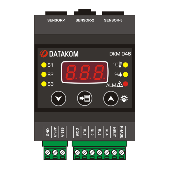
DKM-046
TEMPERATURE &
HUMIDITY
CONTROLLER
DESCRIPTION
DKM-046 is a DIN Rail mounted precision
unit capable of measuring temperature and
humidity in three different locations, provide
protection with 4 relay outputs and serve data
to remote monitoring and control systems.
Sensing modules are separated from the
base unit, connecting with cables. One
sensor comes together with the base unit.
Additional sensors may be purchased
separately.
Two different auxiliary supply versions are
available. The AC model accepts 85 to
305VAC and the DC model accepts 19 to
150VDC.
The module provides data to automation and
BMS systems through its isolated RS-485
Modbus port.
The programming is performed through
pushbuttons on the unit.
Sensor modules incorporate ST-HTS221
polymer dielectric planar capacitive sensors.
Relay functions are programmable with
functions selected from a list.
FEATURES
● Supports 3 temperature & humidity sensors
● AC and DC auxiliary supply versions
● Programmable relay outputs: 4
● Temperature and relative humidity control
● Independent cooling / heating / humidification
/ dehumidification functions for each sensor
● Temperature measuring range: -40...+80°C
● Humidity measuring range: 0% ... 100%
● Humidity accuracy: ±3.5% , 20 ... +80%
● Temperature accuracy: ± 1°C, 0 ... +60 °C
● Factory calibrated sensors
● Front panel programming
● Supports Modbus programming
● DIN rail mounted, easy installation
● Operating temp range: -20°C ... +70 °C
● Two part connection system
1
V-2.0
Advertisement
Table of Contents

Related Manuals for Datakom DKM-046


Summary of Contents for Datakom DKM-046
- Page 1 CONTROLLER FEATURES DESCRIPTION ● Supports 3 temperature & humidity sensors DKM-046 is a DIN Rail mounted precision unit capable of measuring temperature and ● AC and DC auxiliary supply versions humidity in three different locations, provide ● Programmable relay outputs: 4 protection with 4 relay outputs and serve data to remote monitoring and control systems.
- Page 2 DKM-046 User Manual V-1.0 SAFETY NOTICE Failure to follow below instructions will result in death or serious injury Electrical equipment should be installed only by qualified specialist. No responsibility is assured by the manufacturer or any of its subsidiaries for any consequences resulting from the non-compliance to these instructions.
-
Page 3: Table Of Contents
DKM-046 User Manual V-1.0 TABLE OF CONTENTS Section 1. INSTALLATION INSTRUCTIONS 1.1 FRONT PANEL VIEW 1.2 ELECTRICAL INSTALLATION 1.3 INSTALLATION DIAGRAM 2. PUSHBUTTON FUNCTIONS 3. SCREEN NAVIGATION 3.1 LAMP TEST 4. PROGRAMMING 4.1 ENTERING THE PROGRAMMING MODE 4.2 RESETTING ALARMS 4.3 SELECTING THE DEFAULT SCREEN... - Page 4 DKM-046 User Manual V-1.0 5. MODBUS COMMUNICATIONS 5.1. DESCRIPTION 5.2. COMMANDS 5.3. PROGRAM PARAMETERS 5.4. MEASUREMENTS AND CONTROLLER RECORDS 6. TECHNICAL SPECIFICATIONS...
-
Page 5: Installation Instructions
DKM-046 User Manual V-1.0 1. INSTALLATION INSTRUCTIONS Before installation: Read the user manual carefully, determine the correct connection diagram. Install the unit to the DIN rail. Make electrical connections with plugs removed from sockets, then place plugs to their sockets. -
Page 6: Front Panel View
DKM-046 User Manual V-1.0 1.1 FRONT PANEL VIEW... -
Page 7: Electrical Installation
DKM-046 User Manual V-1.0 1.2 ELECTRICAL INSTALLATION Do not install the unit close to high electromagnetic noise emitting devices like contactors, high current busbars, switchmode power supplies and the like. Although the unit is protected against electromagnetic disturbance, excessive disturbance can affect the operation, measurement precision and data communication quality. -
Page 8: Installation Diagram
DKM-046 User Manual V-1.0 1.3 INSTALLATION DIAGRAM... -
Page 9: Pushbutton Functions
DKM-046 User Manual V-1.0 2. PUSHBUTTON FUNCTIONS BUTTON FUNCTION PROGRAMMING: Select related parameter / save adjusted parameter. Switch to the upper screen. PROGRAMMING: increase value Switch to the lower screen. PROGRAMMING: decrease value HELD PRESSED TOGETHER FOR 2 SECONDS: Selects programming mode. If held pressed in programming mode, then returns to normal mode. -
Page 10: Screen Navigation
DKM-046 User Manual V-1.0 3. SCREEN NAVIGATION Buttons allow navigation between measurement values. (Temp_1, Humidity_1, Temp_2, Humidity_2, Temp_3, Humidity_3, Alarms) Leds related to the currently displayed values will turn on, other leds will turn off. Temperature display: Temperature is displayed with 0.1 °C accuracy. The related Modbus register has 0.01 °C accuracy. -
Page 11: Programming
DKM-046 User Manual V-1.0 4. PROGRAMMING 4.1 ENTERING THE PROGRAMMING MODE In order to offer the maximum flexibility to the customer, the module has several programmable parameters. Device configurations Default screen configuration Measurement configurations Alarm reset ... -
Page 12: Resetting Alarms
DKM-046 User Manual V-1.0 4.2 RESETTING ALARMS Parameter value: 0: No operation 1: Reset alarms Setting this parameter to 1 causes alarms to be reset. The parameter value is not saved and always reads 0. The description of alarm codes visible on the screen are below:... -
Page 13: Adjusting Temperature Low And High Limits
DKM-046 User Manual V-1.0 4.4 ADJUSTING TEMPERATURE LOW AND HIGH LIMITS These parameters adjust the low temperature alarm limit for the related sensor. Adjustment range is between -20°C and +80°C. If the parameter is set to -20°C then low temperature alarm is not monitored for the related sensor. -
Page 14: Enabling / Disabling Sensors
DKM-046 User Manual V-1.0 4.6 ENABLING / DISABLING SENSORS Parameter value: 0: Sensor disabled 1: Sensor enabled These parameters enable/disable sensors 2 and 3. The factory set value is 0 (sensor disabled). When a sensor is disabled, the temperature and relative alarm limits related to this sensor cannot be adjusted. -
Page 15: Configuring Relay Outputs
DKM-046 User Manual V-1.0 4.7 CONFIGURING RELAY OUTPUTS The unit provides 4 relay outputs. Each output reflects the combination of 4 different relay functions. The combination options are explained in the next parameter. The total number of relay functions are 16. They are presented as in the picture at left. -
Page 16: Alarm Delay
DKM-046 User Manual V-1.0 The factory set value for all relay functions is 0. The adjustment range is from 0 to 14. Each relay output is activated by the combination of 4 different functions as explained above. Thus relay may be assigned to complex functions. -
Page 17: Alarm Loack
DKM-046 User Manual V-1.0 4.9 ALARM LOCK 0: Alarm lock disabled 1: Alarm lock enabled When this parameter is set to 1, even if the alarm cause is removed, alarms will persist until manually reset. When this parameter is set to 0, when the alarm cause is removed, alarms automatically disappear. -
Page 18: Adjusting Temperature Offset Values
DKM-046 User Manual V-1.0 4.11 ADJUSTING TEMPERATURE OFFSET VALUES These parameters determine respectively the offset value to be added to temperature sensors 1, 2 and 3. Factory set value is 0. Adjustment range is between – 9.9 and + 9.9 °C. -
Page 19: Adjusting Temperature Difference Alarm Limits
DKM-046 User Manual V-1.0 4.13 ADJUSTING TEMPERATURE DIFFERENCE ALARM LIMITS These parameters determine respectively the high alarm limits for temperature differences T1-T2, T2-T1, T2-T3, T3-T2, T3-T1, T1-T3. Adjustment range is between 0°C and 100°C. Factory set value is 0 and the alarm is passive. -
Page 20: Adjusting Heating Start Temperature Low Limits
DKM-046 User Manual V-1.0 4.15 ADJUSTING HEATING START TEMPERATURE LOW LIMITS These parameters determine respectively the heating start temperature limits for temperature sensors 1 , 2 and 3. When the temperaure measured from the related sensor goes below the programmed limit, then the heating relay function will ... -
Page 21: Adjusting Humidification Start Humidity
DKM-046 User Manual V-1.0 4.18 ADJUSTING HUMIDIFICATION START HUMIDITY These parameters determine respectively the humidification start lower limits for humidity sensors 1 , 2 and 3. When the relative humidity measured from the related sensor goes below the programmed limit, then the humidification relay ... -
Page 22: Return To Factory Settings
DKM-046 User Manual V-1.0 4.21 RETURN TO FACTORY SETTINGS Parameter value: 57: return to factory settings Other values: No operation Setting this parameter to 57 causes the unit to return to initial factory settings. The parameter value is not recorded and always reads as 0. - Page 23 DKM-046 User Manual V-1.0 5. MODBUS COMMUNICATIONS 5.1. DESCRIPTION The unit offers serial data communication port allowing it to be integrated in automation systems. The serial port is of RS-485 MODBUS-RTU standard. It is fully isolated from power supply and measurement terminals for failure-free operation under harsh industrial conditions.
- Page 24 DKM-046 User Manual V-1.0 The normal response will be: Byte Description Value Controller address same as in the query Function code Data lenght in bytes (L) number of registers * 2 High byte of 1st register Low byte of 1st register...
- Page 25 DKM-046 User Manual V-1.0 Here is the sequence to write the value 0010h to the register 40h (64 decimal): 01 06 00 40 00 10 89 D2 (each byte is expressed as 2 hexadecimal characters) The checksum value in the above message may be used for the verification of checksum...
- Page 26 DKM-046 User Manual V-1.0 Error codes Only 3 error codes are used: 01: illegal function code 02: illegal address 10: write protection (attempt to write a read_only register) Data types Each register consists of 16 bits (2 bytes) If the data type is a byte, only the low byte will contain valid data. High byte is don’t care.
- Page 27 DKM-046 User Manual V-1.0 5.3. PROGRAM PARAMETERS Program parameters of the unit may be read from below registers or program parameters may be set by writing to these registers. ADRESS NAME DESCRIPTION DIMENS R/W DATA TYPE COEFF Default screen Explained ch 4.3...
- Page 28 DKM-046 User Manual V-1.0 ADRESS NAME DESCRIPTION DIMENS R/W DATA TYPE COEFF Modbus node Explained ch 4.10 16 BIT unsigned word address Modbus baudrate Explained ch 4.10 16 BIT unsigned word Sensor-1, temp Explained ch 4.11 16 BIT signed word...
- Page 29 DKM-046 User Manual V-1.0 ADRESS NAME DESCRIPTION DIMENS DATA TYPE T3 cooling start Explained ch 4.14 16 BIT signed word temperature T3 heating start Explained ch 4.15 16 BIT signed word temperature T3 cooling and heating Explained ch 4.16 16 BIT...
- Page 30 DKM-046 User Manual V-1.0 ADRESS NAME DESCRIPTION DIMENS R/W DATA TYPE COEFF The factory set value is 256. The measured Sensor-1, value is multiplied with temperature 16 BIT unsigned word this register and divided calibration by 256 before displaying. The factory set value is 256.
- Page 31 DKM-046 User Manual V-1.0 5.4. MEASUREMENTS AND CONTROLLER RECORDS ADDR NAME DESCRIPTION DIMENS DATA TYPE COEFFI 10609 Unit ID Unit model type 16 BIT unsigned word Sensor-1 20480 16 BIT signed word 0.01 temperature Sensor-1 relative 20481 16 BIT unsigned word 0.01...
- Page 32 DKM-046 User Manual V-1.0...
- Page 33 DKM-046 User Manual V-1.0 Relay status record is 16 bir long. Each bit indicates the status of one relay. If the bit value is 1, this means that the relay is active. BIT NO: DESCRIPTION Relay-1 status bit Relay-2 status bit...
- Page 34 Installation: DIN rail mounted Dimensions: 70x115x66mm (WxHxD) Weight: 200 g (approx.) EU Directives: Reference standards: 2014/35/EC (LVD) EN 61010 (safety) 2014/30/EC (EMC) EN 61326 (EMC) DATAKOM Elektronik Ltd. Tel: +90-216-466 84 60 Fax: +90-216-364 65 65 e-mail: datakom@datakom.com.tr http: www.datakom.com.tr...
Need help?
Do you have a question about the DKM-046 and is the answer not in the manual?
Questions and answers