Table of Contents
Advertisement
Advertisement
Table of Contents

Related Manuals for Datakom DKG-205


Summary of Contents for Datakom DKG-205
- Page 1 DKG-205 AUTOMATIC MAINS FAILURE UNIT...
-
Page 2: Table Of Contents
TABLE OF CONTENTS Section 1. PROGRAMMING SUMMARY 2. INSTALLATION 2.1. Introduction to the Control Panel 2.2. Mounting the Unit 2.3. Wiring the Unit 2.4. Inputs and Outputs 2.5. Digital display 2.6. Led displays 2.7. Periodic maintenance request display 2.8. Alarms 2.9. -
Page 3: Programming Summary
1. PROGRAMMING SUMMARY To enter the program mode, press the PGM button. The display shows (Pr) when program mode is selected. FACT MIN. MAX. PROGRAM OPTION UNIT NUMBER VAL. VAL. Mains Voltage Lower Limit Volt Mains Voltage Upper Limit Volt Generator Voltage Lower Limit Volt Generator Voltage Upper Limit... -
Page 4: Installation
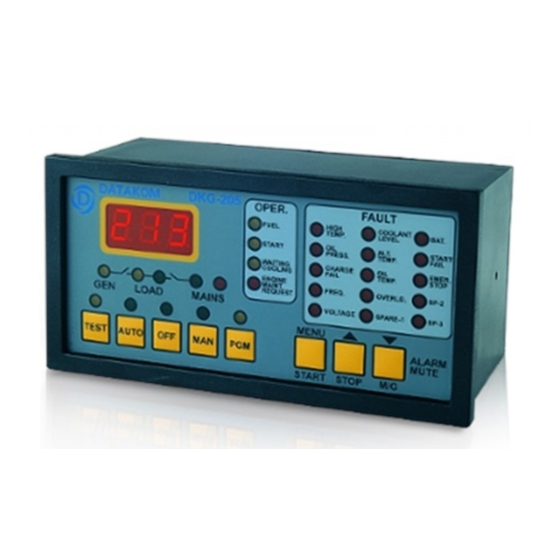
2. INSTALLATION 2.1 Introduction to the Control Panel The control panel is designed to provide user friendliness for both the installer and the user. Programming is usually unnecessary, as the factory settings have been carefully selected to fit most applications. However programmable parameters allow the complete control over the generating set. -
Page 5: Inputs And Outputs
1) ALWAYS remove the plug connectors when inserting wires with a screwdriver. 2) ALWAYS refer to the National Wiring Regulations when conducting installation. 3) An appropriate readily accessible disconnection devices (e.g. automatic fuses) MUST be provided as part of the installation. 4) The disconnection device must NOT be fitted in a flexible cord. - Page 6 2) STOP RELAY: The relay will operate during programmed period in order to stop the engine (Activate to Stop) 3) PREHEAT RELAY: The relay will operate the programmed delay before the cranking of the engine. It will be deactivated during cranking and reactivated during the rest period between cranks.
- Page 7 pressure. This input must be properly connected for the correct operation of the unit. If oil pressure is provided, the generator will not start and the oil pressure alarm indicator will flash. However, if the oil pressure is removed, the unit will resume normal operation.
-
Page 8: Digital Display
2.5 Digital Display This display shows: - (R) phase voltage, when mains are on - Alternator frequency, if the generator is on - Program values in program mode Below values can be read in sequence by pushing the MENU key in AUTO or TEST modes: - (R) phase voltage - (S) phase voltage... -
Page 9: Periodic Maintenance Request Display
(for example 200 hours), but even if this amount of engine hours is not fulfilled, it is performed after a given time limit (for example 12 months). The DKG-205 has both programmable engine hours and maintenance time limit. The engine hours is programmable between 0 and 750 hours at 50-hour steps, the time limit is programmable between 0 and 15 months. - Page 10 ALTERNATOR HIGH TEMPERATURE ALARM: It turns on if a signal comes from the high temperature switch of the alternator. WARNING: This switch shall be normally closed, and open in case of excess of heat. If this input is not used, connect it to DC Supply negative terminal, else an alarm will be given continuously.
-
Page 11: Modes Of Operation
2.9 Modes of Operation The modes of operation are selected by pushing the front panel keys. If the mode is changed while the engine is running, it will be stopped. Do not change the operation mode while the generator is in operation. OFF: In this mode, the mains contactor will be energized if mains phase voltages are within the programmed limits. -
Page 12: Maintenance
PROGRAM: It is used to program the timers, operational limits and the configuration. 3. MAINTENANCE WARNING: DO NOT OPEN THE UNIT There are NO serviceable parts inside the unit. Wipe the unit, if necessary with a soft damp cloth. Do not use chemical agents. - Page 13 When the AC mains fails the unit energizes the fuel solenoid, but does not start, also OIL PRESSURE ALARM led flashes: The unit is not supplied with battery (-) voltage at the oil pressure input. -Oil pressure switch not connected. -Oil pressure switch connection wire cut.
-
Page 14: Programming
5. PROGRAMMING The programming mode is used to program the timers, operational limits and the configuration of the unit. To enter the program mode, press the PGM button. The display shows (Pr) when program mode is selected. When the MENU key is pressed the program number will be displayed, when it is released the program value will be shown. - Page 15 P14=MAINS WAITING TIMER: This is the time between the mains voltages entered within the limits and the generator contactor is deactivated. P15=COOLING TIMER: This is the period that the generator runs for cooling purpose after the load is transferred to mains. P16=MAINS CONTACTOR TIMER: This is the period after the generator contactor has been deactivated and before the mains contactor has been activated.
-
Page 16: Calibration
6. CALIBRATION To enter the calibration mode, hold pressed the OFF button, then press PGM button. The rightmost decimal point of the voltage display will turn on. For following operations it is necessary to display the proper parameter by pressing the MENU key, and modify it by pressing using () and () keys. For more detailed explanation please refer to programming chapter of the user's manual. -
Page 17: Technical Specifications
7. TECHNICAL SPECIFICATIONS Step Control : 8 bit microprocessor. Mains Voltage: 277V (Ph-N) Mains Frequency: 50/60Hz. Power System Type: TN or TT. Alternator Voltage: 277V (Ph-N) Alternator Frequency: 0-100Hz. Measurement Category: CAT II DC Supply Range: 9.0 to 33.0 V-DC. 4.0 to 33.0 V-DC while cranking Current Consumption: 100 mA-DC typical (AUTO, mains OK,24volts) 250 mA-DC max. -
Page 18: Declaration Of Conformity
8. DECLARATION OF CONFORMITY The unit conforms to the EU directives -73/23/EEC and 93/68/EEC (low voltage) -89/336/EEC, 92/31/EEC and 93/68/EEC (electro-magnetic compatibility) Norms of reference: EN 61010 (safety requirements) EN 50081-2 (EMC requirements) EN 50082-2 (EMC requirements) The CE mark indicates that this product complies with the European requirements for safety, health environmental and customer protection. -
Page 19: Connection Diagram
9. CONNECTION DIAGRAM - 19 -... - Page 20 DATAKOM Electronics Limited Tel : +90-216-466 84 60 Fax : +90-216-364 65 65 e-mail : datakom@datakom.com.tr website: www.datakom.com.tr DATAKOM reserves the right of making modifications to the unit without prior notice. - 20 -...
Need help?
Do you have a question about the DKG-205 and is the answer not in the manual?
Questions and answers