Table of Contents
Advertisement
Quick Links
One Technology Way • P.O. Box 9106 • Norwood, MA 02062-9106, U.S.A. • Tel: 781.329.4700 • Fax: 781.461.3113 • www.analog.com
EVAL-ADUCM331QSPZ
DEVELOPMENT SYSTEM KIT CONTENTS
Evaluation board (EVAL-ADUCM331QSPZ) that facilitates
evaluation of the device with minimum external
components
Analog Devices, Inc., J-Link OB emulator
(USB-SWD/UART-EMUZ)
USB cable
INTRODUCTION
The
ADuCM330/ADuCM331
data acquisition systems incorporating dual, high performance,
Σ-Δ analog-to-digital converters (ADCs), with a 32-bit ARM
Cortex™-M3 processor and Flash/EE memory on a single chip.
The
ADuCM330/ADuCM331
for battery monitoring in 12 V automotive applications. The
ADuCM330/ADuCM331
integrate all of the required features
to precisely and intelligently monitor, process, and diagnose
12 V battery parameters including battery current, voltage, and
temperature over a wide range of operating conditions. The
ADuCM330
has 96 kB program flash, and the
128 kB program flash.
PLEASE SEE THE LAST PAGE FOR AN IMPORTANT
WARNING AND LEGAL TERMS AND CONDITIONS.
Development System Getting Started Tutorial
are fully integrated, 8 kSPS,
are complete system solutions
ADuCM331
EVAL-ADUCM331QSPZ
EVAL-ADUCM331QSPZ User Guide
GENERAL DESCRIPTION
The
EVAL-ADUCM331QSPZ
both the
ADuCM330
platform for evaluation of the
It allows quick removal and insertion of a device via a 32-lead
LFCSP socket. It also provides the connections necessary to allow
rapid measurement setups. Switches and LEDs are provided on
the applications board to assist in debugging and simple code
development. Sample code projects are also provided to show
key features of each peripheral and examples of how they can
be configured.
This user guide provides step-by-step details of how to set up
and configure the example software available on the
Design Tools
By working through this user guide, users can start to generate
and download their own user code for use in their own, unique
end-system requirements.
Full specifications on the
the product data sheet, which should be consulted in conjunction
has
with this user guide when working with the evaluation board.
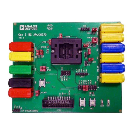
SOCKETED EVALUATION BOARD SETUP
PIN 1
Figure 1.
Rev. 0 | Page 1 of 6
development system supports
and the
ADuCM331
ADuCM330/ADuCM331
page.
ADuCM330/ADuCM331
UG-718
and allows a flexible
silicon.
ADuCM33x
are available in
Advertisement
Table of Contents

Related Manuals for Analog Devices EVAL-ADUCM331QSPZ


Summary of Contents for Analog Devices EVAL-ADUCM331QSPZ
-
Page 1: Development System Kit Contents
One Technology Way • P.O. Box 9106 • Norwood, MA 02062-9106, U.S.A. • Tel: 781.329.4700 • Fax: 781.461.3113 • www.analog.com EVAL-ADUCM331QSPZ Development System Getting Started Tutorial DEVELOPMENT SYSTEM KIT CONTENTS GENERAL DESCRIPTION EVAL-ADUCM331QSPZ development system supports Evaluation board (EVAL-ADUCM331QSPZ) that facilitates evaluation of the device with minimum external both the ADuCM330 and the ADuCM331 and allows a flexible... -
Page 2: Table Of Contents
Introduction ..................1 Verifying the J-Link Driver ............3 General Description ................. 1 Connect the Development System ..........4 EVAL-ADUCM331QSPZ Socketed Evaluation Board Setup ..1 Jumper Functionality ..............4 Revision History ................2 Keil μVision5 Integrated Development Environment ....5 Getting Started .................. 3 Introduction ...................5... -
Page 3: Getting Started
EVAL-ADUCM331QSPZ User Guide UG-718 GETTING STARTED SOFTWARE INSTALLATION PROCEDURE VERIFYING THE J-LINK DRIVER Items required to get started are as follows: Installing the J-Link driver is a three-step process. Follow the sequence of instructions provided by Segger to Keil μVision v5 or higher ... -
Page 4: Connect The Development System
UG-718 EVAL-ADUCM331QSPZ User Guide CONNECT THE DEVELOPMENT SYSTEM To connect the development system, take the following steps: Ensure that the GPIO5 jumper is in place (beside the LIN jumper). The GPIO5 jumper is used by the on-board Ensuring correct orientation, insert an ADuCM330/ kernel to determine program flow after a reset. -
Page 5: Keil Μvision5 Integrated Development Environment
In the right-hand side of the window, under the Devices code. The ADuCM330/ADuCM331 development system tab, click Analog Devices > ADuCM33x Series > supports nonintrusive emulation limited to 32 kB code. This ADuCM330. section describes the project setup steps to download and debug... - Page 6 By using the evaluation board discussed herein (together with any tools, components documentation or support materials, the “Evaluation Board”), you are agreeing to be bound by the terms and conditions set forth below (“Agreement”) unless you have purchased the Evaluation Board, in which case the Analog Devices Standard Terms and Conditions of Sale shall govern. Do not use the Evaluation Board until you have read and agreed to the Agreement.
Need help?
Do you have a question about the EVAL-ADUCM331QSPZ and is the answer not in the manual?
Questions and answers