Table of Contents
Advertisement
Quick Links
FEATURES
Full featured evaluation board for the
►
Easy connection to test equipment
►
Thru line for calibration
►
EQUIPMENT NEEDED
DC power supplies
►
Network analyzer
►
GENERAL DESCRIPTION
The ADRF5534 is an integrated RF, front-end multichip module
designed for time division duplex (TDD) applications. The device
operates from 3.1 GHz to 4.2 GHz. The ADRF5534 is configured
with an LNA and a high-power, silicon, SPDT switch.
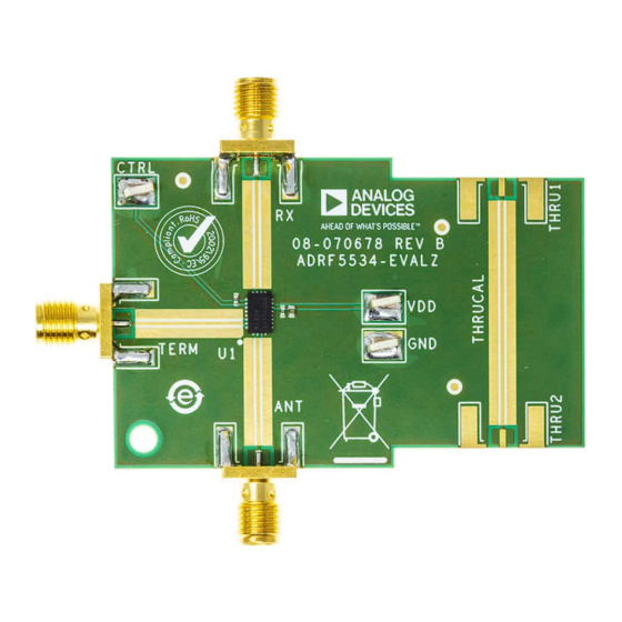
This user guide describes the ADRF5534-EVALZ, designed to
easily evaluate the features and performance of the ADRF5534. A
photograph of the ADRF5534-EVALZ is shown in
Full details about the device are available in the ADRF5534 data
sheet, which must be consulted when using the ADRF5534-EVALZ.
PLEASE SEE THE LAST PAGE FOR AN IMPORTANT
WARNING AND LEGAL TERMS AND CONDITIONS.
Evaluating the ADRF5534, 3.1 GHz to 4.2 GHz, Receiver Front End
ADRF5534
Figure
1.
User Guide | EVAL-ADRF5534
EVALUATION BOARD PHOTOGRAPH
Figure 1. ADRF5534-EVALZ
UG-2098
Rev. 0 | 1 of 7
Advertisement
Table of Contents

Subscribe to Our Youtube Channel
Related Manuals for Analog Devices EVAL-ADRF5534


Summary of Contents for Analog Devices EVAL-ADRF5534
- Page 1 User Guide | EVAL-ADRF5534 UG-2098 Evaluating the ADRF5534, 3.1 GHz to 4.2 GHz, Receiver Front End FEATURES EVALUATION BOARD PHOTOGRAPH Full featured evaluation board for the ADRF5534 ► Easy connection to test equipment ► Thru line for calibration ► EQUIPMENT NEEDED DC power supplies ►...
- Page 2 User Guide EVAL-ADRF5534 TABLE OF CONTENTS Features..............1 Power Supply and Control Inputs.......3 Equipment Needed..........1 Test Procedure............4 General Description..........1 Biasing Sequence..........4 Evaluation Board Photograph........1 Expected Results..........5 Evaluation Board Hardware........3 Evaluation Board Artwork and Schematic..... 6 Overview............3 Ordering Information..........7...
- Page 3 User Guide EVAL-ADRF5534 EVALUATION BOARD HARDWARE OVERVIEW RF INPUTS AND OUTPUTS The ADRF5534-EVALZ is preinstalled with connectors (end launch The ADRF5534-EVALZ has five edge mounted SMA connectors Subminiature Version A (SMA)) and assembled with the ADRF5534 for the RF inputs and outputs, as shown in Table 1.
- Page 4 User Guide EVAL-ADRF5534 TEST PROCEDURE Additional test equipment is needed to fully evaluate the device BIASING SEQUENCE functions and performance. To bias up the ADRF5534-EVALZ, perform the following steps: For noise figure evaluation, use either a noise figure analyzer or a 1.
- Page 5 User Guide EVAL-ADRF5534 TEST PROCEDURE EXPECTED RESULTS Figure 4. Gain vs. Frequency at Various Temperatures Figure 6. Insertion Loss vs. Frequency at Various Temperatures Figure 5. Receive Mode Return Loss vs. Frequency at Various Temperatures Figure 7. Transmit Mode Return Loss vs. Frequency at Various Temperatures analog.com...
- Page 6 User Guide EVAL-ADRF5534 EVALUATION BOARD ARTWORK AND SCHEMATIC Figure 8. Assembly Diagram Figure 9. Schematic analog.com Rev. 0 | 6 of 7...
- Page 7 Evaluation Board until you have read and agreed to the Agreement. Your use of the Evaluation Board shall signify your acceptance of the Agreement. This Agreement is made by and between you (“Customer”) and Analog Devices, Inc. (“ADI”), with its principal place of business at Subject to the terms and conditions of the Agreement, ADI hereby grants to Customer a free, limited, personal, temporary, non-exclusive, non-sublicensable, non-transferable license to use the Evaluation Board FOR EVALUATION PURPOSES ONLY.
Need help?
Do you have a question about the EVAL-ADRF5534 and is the answer not in the manual?
Questions and answers