Table of Contents
Advertisement
Quick Links
One Technology Way • P.O. Box 9106 • Norwood, MA 02062-9106, U.S.A. • Tel: 781.329.4700 • Fax: 781.461.3113 • www.analog.com
EVAL-ADUCM300QSPZ Development System Getting Started Tutorial
DEVELOPMENT SYSTEM KIT CONTENTS
Evaluation board (EVAL-ADUCM300QSPZ) that facilitates
evaluation of the device with minimum external
components
Analog Devices, Inc., J-Link OB emulator
(USB-SWD/UART-EMUZ)
USB cable
INTRODUCTION
The
ADuCM300
is a fully integrated, 8 kSPS, data acquisition
system that incorporates dual, high performance, multichannel,
Σ-Δ analog-to-digital converters (ADCs), a 32-bit Arm®
Cortex®-M3 processor, and flash memory. The
a 128 kB program flash, 4 kB data flash, and 6 kB static random
access memory (SRAM).
The
ADuCM300
is fully qualified for general automotive sensing
applications and can interface to multiple external precision
sensors in a system solution that also integrates a programmable
Cortex-M3 microcontroller to postprocess the sensor signals
on-chip, before transmitting the results off chip via industry-
standard wired interfaces.
PLEASE SEE THE LAST PAGE FOR AN IMPORTANT
WARNING AND LEGAL TERMS AND CONDITIONS.
ADuCM300
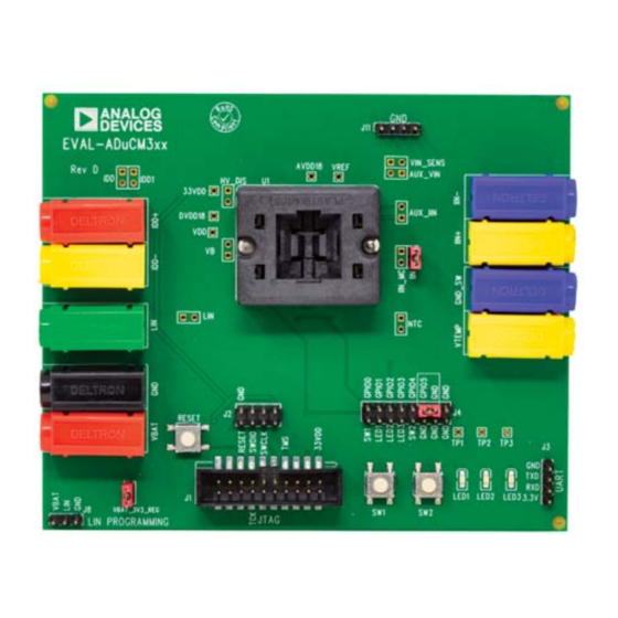
EVAL-ADUCM300QSPZ SOCKETED EVALUATION BOARD SETUP
EVAL-ADUCM300QSPZ
The
ADuCM300
precisely and intelligently interface, monitor, process, and
diagnose a precision sensing system over a wide range of
operating conditions.
The EVAL-ADUCM300QSPZ development system supports the
ADuCM300
and allows a flexible platform for evaluation of the
ADuCM300
silicon. The evaluation board allows quick removal
and insertion of a device via a 32-lead lead frame chip scale package
(LFCSP) socket and provides the connections necessary to allow
rapid measurement setups. Switches and LEDs are provided on
the evaluation board to assist in debugging and simple code deve-
lopment. Sample code projects are also provided to illustrate key
has
features of each peripheral and examples of how these peripherals
can be configured.
This user guide provides step-by-step details of how to set up
and configure the example software, available from the Tools &
Simulation section of the
By working through this user guide, users can start to generate
and download their own user code for use in their own, unique
end-system requirements.
For full details, see the
consulted in conjunction with this user guide when working
with the evaluation board.
Figure 1.
Rev. 0 | Page 1 of 6
User Guide
integrates all of the required features to
ADuCM300
product page.
ADuCM300
data sheet, which must be
UG-1544
Advertisement
Table of Contents

Related Manuals for Analog Devices EVAL-ADUCM300QSPZ


Summary of Contents for Analog Devices EVAL-ADUCM300QSPZ
- Page 1 User Guide UG-1544 One Technology Way • P.O. Box 9106 • Norwood, MA 02062-9106, U.S.A. • Tel: 781.329.4700 • Fax: 781.461.3113 • www.analog.com EVAL-ADUCM300QSPZ Development System Getting Started Tutorial ADuCM300 integrates all of the required features to DEVELOPMENT SYSTEM KIT CONTENTS...
- Page 2 Development System Kit Contents ..........1 Software Installation Procedure ..........3 Introduction ..................1 Verifying the J-Link Driver ............3 EVAL-ADUCM300QSPZ Socketed Evaluation Board Setup ..1 Connect the Development System ..........4 Revision History ................2 Keil μVision5 Integrated Development Environment ....5 Evaluation Board Quick Start Procedures ........
- Page 3 EVAL-ADUCM300QSPZ User Guide UG-1544 EVALUATION BOARD QUICK START PROCEDURES SOFTWARE INSTALLATION PROCEDURE VERIFYING THE J-LINK DRIVER The following items are required to begin the software To install the J-Link driver, take the following steps: installation procedure: Follow the sequence of instructions provided by Segger to ...
- Page 4 UG-1544 EVAL-ADUCM300QSPZ User Guide CONNECT THE DEVELOPMENT SYSTEM To connect the development system, take the following steps: Connect the debugger/programmer, noting the proper orientation, as shown in Figure 4. Ensure proper orientation and insert an ADuCM300 device. Connect the board supply voltage (12 V dc) between the Note that Pin 1 of the device is indicated by a dot in the VBAT and GND banana sockets.
- Page 5 UG-1544 KEIL μVISION5 INTEGRATED DEVELOPMENT ENVIRONMENT The Keil μVision5 integrated development environment (IDE) In the Devices tab, click Analog Devices > ADuCM300 integrates all the tools necessary to edit, assemble, and debug Series > ADuCM300 (see Figure 8). code. The...
- Page 6 By using the evaluation board discussed herein (together with any tools, components documentation or support materials, the “Evaluation Board”), you are agreeing to be bound by the terms and conditions set forth below (“Agreement”) unless you have purchased the Evaluation Board, in which case the Analog Devices Standard Terms and Conditions of Sale shall govern. Do not use the Evaluation Board until you have read and agreed to the Agreement.
Need help?
Do you have a question about the EVAL-ADUCM300QSPZ and is the answer not in the manual?
Questions and answers