Table of Contents
Advertisement
Quick Links
WSC 104 S AR
CompactSmoke
Installation instruction
For firmware version from 1.05
(Version 2310)
Save this installation instruction to the end-user
The latest version of this document can always be found on our website
UK
+44 (0) 1536 614 070
IE
+353 1903 9455
Other markets
+45 4567 0300
WSC 104 S AR install 2310 - UK
©WindowMaster 2023 ®WindowMaster is a registred trademark used under the license by WindowMaster International A/S
WindowMaster International A/S, Skelstedet 13, DK-2950 Vedbæk
™
info.uk@windowmaster.com
info.ie@windowmaster.com
info.dk@windowmaster.com
www.windowmaster.com
Advertisement
Table of Contents

Subscribe to Our Youtube Channel
Related Manuals for Window Master CompactSmoke WSC 104 S AR


Summary of Contents for Window Master CompactSmoke WSC 104 S AR
- Page 1 WSC 104 S AR ™ CompactSmoke Installation instruction For firmware version from 1.05 (Version 2310) Save this installation instruction to the end-user The latest version of this document can always be found on our website +44 (0) 1536 614 070 info.uk@windowmaster.com +353 1903 9455 info.ie@windowmaster.com...
-
Page 2: Table Of Contents
1 Safety information ................................ 3 Safety ................................3 230V AC ................................3 Back-up batteries .............................. 3 Application ................................. 3 Cable routing and electrical connection ......................3 2 Structure of the smoke panel ............................4 3 Max numbers of actuators per motor line and panel ....................4 4 Accessories and spare parts ............................ -
Page 3: Safety Information
Safety information Safety Only allow correspondingly trained, qualified and skilled personnel to carry out installation work. Reliable operation and the avoidance of damage and hazards are only guaranteed if installation and settings are carried out carefully in accordance with these instructions. There may be personal danger by electrically operated windows: - the forces occurring in the automatic mode can be such that parts of the body could get crushed - when opened, actuators (spindles) could protrude into the room... -
Page 4: Structure Of The Smoke Panel
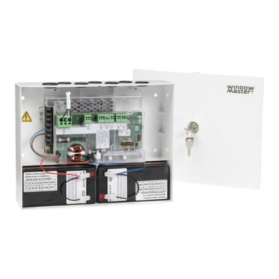
Structure of the smoke panel The WSC 104 contains a power supply unit (SMPS) type WCA 1P1, and a main card type WSA 1SS with input, output, and auxiliary supply (AUX). The main card type WSA 1SS allows connections of 1 motor line and 1 keypad. ®... -
Page 5: Accessories And Spare Parts
® ± 24V Actuator MotorLink Actuator WMS 409 xxxx 01 WMS 409-1 WMS 409-2 WMU 831 / 836 / 851-1 WMU 831 / 836 / 851-2 WMU 831 / 836 / 851-3 WMU 831 / 836 / 851-4 WMU 861-1 WMU 861-2 WMU 861-3 WMU 861-4... -
Page 6: Technical Data
Smoke detector WSA 311 Rain sensor WLA 331 Rain/wind speed sensor WLA 330 End of line motor module WSA 514 End of line smoke detector module (10kΩ resistor), 10 pcs. WSA 501 Cable glands WSA 133 Cables for smoke ventilation – see separate data sheet for further information WLL 8xx Comfort keypad for 1 window or 1 window group WSK 110 0A0B... -
Page 7: Mounting
LED message OK, fault and alarm Green all OK Yellow fault fire Reopening the actuators Every 2.min. in 30min. after a SHE open (selectable) Pre-set: no reopening Connection cable Actuators flexible max 6 mm² / solide max 10 mm² Other min 0,2mm²... -
Page 8: Installation
Installation Cable routing For cable routing we recommend the use of fire protected cables retaining their function E90 or E30. See also chapter 8 “Cable dimensioning” in this instruction. However, this has to be agreed with the Engineer or, if necessary, with the local fire protection department. Do not reduce the cable cross sections specified in the cable lengths table. -
Page 9: Cable Dimensioning
Cable dimensioning Maintaining the cable functions According to valid national regulations. The cable network for smoke ventilation systems (“Cable system“) ends normally at the interface (junction box) for the actuator! The flexible, heat resistant connection cable of actuator is part of the system component‚ electric actuator actuation, and is not a part of the electrical installation! We recommend in all cases to discuss the type of cable routing with the competent firefighting authorities. -
Page 10: Max Cable Length - Pyrotechnic Gas Generator
Furthermore, when using a 5-core cable, the distance between ”–” and ”Com” must be the same as the distance between ”+” and ”Com”. Meaning if L2 e.g. is being used as ”Com” L1 and L3 must be used for ”+” and ”-”. ®... -
Page 11: Cable Plan For Connection To Wsc 104
Cable plan for connection to WSC 104 The above plan shows the WSC 104 with ±24V standard actuators connected. Description of card and mains connection The panel includes a power supply unit (SMPS) and a main card. 10.1 Mains connection and power supply (WCA 1P1) WCA 1P1 - 100W SMPS unit The power supply is located under the main card. -
Page 12: Main Card Wsa 1Ss
10.2 Main card WSA 1SS The WSA 1SS contains the following: - 1 motor line for ±24V ® standard or MotorLink actuators - 1 input for keypads for comfort ventilation - 1 input for break glass units - 1 input for smoke detector - output for alarm signal - output for fault signal to Fire Alarm System... - Page 13 Standard actuators Connection of standard actuators on motor line X1 (with cable monitoring) ±24V Examples with 4A power consumption a) 4 pcs. WMX 826-1 b) 2 sets of 2 pcs. WMX 826-2 c) 1 pcs. WMU 884-1 Cable monitoring When using ±24V standard actuators or non-WindowMaster actuators and cable monitoring is wanted an “end of line motor...
- Page 14 Pyrotechnic gas generator or electromagnetic release When a pyrotechnic gas generator or an electromagnetic release is connected to the smoke panel, DIP-switch 8 must be set to ON, see “DIP-Switch configuration”. A pyrotechnic gas generator is connected to the smoke panel via the motor line and PE. An electromagnetic release is connected to the smoke panel via the motor line.
- Page 15 For connection of break glass unit type WSK 50x. Data 5.1 24V 5.2 Communication 5.3 0V Up to 5 break glass units type WSK 503 or WSK 504 can be connected to the line. If keypad and smoke detector are to be connected to the break glass unit, WSK 501 or WSK 502 are to be used. Max one of these break glass unit on the panel, the remaining units (up to four) must be of type WSC 503 or WSC 504.
- Page 16 Connection of different types of smoke detectors to CompactSmoke™ Smoke detector type WSA 300 WSA 311 Hekatron Hekatron MSD 523 SSD 521/a (max 5 pcs) (WSA 200 6101) X6.1 L1 In In + Connect to WSA 1SS X6.2 Com - Com - Connect to WSK In +...
- Page 17 Solid state output for transmission of fault signal to Fire Alarm System Data Normally closed. Open = Fault Solid state output for transmission of fault signal to Fire Alarm System. A fault must last min 20 seconds before the relay indicate a fault. Data Max voltage: 30 Vp (peak) Max output: 150 mA...
-
Page 18: Dip Switch Configuration
Shows the status of the panel = alarm Yellow = fault Green fast flickering = all OK (CPU working), Green constant = CPU communication stopped (possible reset or contact WindowMaster) Close / open all windows. When pressed together right after power has been connected the panel configures / ↓... -
Page 19: Back-Up Batteries
Back-up batteries Connect 2 pcs. back-up batteries type WSA 003 See section 17 “Maintenance” for further information. Panel with back–up batteries. Configuration of panel The smoke panel is configured by pressing the two keys ”↑” and ”↓” on the main card, at the same time for 5-10 seconds. The smoke panel must be configured After re-installation, changes, or change of actuators ®... -
Page 20: Local Output
13.1.4 Local output The output on the panel is pre-configured with the function as shown below. X7 Alarm signal X8 Fault signal to fire alarm system Fault detection via LED 14.1 Fault detection on the smoke panel In case of error on the panel, the yellow diode on the main card will blink and via blink sequence indicate an error message. Depending on the type of error, the message will consist of 2 or 3 blink sequences, separated by a seconds pause. -
Page 21: Fault Indication On Break Glass Unit
Error message 1. Blink sequence 2. Blink sequence 3. Blink sequence Number Number Number Error on Error on or error type Error type of blinks of blinks of blinks Closed ring – the standard version does not allow break glass units connected in a closed ring, check connection of break glass units and disconnect the ring and re-configure Problem on X5 (break glass unit) –... -
Page 22: Commissioning And Test Run
15.1.1 Blown fuses – 6.3A slow An error on the ”Battery status” can also be triggered if the battery-fuse (6.3A slow) is blown. Additionally, an error on the motor line status can be triggered if the motor line-fuse (6.3A slow) is blown. The battery-fuse is located in the bottom right above the connection to the back-up battery. -
Page 23: Smoke Detectors
16.6 Smoke detectors a) Spray test aerosol on the smoke detectors (aerosol item no. 9549). b) The actuators move open through to the end position. The red LED in the smoke detector, the red alarm LED (also in the smoke ventilation panel) and the permanent acoustic signal in the break glass unit are ON. c) Press the Reset/Closed button in the break glass unit - the actuators close through to the end position. -
Page 24: Replacement 1Ss Card
17.2 Replacement 1SS card 1. Disconnect the 230 V and the batteries. 2. Insert the 1SS replacement card. 3. Turn on the 230 V and connect the batteries. 4. Configure the panel again, see chapter 13 – Configuration of panel. 5.
Need help?
Do you have a question about the CompactSmoke WSC 104 S AR and is the answer not in the manual?
Questions and answers