Sign In
Upload
Manuals
Brands
BINDER Manuals
Oven
M 720
BINDER M 720 Manuals
Manuals and User Guides for BINDER M 720. We have
3
BINDER M 720 manuals available for free PDF download: Operating Manual
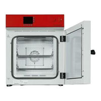
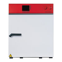
Binder M 720 Operating Manual (137 pages)
Drying and heating ovens with forced convection and advanced program functions
Brand:
Binder
| Category:
Laboratory Equipment
| Size: 11 MB
Table of Contents
Table of Contents
2
Safety
6
Personnel Qualification
6
Operating Manual
6
Legal Considerations
6
Intellectual Property
7
Structure of the Safety Instructions
7
Signal Word Panel
7
Safety Alert Symbol
8
Pictograms
8
Word Message Panel Structure
9
Localization / Position of Safety Labels on the Chamber
9
Type Plate
10
UKCA Label
11
General Safety Instructions on Installing and Operating the Chambers
11
Intended Use
13
Foreseeable Misuse
14
Residual Risks
15
Operating Instructions
16
Measures to Prevent Accidents
16
Chamber Description
17
Chamber Overview
18
Chamber Rear
19
Triangular Instrument Panel
20
Main Power Switch (Sizes 260 and 720)
20
Zero-Voltage Switching Contact
20
Completeness of Delivery, Transportation, Storage, and Installation
21
Unpacking, and Checking Equipment and Completeness of Delivery
21
Guidelines for Safe Lifting and Transportation
22
Storage
22
Location of Installation and Ambient Conditions
22
Installation
24
Electrical Connection
24
Connection to an Exhaust/Ventilation System (Optional)
25
Inserting the Racks
25
Functional Overview of the Mb2 Chamber Controller
26
Operating Functions in Normal Display
27
Display Views: Normal Display, Program Display, Chart-Recorder Display
28
Controller Icons Overview
29
Operating Modes
31
Controller Menu Structure
32
Main Menu
33
Settings" Submenu
34
Service" Submenu
34
Principle of Controller Entries
35
Performance During and after Power Failures
35
Performance When Opening the Door
36
Failsafe Function
36
Start up
36
Turning on the Chamber
36
Controller Settings Upon Start up
36
Loading
37
Set-Point Entry in "Fixed Value" Operating Mode
38
Set-Point Entry for Temperature and Fan Speed through the "Setpoints" Menu
38
Adjusting the Air Flap Position through the "Setpoints" Menu
39
Direct Setpoint Entry Via Normal Display
40
Special Controller Functions Via Operation Lines
41
Timer Program: Stopwatch Function
42
Starting a Timer Program
42
Performance During Program Delay Time
42
Stopping a Running Timer Program
43
Pausing a Running Timer Program
43
Cancelling a Running Timer Program
43
Performance after the End of the Program
43
Time Programs
44
Starting an Existing Time Program
44
Performance During Program Delay Time
45
Stopping a Running Time Program
45
Pausing a Running Time Program
45
Cancelling a Running Time Program
45
Performance after the End of the Program
45
Creating a New Time Program
46
Program Editor: Program Management
46
Deleting a Time Program
47
Section Editor: Section Management
48
Add a New Program Section
49
Copy and Insert or Replace a Program Section
49
Deleting a Program Section
50
Value Entry for a Program Section
51
Section Duration
51
Set-Point Ramp and Set-Point Step
52
Special Controller Functions Via Operation Lines
53
Setpoint Entry for Temperature and Fan Speed, Setting the Air Flap Position
54
Tolerance Ranges
55
Repeating One or Several Sections Within a Time Program
55
Saving the Time Program
56
Week Programs
57
Starting an Existing Week Program
57
Cancelling a Running Week Program
57
Creating a New Week Program
58
Program Editor: Program Management
59
Deleting a Week Program
60
Section Editor: Section Management
61
Add a New Program Section
62
Copy and Insert or Replace a Program Section
62
Deleting a Program Section
63
Value Entry for a Program Section
63
Set-Point Ramp and Set-Point Step Modes
63
Weekday
64
Start Time
64
Setpoint Entry for Temperature and Fan Speed, Setting the Air Flap Position
65
Special Controller Functions Via Operation Lines
65
Notification and Alarm Functions
66
Notification and Alarm Messages Overview
66
Notifications
66
Alarm Messages
67
State of Alarm
67
Resetting an Alarm, List of Active Alarms
68
Tolerance Range Settings
68
Activating / Deactivating the Audible Alarm (Alarm Buzzer)
69
Overtemperature Protection
70
Overtemperature Protective Device Class 1
70
Message and Measures in the State of Alarm
70
Overtemperature Safety Controller Class 2 / 3.1
71
Selecting between Safety Controller Class 2 (Temperature Limiter) or Class 3.1
72
Safety Controller Mode
72
Setting the Safety Controller
73
Message and Measures in the State of Alarm
73
Function Check
74
Zero-Voltage Relay Alarm Contact
75
User Management
76
Authorization Levels and Password Protection
76
Log in
79
Log out
80
User Change
80
Password Assignment and Password Change
81
Password Change
81
Deleting the Password for an Individual Authorization Level
83
New Password Assignment for "Service" or "Admin" Authorization Level When the Password Function was Deactivated
84
Activation Code
85
General Controller Settings
86
Selecting the Controller's Menu Language
86
Setting Date and Time
86
Selecting the Temperature Unit
88
Display Configuration
88
Adapting the Display Parameters
88
Touchscreen Calibration
89
Network and Communication
90
Ethernet
90
Configuration
90
Display of the MAC Address
91
Web Server
91
E-Mail
92
USB Menu: Data Transfer Via USB Interface
93
General Information
94
Service Contact Page
94
Current Operating Parameters
94
Event List
95
Technical Chamber Information
95
Chart Recorder Display
96
Views
96
Show and Hide Legend
96
Switch between Legend
96
Show and Hide Specific Indications
97
History Display
97
Setting the Parameters
100
Options
101
APT-COM™ 4 Multi Management Software (Option)
101
Object Temperature Display with Flexible Pt100 Temperature Sensor (Option)
101
Object Temperature Control with Flexible Pt100 Temperature Sensor (Option)
102
Analog Output for Temperature (Option)
103
HEPA Fresh Air Filter (Option)
103
Mostly Gas-Tight Version (Option)
103
Inert Gas Connection with Mostly Gas-Tight Version (Option)
104
Cleaning and Decontamination
106
Cleaning
106
Decontamination / Chemical Disinfection
108
Maintenance and Service, Troubleshooting, Repair, Testing
109
General Information, Personnel Qualification
109
Maintenance Intervals, Service
109
Simple Troubleshooting
110
Sending the Chamber Back to BINDER Gmbh
112
Disposal
113
Disposal of the Transport Packing
113
Decommissioning
113
Disposal of the Chamber in the Federal Republic of Germany
113
Disposal of the Chamber in the Member States of the EU Except for the Federal Republic of Germany
114
Disposal of the Chamber in Non-Member States of the EU
116
Technical Description
116
Factory Calibration and Adjustment
116
Definition of Usable Volume
116
Over Current Protection
117
M Technical Data
117
Equipment and Options (Extract)
119
Accessories and Spare Parts (Extract)
120
Dimensions Size 56
121
Dimensions Size 115
122
Dimensions Size 260
123
Dimensions Size 720
124
Certificates and Declarations of Conformity
125
EU Declaration of Conformity
125
UKCA Declaration of Conformity
128
Certificate for the GS Mark of Conformity of the "Deutsche Gesetzliche Unfallversicherung E.V." (German Social Accident Insurance) DGUV
129
Contamination Clearance Certificate
131
For Chambers Located Outside the USA and Canada
131
For Chambers Located in the USA and Canada
134
Advertisement
BINDER M 720 Operating Manual (71 pages)
Drying and heating ovens with forced convection and advanced program functions
Brand:
BINDER
| Category:
Oven
| Size: 5 MB
Table of Contents
Table of Contents
2
1 Safety
4
Legal Considerations
4
Structure of the Safety Instructions
4
Signal Word Panel
4
Safety Alert Symbol
5
Pictograms
5
Word Message Panel Structure
6
Localization / Position of Safety Labels on the Chamber
6
Type Plate
7
General Safety Instructions on Installing and Operating the Chambers
8
Intended Use
9
2 Chamber Description
10
Chamber Overview
11
Control Panel
12
3 Completeness of Delivery, Transportation, Storage, and Installation
12
Unpacking, and Checking Equipment and Completeness of Delivery
12
Guidelines for Safe Lifting and Transportation
13
Storage
13
Location of Installation and Ambient Conditions
14
4 Installation and Connections
15
Electrical Connection
15
Connection to a Suction Plant (Optional)
15
5 Start up
16
Function Overview of the MB1 Display Program Controller
16
Operating Modes
16
Performance after Power Failures
17
Turning on the Chamber
17
6 Controller Mb1 Settings
18
Selection of the Menu Language
18
Overview of Program Controller MB1 Displays
19
Menu Settings in the "User-Settings" Menu
20
Menu Settings in the "User Level" Menu
21
7 Graphic Representation of the Historical Measurement (Chart Recorder Function)
22
Setting the Storage Rate
24
8 Manual Mode
25
Entering the Set Point Values
25
Performance after Power Failure in Manual Mode
26
9 Program Operation
26
Menu-Based Program Entry
27
Selecting between Set-Point Ramp and Set-Point Step
29
Program Entry as Set-Point Ramp or as Set-Point Step
29
Information on Programming Different Temperature Transitions
32
Repetition of a Section or Several Sections Within a Program
33
Performance after Power Failure in Program Mode
33
Starting a Previously Entered Program
34
Deleting a Program
34
Temperature Profile Template
35
Program Table Template
36
10 Temperature Safety Devices
37
Temperature Safety Device Class 2 (DIN 12880)
37
Temperature Safety Device Class 3.1 (DIN 12880) (Available Via BINDER INDIVIDUAL Customized Solutions)
38
11 Options
39
APT-COM™ 4 Multi Management Software (Option)
39
Ethernet Interface
39
HEPA Fresh Air Filter (Option)
39
Data Logger Kit (Option)
40
Additional Flexible Pt100-Temperature Sensor (Option)
40
Analog Output for Temperature (Option)
40
Additional Measuring Channel for Digital Object Temperature Indicator with Flexible Temperature Sensor Pt 100 (Option)
41
Mostly Gas-Tight Version (Option for M 53 and M 115)
41
Inert Gas Connection with Mostly Gas-Tight Version (Option for M 53 and M 115)
42
Keyboard Locking (Option)
44
12 Maintenance, Cleaning, and Service
44
Maintenance Intervals, Service
44
Cleaning and Decontamination
45
Cleaning
45
Decontamination
47
Sending the Chamber Back to BINDER Gmbh
48
13 Disposal
48
Disposal of the Transport Packing
48
Decommissioning
49
Disposal of the Chamber in the Federal Republic of Germany
49
Disposal of the Chamber in the Member States of the EU Except for the Federal Republic of Germany
50
Disposal of the Chamber in Non-Member States of the EU
51
14 Troubleshooting
52
15 Technical Description
53
Factory Calibration and Adjustment
53
Definition of Usable Volume
53
Over Current Protection
54
Technical Data
54
Equipment and Options (Extract)
56
Accessories and Spare Parts (Extract)
57
Dimensions M 53
58
Dimensions M 115
59
Dimensions M 240
60
Dimensions M 400
61
Dimensions M 720
62
16 Eu Declaration of Conformity
63
17 Product Registration
65
18 Contamination Clearance Certificate
66
For Chambers Located Outside the USA and Canada
66
For Chambers Located in the USA and Canada
69
Binder M 720 Operating Manual (61 pages)
High performance temperature chambers with program control
Brand:
Binder
| Category:
Climate chamber
| Size: 2 MB
Table of Contents
Table of Contents
4
1 Safety
6
Legal Considerations
6
Structure of the Safety Instructions
6
Signal Word Panel
6
Safety Alert Symbol
7
Pictograms
7
Word Message Panel Structure
8
Localization / Position of Safety Labels at the Unit
8
Type Plate
9
General Safety Instructions on Installing and Operating the High Performance Temperature Chamber10
10
Intended Use
11
2 Unit Description
11
Unit Overview
12
Control Panel M
13
3 Scope of Delivery, Transportation, Storage, and Installation
13
Unpacking, and Checking Equipment and Scope of Delivery
13
Guidelines for Safe Lifting and Transportation
14
Storage
14
Location of Installation and Ambient Conditions
15
4 Installation and Connections
16
Electrical Connection
16
Connection to a Suction Plant (Optional)
16
5 Start up
16
Function Overview of Screen Program Controller MB1
17
Operating Modes
17
Behavior after Power Failure
18
Switching on the Unit
18
6 Settings of the Controller Mb1
19
Selection of the Menu Language
19
Function Overview Program Controller MB1
20
Settings in the Menu "User-Settings
21
Settings in the Menu "User Level
22
7 Graphical Representation of the Measurement Course (Chart Recorder Function)
23
Setting the Storage Rate
25
8 Manual Mode
26
Set-Point Entry
26
Behavior after Power Failure in Manual Mode
27
9 Program Operation
27
Overview Menu-Based Program Entry
28
Selecting between Set-Point Ramp and Set-Point Step
30
Program Entry as Set-Point Ramp or as Set-Point Step
30
Advice for the Programming of the Different Temperature Transitions
33
Repetition of a Section or Several Sections Within a Program
34
Behavior after Power Failure in Program Mode
34
Starting a Previously Entered Program
35
Deleting a Program
35
Temperature Profile Template
36
Program Table Template
37
10 Temperature Safety Devices
38
Temperature Safety Device Class 2.0 (DIN 12880)
38
Temperature Safety Device Class 3.1 (DIN 12880) (Option)
39
11 Options
40
Communication Software APT-COM™ 3 Datacontrolsystem (Option)
40
Analogue Output for Temperature (Option)
40
Keyboard Locking (Option)
40
HEPA Fresh Air Filter (Option)
41
Additional Pt100-Temperature Sensor, Fix or Flexible (Option)
41
Additional Measuring Channel for Digital Object Temperature Indicator with Flexible Temperature Sensor Pt 100 (Option)
41
Mostly Gas-Tight Version (Option for M 53 and M 115)
42
Inert Gas Connection (Option for M 53 and M 115)
42
12 Maintenance, Cleaning, and Service
43
Maintenance Intervals, Service
43
Cleaning and Decontamination
43
Sending Back the Unit to BINDER Gmbh
44
13 Disposal
45
Disposal of the Transport Packing
45
Decommissioning
45
Disposal of the Unit in the Federal Republic of Germany
46
Disposal of the Unit in the Member States of the EC Except for the Federal Republic of Germany
47
Disposal of the Unit in Non-Member States of the EC
48
14 Troubleshooting
49
15 Technical Description
50
Factory Calibration and Adjustment
50
Definition of Usable Space
50
Technical Data M
50
Equipment and Options M
52
Spare Parts
53
Dimensions M 53
54
Dimensions M 115
55
Dimensions M 240
56
Dimensions M 400
57
Dimensions M 720
58
16 Contamination Clearance Certificate
59
Advertisement
Advertisement
Related Products
BINDER M Series
BINDER M E2 Series
BINDER M 53
BINDER M 115
BINDER M 400
BINDER M 240
Binder M720-400V
Binder MKF720-400V
Binder MK720-400V
Binder M115-230V
BINDER Categories
Climate chamber
Laboratory Equipment
Accessories
Oven
Farm Equipment
More BINDER Manuals
Login
Sign In
OR
Sign in with Facebook
Sign in with Google
Upload manual
Upload from disk
Upload from URL