Binder VD 23 Operating Manual
Vd (e2.1)
vacuum drying oven
model version:
vd023-230v;
vd023ul-120v;
vd053-230v;
vd053ul-120v;
vd115-230v;
vd115ul-120v
Hide thumbs
Also See for VD 23:
- Mounting instructions (32 pages) ,
- Operating manual (173 pages) ,
- Operating manual (83 pages)
Table of Contents
Advertisement
Operating Manual
VD (E2.1)
Vacuum Drying Oven
with microprocessor program controller RD3
Model
VD 23
VD 23-UL
VD 53
VD 53-UL
VD 115
VD 115-UL
BINDER GmbH
Address: Post office box 102, 78502 Tuttlingen, Germany Phone: +49 7462 2005 0
Fax: +49 7462 2005 100 Internet: http://www.binder-world.com
E-mail: info@binder-world.com Service Hotline: +49 7462 2005 555
Service Fax: +49 7462 2005 93 555 Service E-Mail: service@binder-world.com
Service Hotline USA: +1 866 885 9794 or +1 631 224 4340 x3
Service Hotline Asia Pacific: +852 390 705 04 or +852 390 705 03
Service Hotline Russia and CIS: +7 495 988 15 16
Issue 07/2017
Model version
VD023-230V
VD023UL-120V
VD053-230V
VD053UL-120V
VD115-230V
VD115UL-120V
Art. No.
9030-0029, 9130-0029
9030-0035, 9130-0035
9030-0030, 9130-0030
9030-0036, 9130-0036
9030-0031, 9130-0031
9030-0037, 9130-0037
Art. No. 7001-0125
Advertisement
Table of Contents

Related Manuals for Binder VD 23


Summary of Contents for Binder VD 23
- Page 1 Fax: +49 7462 2005 100 Internet: http://www.binder-world.com E-mail: info@binder-world.com Service Hotline: +49 7462 2005 555 Service Fax: +49 7462 2005 93 555 Service E-Mail: service@binder-world.com Service Hotline USA: +1 866 885 9794 or +1 631 224 4340 x3 ...
-
Page 2: Table Of Contents
Intended use ............................. 11 DESCRIPTION OF THE EQUIPMENT ..............12 Chamber overview ..........................13 VD 23 control panel........................... 14 VD 53 / 115 control panel ......................... 14 Connections at the rear of the chamber ................... 15 COMPLETENESS OF DELIVERY, TRANSPORTATION, STORAGE, AND INSTALLATION .................... - Page 3 17.2.1 Cleaning ..........................66 17.2.2 Decontamination ........................67 17.3 Sending the chamber back to BINDER GmbH ................. 69 18. DISPOSAL......................69 18.1 Disposal of the transport packing ..................... 69 18.2 Decommissioning ..........................70 18.3 Disposal of the chamber in the Federal Republic of Germany ............70 18.4 Disposal of the chamber in the member states of the EU except for the Federal Republic of...
- Page 4 21. CERTIFICATES AND DECLARATIONS OF CONFORMITY ....... 83 21.1 EU Declaration of Conformity ......................83 21.2 Certificate for the GS mark of conformity of the “VDE Prüf- und Zertifizierungsinstitut” (Testing and Certification Institute of the Association for Electrical, Electronic and Information Technologies) ... 85 22.
-
Page 5: Safety
Understanding and observing the instructions in this operating manual are prerequisites for hazard-free use and safety during operation and maintenance. In no event shall BINDER be held liable for any damages, direct or incidental arising out of or related to the use of this manual. -
Page 6: Safety Alert Symbol
WARNING Indicates a potentially hazardous situation which, if not avoided, could result in death or serious (irreversible) injury. CAUTION Indicates a potentially hazardous situation which, if not avoided, may result in moderate or minor (reversible) injury. CAUTION Indicates a potentially hazardous situation, which, if not avoided, may result in damage to the product and/or its functions or to property in its proximity. -
Page 7: Word Message Panel Structure
(on the outer chamber door) Service label Figure 1: Position of labels on the chamber Keep safety labels complete and legible. Replace safety labels that are no longer legible. Contact BINDER Service for these replacements. VD (E2.1) 07/2017 page 7/96... -
Page 8: Type Plate
VD 23 Serial No. 00000000000000 Im Mittleren Ösch 5 Made in Germany E2.1 78532 Tuttlingen / Germany www.binder-world.com Figure 2: Type plate (example of VD 23 regular chamber) Indications of the type plate Information (example) BINDER Manufacturer: BINDER GmbH VD 23... -
Page 9: General Safety Instructions On Installing And Operating The Chamber
213-850 on safe working in laboratories (formerly BGI/GUV-I 850-0, BGR/GUV-R 120 or ZH 1/119, issued by the employers’ liability insurance association) (for Germany). BINDER GmbH is only responsible for the safety features of the chamber provided skilled electricians or qualified personnel authorized by BINDER perform all maintenance and repair, and if components relating to chamber safety are replaced in the event of failure with original spare parts. - Page 10 Any solvent contained in the charging material must not be explosive or inflammable. I.e., irrespective of the solvent concentration in the steam room, NO explosive mixture with air must form. The drying temperature must lie below the flash point or below the sublimation point of the charging material. Familiarize yourself with the physical and chemical properties of the charging material, as well as the contained moisture constituent and its behavior with the addition of heat energy and changes in pressure.
-
Page 11: Intended Use
The charging material shall not contain any corrosive ingredients that may damage the machine components made of stainless steel and aluminum. Such ingredients include in particular acids and halides. Any corrosive damage caused by such ingredients is excluded from liability by BINDER GmbH. DANGER Explosion or implosion hazard. -
Page 12: Description Of The Equipment
Description of the equipment Vacuum drying is used for special drying problems, for which conventional drying methods cannot offer a solution due to physical limitations. All functions of the multifunctional program control can be set simply and conveniently via the easy to understand function keypad of the RD3 temperature program controller. -
Page 13: Chamber Overview
Chamber overview Figure 3: VD 23 with option vacuum module and chemical membrane pump Control panel and instrument box Chamber door Elastic-mounted safety glass window Vacuum module (option) Chemical membrane pump (option) VD (E2.1) 07/2017 page 13/96... -
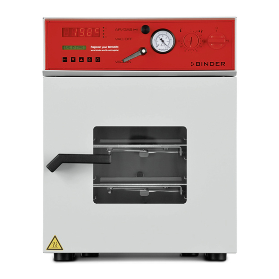
Page 14: Vd 23 Control Panel
VD 23 control panel (2a) AIR/GAS VAC.OFF VAC.ON Figure 4: VD 23 control panel On/off switch (main power switch) Temperature safety device class 2 (2a) Red alarm lamp of the safety device class 2 Manometer (pressure reading) Aeration valve (inert gas or ambient air) -
Page 15: Connections At The Rear Of The Chamber
Connections at the rear of the chamber (10) (11) (12) (13) (14) (15) (16) (9) (17) Figure 6: Rear of VD RS 422 serial interface for computer communication (10) Miniature fuse (11) Power connection line (12) Inert gas connection, adapter with hose olive ∅ 8 mm / 0.31 in (VD23: also fresh air inlet) (13) Vacuum connection with small flange DN16 (14) DIN socket (option) for option “object temperature display”... -
Page 16: Completeness Of Delivery, Transportation, Storage, And Installation
Note on second-hand chambers (Ex-Demo-Units): Second-hand chambers are chambers that were used for a short time for tests or exhibitions. They are thoroughly tested before resale. BINDER ensures that the chamber is technically sound and will work flawlessly. Second-hand chambers are marked with a sticker on the chamber door. Please remove the sticker before commissioning the chamber. -
Page 17: Guidelines For Safe Lifting And Transportation
Lift chambers size 115 with the aid of 6 people. • Permissible ambient temperature range during transport: -10 °C / 14°F to +60 °C / 140°F. You can order transport packing for moving or shipping purposes from BINDER Service. Storage Intermediate storage of the chamber in a closed and dry room. - Page 18 ∅ Do NOT operate the chamber in potentially explosive areas. KEEP explosive dust or air-solvent mixtures AWAY from the vicinity of the chamber. The maximum permissible ambient temperature of the vacuum pumps delivered by BINDER is 40 °C / 104°F.
-
Page 19: Installation And Connections
For connecting to the chamber, BINDER recommends the connection kit VD, Art. no. 8012-0146. With the option “stainless steel tubing” between the vacuum oven and vacuum module, the vacuum connection is already located inside the vacuum module. -
Page 20: Electrical Connection
Nominal voltage ± 10% at the Current Chamber Model Power plug type fuse indicated power frequency VD 23 230 V at 50 Hz VD 53 Shockproof plug 10 A 230 V at 60 Hz VD 115 VD 23-UL NEMA 5-15P... -
Page 21: Start Up
Start up After connecting the supply lines (chap 4), turn on the chamber via the main power switch (1): • Position 0: Oven without function • Position I: Oven operating Warming chambers may release odors in the first few days after commissioning. This is not a quality defect. -
Page 22: General Indications On The Rd3 Program Controller
(setting in the user level, chap. 10). This setting is then valid for all program sections. Programming can be done directly through the keypad of the controller or graphically through the software APT-COM™ 3 DataControlSystem (option, chap. 16.8) specially developed by BINDER. General indications on the RD3 program controller... - Page 23 Normal Display / Fixed value operation 5 seconds Fixed value entry mode Program editor Program start level 5 seconds Menu visible only if week program Week program editor timer is activated in the user level 5 seconds User level If no button is touched during more than 120 sec., the controller returns from the current level to Normal Display.
-
Page 24: Fixed Value Entry Mode
Fixed value entry mode If you do not want to use the week program timer, deactivate it (factory setting, setting in the user level, chap. 10) before entering any set-points. Any setting of the operation lines in fixed value entry mode is ineffective with active week program timer. Basic entry principle: Access the individual parameters with button X/W. -
Page 25: Week Program Editor
CAUTION Too high or too low temperature. Damage to the charging material. Deactivate the week program timer if you do not use it. Week program editor The Week program editor permits defining up to 4 shift point for each week day. A shift point defines a moment and the switching state ON or OFF of the channels that become active in this instance. - Page 26 Display 1 shows 0000 Display 2 shows Shiftpt. (no function) Press program key Display 1 shows 0000 Display 2 shows (selection of the shift point) Shiftpt. (actual shift point: 1) Select the shift point (1 up to 4) with key Value is shown in display 2.
-
Page 27: Program Table Template For Week Program Editor
Program table template for Week program Editor Program editor Program title Project Date: Day of the week Time Channel 1 Channel 2* (temperature) hh:mm ON = SP2 OFF = SP1 Monday Tuesday Wednesday Thursday Friday Saturday Sunday * Channel 2 is non-functional in the standard chamber VD (E2.1) 07/2017 page 27/96... -
Page 28: Programming Example Of The Week Program Editor
Programming example of the Week program editor 7.2.1 Desired time function During the day (12 hours) the oven shall maintain a temperature of +80 °C / 176°F, and during the night (12 hours) it shall cool down / stop heating (set-point 30 °C / 86°F). This program shall automatically run during the whole year, i.e. -
Page 29: Proceeding In Detail
7.2.3 Proceeding in detail 1. Settings in the user level • Activating the week program timer • Checking and, if necessary, setting the real time clock Normal Display Display 1 shows e.g. 39.8 (actual temperature value) Display 2 shows (actual date and time, actual switching state of week e.g. - Page 30 Display 1 shows e.g. 2006 (Actual setting: 2006) Display 2 shows Year 2006 (Setting the year of the real time clock) Set year (2006 up to 2050) using arrow Setting is shown in display 2. keys Press key Display 1 shows e.g.
- Page 31 Press key Display 1 shows 80.0 (actual temperature set-point 2) Display 2 shows SP2 TEMPERATURE (variable: temperature in °C) Value is shown in display 1. Enter temperature set-point 80 °C using arrow keys Press the EXIT button. The controller changes to Normal Display. 3.
- Page 32 Display 1 shows 06.00 (time of the selected shift point) (entry of time of the selected shift point) Display 2 shows Time 06:00 (actual setting: 6.00, i.e. 6 a.m.) Value is shown in display 2. Enter the time 06:00 using arrow keys Press key Display 1 shows 0000...
- Page 33 Display 1 shows 0000 (selection of day of the week) Display 2 shows Tuesday (actual selection: Tuesday) Day of the week is shown in display 2. Select the next day of the week (Tuesday) with key Press program key Display 1 shows 0000 Display 2 shows Shiftpt.
-
Page 34: Program Editor
Program editor Selecting between set-point ramp and set-point step You can program various kinds of temperature transitions. In the user level (chap. 10) you can select between the settings “Ramp” (default setting) and “Step”. Setting “Ramp” permits programming all kinds of temperature transitions. With setting “Step”... - Page 35 Program entry as set-point ramp (example): W/°C t/min. Program table corresponding to the diagram (with default setting “Ramp”): Section Temperature Section length Operation lines set-point [hh.mm] [ °C] TEMP TIME O.LINE 00:30 01:30 01:00 03:20 00:01 You can now enter the values of such a program table to the RD3 program controller (chap. 8.2). Program entry as set-point step (example): S01 S02 W/°C...
-
Page 36: Programming With Setting "Step
Program table corresponding to the diagram (with default setting “Ramp”): Section Temperature Section length Operation lines set-point [hh.mm] [ °C] TEMP TIME O.LINE 00:30 00:01 01:30 00:01 01:00 00:01 03:20 00:01 You can now enter the values of such a program table to the RD3 program controller (chap. 8.2). Program the end point of the desired cycle with an additional section (in our examples S05 for set-point ramp and S08 for set-point step) with a section time of at least one minute. -
Page 37: General Notes On Programming Temperature Transitions
Program table corresponding to the diagram (with setting “Step”): Section Temperature Section length Operation lines set-point [hh.mm] [ °C] TEMP TIME O.LINE 00:30 01:30 01:00 03:20 You can now enter the values of such a program table to the RD3 program controller (chap. 8.2). 8.1.3 General notes on programming temperature transitions When exceeding the tolerance limits set in the user level (chap. - Page 38 Step 1 – Selecting the program and the first program section to be entered: Normal Display Display 1 shows e.g. 39.8 (actual temperature value) (actual date and time, actual switching state of week Display 2 shows e.g. 15.05.06 13:52 - - program timer channel 1: Off, channel 2: Off) for 5 sec.
- Page 39 Next step – set-point entry in the desired program sections: Basic entry principle: Access the parameters of individual program sections with button X/W one after the other. Enter the values of the individual parameters with the arrow keys. A value flashing once after 2 seconds indicates that it has been adopted by the controller.
-
Page 40: Program Table Template
Program table template Program editor Program title Project Program No. Date: Section Temperature set-point Section length Operation lines * [ °C] [hh.mm] O.LINE TEMP TIME * Switching contacts 24V DC via operation lines, see chap. 15. VD (E2.1) 07/2017 page 40/96... -
Page 41: Deleting A Program Section
Deleting a program section A program section is deleted from the program by setting the section duration to Zero. Normal display for 5 sec. Press down key Display 1 shows e.g. 0000 Display 2 shows PROGRAM EDITOR (you are in the program editor) Press program key Display 1 shows 0000... -
Page 42: Program Start Level
The following section (in our example now S03) is displayed: Display 1 shows e.g. 03 (actual selection of the section: S03) Display 2 shows P01:S03 (program section can be selected) alternating CONTINUE X/W (information: set-point entry with X/W) or wait 120 sec Press key EXIT Controller returns to Normal Display If you delete a program section which is followed by further sections, those following move up... - Page 43 Deactivate the week program timer (factory setting, setting in the user level, chap. 10) before starting a program. Step 1 – Program selection (only with program type “2 programs” set) Normal Display Press program key Display 1 shows e.g. 1 (actual selection of the program) Display 2 shows SEL.PRG.
- Page 44 If you press button during program course, the entered set-point of the actually running program section is shown for 5 sec: Display 1 shows e.g. 65.5 (actual temperature value) (actual program P01, actual section S03, and remaining time Display 2 shows P01:S03 00:47:12 of program section S03) Press key...
-
Page 45: User Level
User level In this menu you can set the following parameters (in brackets the corresponding abbreviated information given in display 2): • Chamber address (Adress) Setting of controller address (1 to 255) for operation with the communication software APT-COM™. • User code (User-cod) Modification of the user code setting (factory setting 0001) for access to the user level and the program editor. - Page 46 • Program type selection (PrgSelec) Select between entry of two programs with up to 10 sections each or of one program with up to 20 sections. When changing from 2 programs to 1 program or vice-versa, existing programs are deleted in the program editor! •...
- Page 47 • Month of the real time clock (Month) Enter the month (1 up to 12). • Day of the real time clock (Day) Enter the day (1 up to 31). • Time of the real time clock (Time) Main menu. Use the program key to access the settings of hour and minute in the corresponding submenus.
- Page 48 Display 1 shows (actually valid user code: 1) (change user code) Display 2 shows User-cod (actually set: 1) Enter a new value using arrow keys Value is shown in both displays. Press key Display 1 shows 0000 (no function) Display 2 shows Saf.mode: Limit (no function)
- Page 49 Press key Display 1 shows 0000 (no function) (Selection of interface mode) Display 2 shows Protocol: MODBUS (actual setting: Modbus) Select between protocols “MODBUS” and Setting is shown in display 2. “Printer” using arrow keys Press key Display 1 shows e.g.
- Page 50 Select between “Active” and “Inactive” using Setting is shown in display 2. arrow keys Press key Display 1 shows 0000 (Display mode 12 hours or 24 hours? Display 2 shows 12h/24h (actual setting: 24h) Setting is shown in display 2. Select between 12 hours and 24 hours using arrow keys Press key...
-
Page 51: Performance In Case Of Failures
Performance in case of failures 11.1 Performance after power failure Power failure during fixed-value operation (Normal Display): The entered parameters remain saved. After power returns operation continues with the set parameters. Power failure during program operation: After the power returns, program course continues with the set-points that have been reached previously during program operation. - Page 52 Function: The safety device is functionally and electrically independent of the temperature control device and turns off the chamber at all poles. If you turn the control knob (2) to its end-stop (position 10), the safety device will protect the appliance. If you set it to a temperature a little above the set-point temperature, it will protect the charging material.
-
Page 53: Reference Measurements. Checking The Temperature In The Inner Chamber
If you note an excessive divergence between the controller and reference temperatures, please contact BINDER Service to calibrate the temperature controller. Commissioning the vacuum With regard to operation, please observe the DGUV guidelines 213-850 on safe working in laboratories (formerly BGI/GUV-I 850-0, BGR/GUV-R 120 or ZH 1/119, issued by the employers’... -
Page 54: Evacuation
14.1 Evacuation • VD 23: Close the air/gas valve (4). • VD 53 and VD 115: Close the aeration valve (5) and the fine dosing valve for inert gas (6). • Turn on the vacuum pump. • Put the lever of the vacuum shut off valve (8) to “ON”... -
Page 55: Operation With Inert Gas
Following evacuation, an inert gas, e.g., nitrogen, is led into the inner chamber via the air/gas valve (4) (VD 23) or the fine dosing valve for inert gas (6) (VD 53, VD 115), until pressure compensation with the atmosphere occurs. Depending on the individual application, you can perform a second evacuation and repeat the inert gas flooding. -
Page 56: Switching Contacts 24V Dc Via Operation Lines
• Operation line 1: Program controlled evacuation (option “vacuum module with pump”, see chap. 16.3) • Operation line 2: Program controlled venting (option “program controlled venting”, available via BINDER INDIVIDUAL customized solutions) You can connect any other device or electrical equipment with a nominal tension of 24 V DC and a current consumption of max. -
Page 57: Options
Maximum loading capacity of the switching contacts: 0.4 Amp. CAUTION Overloading the switching contacts. Damage to the switching contacts and connection sockets. ∅ DO NOT exceed the maximum switching load of 0.4 Amp. ∅ DO NOT connect any device with a higher load. ... - Page 58 When using a vacuum hose, we recommend using the BINDER connection kit VD Art. no. 8012-0146 (chap. 16.1. The module has an appropriate hose outlet at the back.
-
Page 59: Vacuum Module With Chemical Membrane Pump Vp 1.1 Or Vp 2.1 (Option)
16.3 Vacuum module with chemical membrane pump VP 1.1 or VP 2.1 (option) The mounting instructions Art. no. 7001-0137 supplied with the vacuum module describe how to mount the VD vacuum drying oven onto the vacuum module and installing the suction line into the vacuum module. - Page 60 Maximum admissible load of the socket: Standard 230 V / 50 Hz - 16 Amp cUL-version 120 V / 60 Hz - 13 Amp With cUL-version, connect only a UL listed vacuum pump with ratings of 120 V AC, 60 Hz, and less or equal 12 Amp, 0.5 HP.
-
Page 61: Vacuum Module With Speed Controlled Chemical Membrane Pump Vp 3.1 And Vacuum Controller (Option)
Observe the permitted gas temperature. The following values refer to the maximum ambient temperature of the pump of 40 °C / 104°F. Operation condition Inlet pressure Permitted gas temperature Continuous operation > 100 mbar / 2.95 inHg (high gas load) +10 °C to +40 °C / 50°F to 104°F Continuous operation <... - Page 62 Programming of descendant pressure cycles as well as documentation of pressure data are possible via the RS 232 serial interface of the vacuum controller CVC 3000 by use of the BINDER communication software APT-COM™ DataControlSystem (option, chap. 16.8).
-
Page 63: Digital Pressure Display (Option)
The object temperature data is put out combined with the temperature data of the temperature controller to the RS 422 interface as a second measuring channel. This permits recording by the BINDER documentation software APT-COM™ DataControlSystem (option, chap. 16.8). -
Page 64: Measuring Access Port Vacuum 9 Poles (Option)
Figure 24: Measuring connection (17) with Figure 25: Pt100 connection (14) at the rear of the measuring access port chamber Technical data of the Pt 100 sensor: • Three-wire technique • Class B (DIN EN 60751) • Temperature range up to 300 °C / 572°F •... -
Page 65: Communication Software Apt-Com™ 3 Datacontrolsystem (Option)
16.8 Communication software APT-COM™ 3 DataControlSystem (option) The chamber is regularly equipped with a serial interface RS 422 (9) that can connect the BINDER communication software APT-COM™ 3 DataControlSystem. The actual temperature value is given at adjustable intervals. Programming can be performed graphically via PC. Up to 30 chambers with RS 422 interface can be cross-linked. -
Page 66: Cleaning And Decontamination
Any corrosive damage that may arise following use of other cleaning agents is excluded from liability by BINDER GmbH. Any corrosive damage caused by a lack of cleaning, is excluded from liability by BINDER GmbH. VD (E2.1) 07/2017 page 66/96... -
Page 67: Decontamination
Do not use decontamination agents that may cause a hazard due to reaction with components of the device or the charging material. If there is doubt regarding the suitability of cleaning products, please contact BINDER service. VD (E2.1) 07/2017 page 67/96... - Page 68 For chemical disinfection, we recommend using the disinfectant spray Art. No. 1002-0022. Any corrosive damage that may arise following use of other disinfectants is excluded from liability by BINDER GmbH. With every decontamination method, always use adequate personal safety controls.
-
Page 69: Sending The Chamber Back To Binder Gmbh
17.3 Sending the chamber back to BINDER GmbH If you return a BINDER product to us for repair or any other reason, we will only accept the product upon presentation of an authorization number (RMA number) that has previously been issued to you. An authorization number will be issued after receiving your complaint either in writing or by telephone prior to your sending the BINDER product back to us. -
Page 70: Decommissioning
(Elektro- und Elektronikgerätegesetz, ElektroG from 20 October 2015, BGBl. I p. 1739) or contact BINDER service who will organize taking back and disposal of the chamber according to the German national law for electrical and electronic equipment (Elektro- und Elektronikgerätegesetz, ElektroG from 20 October 2015, BGBl. -
Page 71: Disposal Of The Chamber In The Member States Of The Eu Except For The Federal Republic Of Germany
Elektronikgerätegesetz, ElektroG from 20 October 2015, BGBl. I p. 1739). Instruct BINDER Service to dispose of the device. The general terms of payment and delivery of BINDER GmbH apply, which were valid at the time of purchasing the chamber. - Page 72 If your distributor is not able to take back and dispose of the chamber, please contact BINDER service. Certified companies disassemble waste (used) BINDER equipment in primary substances for recycling according to Directive 2012/19/EU. The devices must be free from toxic, infectious or radioactive substances in order to eliminate any health hazards to the employees of the recycling companies.
-
Page 73: Disposal Of The Chamber In Non-Member States Of The Eu
Check temperature set- oven. point and setting of safety device (chap. 12). If appropriate, select suitable limit value. Safety device defective. Contact BINDER Service. Controller defective. Heating Chamber door not properly Completely close chamber door. closed. Set-point temperature is not reached after specified time. - Page 74 “Step” in the User level (chap. to setting “Ramp” in the User level are only realized as steps. 10). (chap. 10). Only qualified service personnel authorized by BINDER must perform repair. Repaired chambers must comply with the BINDER quality standards. VD (E2.1) 07/2017 page 74/96...
-
Page 75: Technical Description
(certified since December 1996 by TÜV CERT). All test equipment used is subject to the administration of measurement and test equipment that is also a constituent part of the BINDER QM DIN EN ISO 9001 systems. They are controlled and calibrated to a DKD-Standard at regular intervals. - Page 76 Chamber size Racks Number of expansion racks (aluminum), series Number of expansion racks (aluminum), max. Distance between the racks mm / inch 53 / 2.09 62 / 2.44 68 / 2.68 234 x 280 / 349 x 320 / 455 x 440 / Usable space per rack (width x depth) mm / inch 9.21 x 11.02...
-
Page 77: Equipment And Options (Extract)
All technical data is specified for unloaded chambers with standard equipment (with aluminum racks) at an ambient temperature of +22 °C ± 3 °C / 71.6 °F ± 5.4 °F and a power supply voltage fluctuation of ±10. Technical data is determined in accordance to BINDER Factory Standard Part 1:2015 following DIN 12880:2007. -
Page 78: Accessories And Spare Parts (Extract)
Stable table on wheels with castors and locking brakes 20.4 Accessories and spare parts (extract) BINDER GmbH is responsible for the safety features of the chamber only, provided skilled electricians or qualified personnel authorized by BINDER perform all maintenance and repair, and if components relating to chamber safety are replaced in the event of failure with original spare parts. - Page 79 Spatial temperature measurement including certificate (18 measuring points) DL300218 Spatial temperature measurement including certificate (27 measuring points) DL300227 Calibration certificate for digital pressure display DL320000 For information on components not listed here, please contact BINDER Service. VD (E2.1) 07/2017 page 79/96...
-
Page 80: Dimensions Vd 23
20.5 Dimensions VD 23 VD (E2.1) 07/2017 page 80/96... -
Page 81: Dimensions Vd 53
20.6 Dimensions VD 53 VD (E2.1) 07/2017 page 81/96... -
Page 82: Dimensions Vd 115
20.7 Dimensions VD 115 VD (E2.1) 07/2017 page 82/96... -
Page 83: Certificates And Declarations Of Conformity
Certificates and declarations of conformity 21.1 EU Declaration of Conformity VD (E2.1) 07/2017 page 83/96... - Page 84 VD (E2.1) 07/2017 page 84/96...
-
Page 85: Certificate For The Gs Mark Of Conformity Of The "Vde Prüf- Und Zertifizierungsinstitut" (Testing And Certification Institute Of The Association For Electrical, Electronic And Information Technologies)
21.2 Certificate for the GS mark of conformity of the “VDE Prüf- und Zertifizierungsinstitut” (Testing and Certification Institute of the Association for Electrical, Electronic and Information Technologies) VD (E2.1) 07/2017 page 85/96... - Page 86 VD (E2.1) 07/2017 page 86/96...
- Page 87 VD (E2.1) 07/2017 page 87/96...
- Page 88 VD (E2.1) 07/2017 page 88/96...
- Page 89 VD (E2.1) 07/2017 page 89/96...
-
Page 90: Product Registration
Product registration VD (E2.1) 07/2017 page 90/96... -
Page 91: Contamination Clearance Certificate
Contamination clearance certificate 23.1 For chambers located outside USA and Canada Declaration regarding safety and health Erklärung zur Sicherheit und gesundheitlichen Unbedenklichkeit The German Ordinance on Hazardous Substances (GefStofV), and the regulations regarding safety at the workplace, require that this form be filled out for all products that are returned to us, so that the safety and the health of our employees can be guaranteed. - Page 92 Kind of transport / transporter / Transportweg/Spediteur: Transport by (means and name of transport company, etc.) Versendung durch (Name Spediteur o.ä.) __________________________________________________________________________________ Date of dispatch to BINDER GmbH / Tag der Absendung an BINDER GmbH __________________________________________________________________________________ VD (E2.1) 07/2017 page 92/96...
- Page 93 We are aware that, in accordance with Article 823 of the German Civil Code (BGB), we are directly liable with regard to third parties, in this instance especially the employees of BINDER GmbH, who have been entrusted with the handling / repair of the unit / component. / Es ist uns bekannt, dass wir gegenüber Dritten –...
-
Page 94: For Chambers Located In Usa And Canada
Please complete this form and the Customer Decontamination Declaration (next 2 pages) and attach the required pictures. E-mail to: IDL_SalesOrderProcessing_USA@binder-world.com After we have received and reviewed the complete information we will decide on the issue of a RMA number. Please be aware that size specifications, voltage specifications as well as performance specifications are available on the internet at www.binder-world.us... - Page 95 Customer (End User) Decontamination Declaration Health and Hazard Safety declaration To protect the health of our employees and the safety at the workplace, we require that this form is completed by the user for all products and parts that are returned to us. (Distributors or Service Organizations cannot sign this form) NO RMA number will be issued without a completed form.
- Page 96 4.5 Shipping laws and regulations have not been violated. I hereby commit and guarantee that we will indemnify BINDER Inc. for all damages that are a consequence of incomplete or incorrect information provided by us, and that we will indemnify and hold harmless BINDER Inc.
Need help?
Do you have a question about the VD 23 and is the answer not in the manual?
Questions and answers
Want to change the temperature. Won't go over 160c. Have a VD 23 with serial no. 20190000001805. Is there a quick way to change the temp. Need to go to 170c.