Table of Contents
Advertisement
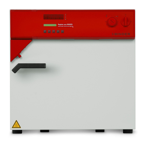
Operating Manual
FP – Drying and heating ovens
with forced convection and program functions
with microprocessor program controller RD3
Model
FP 53 (E1.1)
FP 53-UL (E1.1)
FP 115 (E1.1)
FP 115-UL (E1.1)
FP 240 (E1.1)
FP 240-UL (E1.1)
FP 400 (E1.1)
FP 400-UL (E1.1)
FP 720 (E1.1)
FP 720-UL (E1.1)
BINDER GmbH
Address: Post office box 102, 78502 Tuttlingen, Germany Phone: +49 7462 2005 0
Fax: +49 7462 2005 100 Internet: http://www.binder-world.com
E-mail: info@binder-world.com Service Hotline: +49 7462 2005 555
Service Fax: +49 7462 2005 93 555 Service E-Mail: service@binder-world.com
Service Hotline USA: +1 866 885 9794 or +1 631 224 4340 x3
Service Hotline Asia Pacific: +852 390 705 04 or +852 390 705 03
Service Hotline Russia and CIS: +7 495 988 15 16
Issue 07/2017
Model version
FP053-230V
FP053UL-120V
FP115-230V
FP115UL-120V
FP240-230V
FP240UL-120V
FP400-230V
FP400UL-120V
FP720-230V
FP720UL-120V
Art. No.
9010-0153, 9110-0153
9010-0175, 9110-0175
9010-0255, 9110-0255
9010-0262, 9110-0262
9010-0263, 9110-0263
9010-0264, 9110-0264
9010-0265, 9110-0265
9010-0266, 9110-0266
9010-0267, 9110-0267
9010-0268, 9110-0268
Art. No. 7001-0130
Advertisement
Table of Contents


Need help?
Do you have a question about the FP 53 and is the answer not in the manual?
Questions and answers