Table of Contents
Advertisement
Quick Links
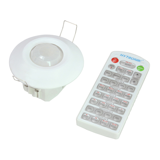
Installation and Instruction Manual
FLUSH MOUNT PIR DALI SENSOR
1. Technical Specifications
Product type
Tri-level control PIR DALI sensor
Operating voltage
9.5 ~ 22.5VDC ( suitable DALI power supply)
Input current
< 8mA
Power consumption
< 0.5W
o
Detection angle
360
Detection area (Max.)*
Installation Height : 5m
Detection Range (Ø) :10m
Detection range
10% / 50% / 75% / 100%
Hold time
2s / 30s / 1min / 5min / 10min / 15min / 20min / 30min
Stand-by time
0s / 10s / 1min / 5min / 10min / 30min / 1h / +∞
Stand-by dimming level
10% / 20% / 30% / 50%
Daylight threshold
2Lux / 10Lux / 50Lux / Disable
Warmming-up time
30s
o
o
Operating temperature
-20
C ~ +50
C
2. Installation
Warnings:
1. Installation of the sensor involves connecting it to the mains supply. This work must be
carried out by a specialist in accordance with electrotechnical regulations.
2. Disconnect supply before installing.
70mm
4
3
Photocell
(1) Sensor inset
PIR
1
(2) Lens pluggable
Infrared receiver
LED indicator
(3) Protection cover (covers the
high-voltage terminals, and leaves
the DALI terminals exposed).
Rotary switch preset
DALI group selection
(4) Ceiling (drill hole O 70mm).
2
A
B
Note1: the blinds are optional, they may be inserted
behind the lens for focussing the detection range.
Note2:We recommend the mounting distance between sensor to sensor
should be more than 2m to prevent sensors from false-triggering.
3. Rotary Switch Settings
A rotary switch is built inside the sensor for
scene selection / fast programming. Total
16 channels available:
Detection
Hold
Stand-by
Stand-by
Channel
range
time
time
dimming level
0
100%
5s
10s
10%
1
100%
1min
5min
10%
2
100%
5min
10min
10%
3
100%
5min
30min
10%
4
100%
5min
0s
Disable
5
100%
5min
+∞
10%
6
100%
5min
+∞
30%
7
100%
10min
10min
10%
8
100%
10min
30min
10%
9
100%
10min
+∞
10%
A
100%
10min
+∞
30%
B
75%
10min
+∞
10%
C
50%
10min
+∞
10%
D
100%
30min
+∞
10%
E
100%
30min
+∞
30%
F
100%
5s
10s
10%
Note: settings can also be changed by remote control HRC-11. The last action controls.
4. DALI group selection
DALI group configuration can be done on PC or on the rotary switch:
1. There are 16 channels available on the rotary switch. "0" is
for DALI broadcast, the rest 15 channels is for end user to
define the application unit.
2. PC grouping can overwrite rotary switch grouping, the last
setting controls.
3. The rotary switch channel is corresponding to the groups
DALI group selection (Please
listed below:
see the location in 2. Installation)
Switch channel
DALI group
Switch channel
0
broadcast
8
1
group 0
9
2
group 1
A
3
group 2
B
Blind
4
group 3
C
Blind
5
group 4
D
6
group 5
E
7
group 6
F
HIR23-20230717-A1
5. Functions
This DALI sensor is designed for incoporated in the DALI system, taking command from the DALI master, accepting and carrying out the grouping work with up to 64 lumanaires. It can switch on/off, or dim the
assigned group members and feed back the status to the DALI master.
HIR23
5.1 Tri-level Control (Corridor Function)
Hytronik builds this function inside the motion sensor to achieve tri-level control, for some areas require a light change notice before switch-off.
It offers 3 levels of light: 100%-->dimmed light-->off; and 2 periods of selectable waiting time: motion hold-time and stand-by period; Selectable daylight threshold and freedom of detection area.
5.2 Synchronization Function
Rotary switch preset (Please
see the location in 2. Installation)
By connecting the DALI terminals in parallel (see wiring diagram), no matter which sensor detects motion, all HMW23 in the group will turn on the lights when surrounding natural light is below the daylight
threshold. The sensor antenna is shared and the detection area could be widely enlarged in this way.
Daylight
threshold
Disable
6. Wiring Diagram
2Lux
10Lux
30Lux
10Lux
L
30Lux
N
Disable
2Lux
10Lux
30Lux
Disable
30Lux
DALI power
10Lux
supply
50Lux
Disable
2Lux
DALI
DALI
7.
Detection Pattern
DALI group
3m
group 7
group 8
group 9
group 10
Radial movement 8m
Tangential movement 10m
group 11
group 12
group 13
group 14
DALI 1
DALI 2
DALI
driver
DALI
driver
Bus-mastering
DALI master
1
50% blind A
3m
Radial movement 4m
Tangential movement 5m
DALI 1
DALI 2
HIR23
HIR23
7
corridor blind B
3m
Tangential movement 10m
HIR23-20230717-A1
Advertisement
Table of Contents

Subscribe to Our Youtube Channel
Related Manuals for Hytronik HIR23


Summary of Contents for Hytronik HIR23
- Page 1 3. Rotary Switch Settings Hytronik builds this function inside the motion sensor to achieve tri-level control, for some areas require a light change notice before switch-off. It offers 3 levels of light: 100%-->dimmed light-->off; and 2 periods of selectable waiting time: motion hold-time and stand-by period; Selectable daylight threshold and freedom of detection area.
- Page 2 Exp 2 development. Dual tech & RF mode Learn This key is not appliable on this product. Erase This key is not appliable on this product. Transmit This key is not appliable on this product. HF+PIR HF/ PIR HIR23-20230717-A1 HIR23-20230717-A1...
Need help?
Do you have a question about the HIR23 and is the answer not in the manual?
Questions and answers