Table of Contents
Advertisement
Quick Links
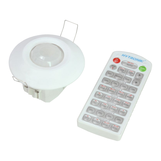
Flush Mount PIR Motion Sensor
HIR24
Daylight Harvest for Independent DALI
Mechanical Structure
70mm
4
3
1
Infrared receiver
2
Note1: the blinds are optional, they may be inserted behind the lens for focussing the detection range.
Note2:We recommend the mounting distance between sensor to sensor should be more than 2m to prevent sensors
from false-triggering.
Technical Data
Input Characteristics
Operating voltage
Stand-by power
Switched power
Warming-up
Safety and EMC
EMC standard (EMC)
Safety standard (LVD)
Certi cation
Subject to change without notice.
PIR
64.7
(1) Sensor inset
(2) Lens pluggable
(3) Protection cover (covers the
Photocell
high-voltage terminals).
LED indicator
(4) Ceiling (drill hole
PIR
220~240VAC 50/60Hz
<1W
Max. 20pcs devices, 40mA
30s
EN55015, EN61000
EN60669-1, EN60669-2-1
Semko, CB, CE , EMC, LVD, RCM
Ø
70mm).
A
Blind
B
Blind
Sensor Data
Sensor principle
Detection range
Detection angle
Mounting height
Environment
Operation temperature
IP rating
Edition: 11 Aug. 2023
IP20
Intelligent
Photocell
TX
0
5
Ambient daylight
Rotary Switch
synchronization
Programing
control
3
PIR detection
(O x H) 10m x 3m
360
O
5m (maximum)
O
O
Ta: -20
C ~ +50
C
IP20
Ver. A0
Page 1/5
One-Key
Commissioning
threshold
Advertisement
Table of Contents

Subscribe to Our Youtube Channel
Related Manuals for Hytronik HIR24


Summary of Contents for Hytronik HIR24
- Page 1 Flush Mount PIR Motion Sensor HIR24 IP20 Daylight Harvest for Independent DALI Mechanical Structure 64.7 70mm (1) Sensor inset (2) Lens pluggable (3) Protection cover (covers the Photocell high-voltage terminals). Infrared receiver LED indicator Ø (4) Ceiling (drill hole 70mm).
- Page 2 Synchronisation Function By connecting the “SYNC” terminals in parallel (see wiring diagram), no matter which sensor detects motion, all HIR24 in the group will turn on the lights when surrounding natural light is below the daylight threshold. The detection area could be widely enlarged in this way.
- Page 3 30min 400Lux 100% 100Lux Wiring Diagram P N L P N L P N L DALI driver DALI driver DALI driver HIR24 HIR24 HIR24 DALI DALI DALI Subject to change without notice. Edition: 11 Aug. 2023 Ver. A0 Page 3/5...
- Page 4 Settings (Remote Control HRC-11) Press button “ON/OFF” to select permanent ON or permanent OFF mode. * Press button “AUTO”/ “RESET” to exit this mode. Press button “RESET”, perform DIP Switch/Rotary Switch settings. *The default settings are: Detection range 100%; Hold-time 5min; Stand-by time +∞; Stand-by dimming level 10%;...
- Page 5 Additional Information / Documents 1. Regarding precautions for PIR sensor installation and operation, please kindly refer to www.hytronik.com/download ->knowledge ->PIR Sensors - Precautions for Product Installation and Operation 2. Regarding Hytronik standard guarantee policy, please refer to www.hytronik.com/download ->knowledge ->Hytronik Standard Guarantee Policy Subject to change without notice.
Need help?
Do you have a question about the HIR24 and is the answer not in the manual?
Questions and answers