Table of Contents
Advertisement
Quick Links
QUICK TOUCH TO LATCH
ELECTRONIC SWITCH ACTION
HOLD FOR MOMENTARY
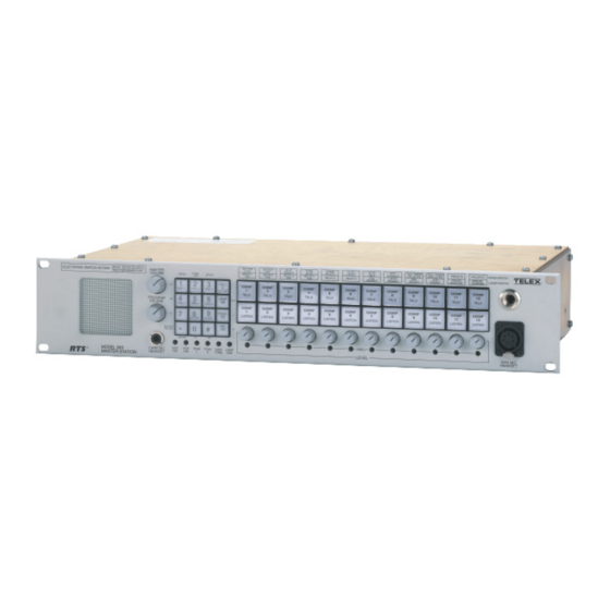
MODEL 803
TM
MASTER STATION
(Shown with Optional Panel Microphone)
9350-7547-000 Rev A1, 8 /21/97
USER INSTRUCTIONS
MODEL 803
MASTER INTERCOM STATION
BUTTON
LOCK
MASTER
RELAY 1
LOCAL
VOLUME
2W/4W
SP/L/R
IFB
IPM
CALL
1
2
3
CONF
2W
&
SETUP
1
PRESET 1
PRESET 2 PRESET 3
TALK
SPKR
PROGRAM
4
5
6
4W
SPK
ON
VOLUME
PRESET 4
PRESET 5
PRESET 6
CONF
MICS
1
PANEL
7
8
9
LISTEN
NL
L
ON
OFF
G RST
MIC
0
#
BUFFER
*
ON
R
RECALL
ISO/4W
P1
P2
1
CARB MIC
VOX
VOX
PGM
PGM
SIDE
LAMP
PM
HM
1
2
TONE
DIM
HEADSET
Model 803 Master Intercom Station
INSTANT
BILAT
TOTAL
CHIME
AUTO
AUTO
MIC
SELECT
MUTE
SELECT
LISTEN
TALK
RELAY 2
RELAY 3
RELAY 4
CALL
RELAY 5
RELAY 6
XPM
IHM
XHM
DISABLE
CONF
CONF
CONF
CONF
CONF
CONF
2
3
4
5
6
7
TALK
TALK
TALK
TALK
TALK
TALK
CONF
CONF
CONF
CONF
CONF
CONF
2
3
4
5
6
7
LISTEN
LISTEN
LISTEN
LISTEN
LISTEN
LISTEN
NULL
2
3
4
5
6
7
LEVEL
™
EXT
TALK TURNS
TALK TURNS
PRESETS
CALLER ID
UPPER SWITCH
CONTACT
ON LISTEN
OFF LISTEN
LATCH
MIC
VOX
PRESET
SPECIAL
LOWER SWITCH
DISABLE
SELECT
ENABLE
EXCLUDE
PURPOSE
CONF
CONF
CONF
CONF
CONF
8
9
10
11
12
TALK
TALK
TALK
TALK
TALK
CONF
CONF
CONF
CONF
CONF
8
9
10
11
12
LISTEN
LISTEN
LISTEN
LISTEN
LISTEN
8
9
10
11
12
DYN-MIC
HEADSET
®
Advertisement
Table of Contents

Related Manuals for RTS 803


Summary of Contents for RTS 803
- Page 1 MASTER HOLD FOR MOMENTARY VOLUME PROGRAM VOLUME BUFFER RECALL CARB MIC MODEL 803 HEADSET MASTER STATION Model 803 Master Intercom Station (Shown with Optional Panel Microphone) 9350-7547-000 Rev A1, 8 /21/97 MODEL 803 BUTTON INSTANT BILAT TOTAL CHIME LOCK SELECT...
-
Page 2: Proprietary Notice
Inc. to be free from defects in materials and workmanship for a period of three years from the date of sale. The sole obligation of Telex during the warranty period is to provide, without charge, parts and labor necessary to remedy covered defects appearing in products returned prepaid to Telex. -
Page 3: Table Of Contents
1.1.3 Setup Mode Description 7 1.1.3.1 Names for Setup Mode Features 7 1.1.3.2 Setup Mode Features 7 1.1.4 803 Compatibility with RTS Video ISO System 9 1.1.5 803 Compatibility with RTS Model 4000 IFB System and Local IFB 10 1.1.6 Comparison of 803 and 802 10 1.1.6.1 Retained Features 10... - Page 4 3.4.13 G-RST (Global Reset) 46 3.4.14 IHM (Internal Headset Microphone) Setup 47 3.4.15 INSTANT MIC Setup 3.4.16 IPM Setup 47 3.4.17 ISO/4W Setup 47 3.4.18 L Setup 47 3.4.19 LATCH DISABLE Setup 47 3.4.20 LOCAL IFB Setup 47 3.4.21 MIC SELECT Setup 48 3.4.22 MICS OFF 48 3.4.23...
-
Page 5: Description And Specifications
For all other applica- tions, everything you need is "in the box". In terms of form, fit and function the 803 can directly re- place the 802 with the following exceptions: 1) squawk is not supported on the 803;... -
Page 6: Controls, Indicators, Connectors
1.1.2 803 Controls, Indicators, Connectors 1.1.2.1 Front Panel, User Controls 1 Master volume control. 1 Program master volume control. 12 intercom channel level controls. 16-button keypad with backlit, user-replaceable la- bels ; the keypad operates in normal, setup and DTMF modes; normal and DTMF mode labeling is printed on the button labels in normal text;... -
Page 7: Internal Dip Switches And Jumpers
801 emulation: Default: 801 emulation disabled. Internal/external ISO select: internal is used when the 803 emulates a VCP panel; external is used when the 803 connects to an external VCP panel, or when ISO is not used. Default: external. - Page 8 The microphone also activates, so that the 803 user can talk to the caller with- out having to press any buttons. Default setting: auto talk disabled for all channels.
-
Page 9: Compatibility With Rts Video Iso System
VCP panel causes deactivation of all conference chan- nel talk buttons at the 803 (listen button deactivation may also be setup via an internal 803 DIP switch), and the 803 mic audio is automatically routed to the VCP system. -
Page 10: Compatibility With Rts Model 4000 Ifb System And Local Ifb
803 Compatibility with RTS Model 4000 IFB System and Local IFB The 803 can be connected to an external 4001 or 4002 IFB Panel. For external IFB, button activation at the IFB panel causes deactivation of all conference channel talk buttons at the 803, and the 803 mic audio is automatically routed to the IFB system. -
Page 11: Specifications
Data bits: 8 Stop bits: 1 Parity: none Handshaking: none * Initial connection at 2400 baud required. After connect- ing the 803 may be set to 300, 600, 1200, 2400, 4800, or 9600 baud. Environmental Ambient Temperature Storage: -40°C to +85°C Operating: 0°C to 50°C... - Page 12 Input Frequency: 47 Hz to 63 Hz Inrush Current, Cold: 15 A @115 VAC, 30 A @230 VAC Outputs Power, Nominal: 43 VA Supplies +5 VDC,3A +15 VDC, 1.6 A -15 VDC, 0.3 A Line regulation: +0.2% Load regulation +5 VDC: +/-3% +15 VDC: +/-5% -15 VDC: +/-10% Ripple &...
-
Page 13: Installation
Refer to Table 1 for the items included with your 803. If anything appears missing or damaged, con- tact your dealer. If your 803 includes option cables, proceed to "Option Ca- ble Installation" on the next page. Otherwise, skip to "DIP Switch Settings", page 16. -
Page 14: Option Cable Installation
Option Cable Installation 2.2.1 General Information The connector openings for the option cables are labeled on the back panel as follows: ISO 1 Connector: Used for VCP-6 and VCP-12 ISO Panel Emulation; provides connections for ISO1 through ISO6. IFB 1 Connector: Used for 4001 and 4002 IFB Panel Emulation;... -
Page 15: Ifb 1 Cable Notes
When you install an IFB or ISO option cable and set the internal DIP switches as noted in the following para- graphs, specific front panel buttons will be reserved for the installed option. The button insert sheet provides standard button labels for these reserved buttons. See "Front Panel Button Inserts", page 17 for details. -
Page 16: Dip Switch Settings
DIP Switch Settings Unless you are using the 803 for IFB or ISO operations, you will probably not need to change any of the DIP switch settings. However, briefly review the tables below and make any required or optional changes before pro- ceeding. -
Page 17: Led "Off" Brightness Jumpers
(The setup mode features are described starting on page 43.) Key code switch settings are as follows: 0: No access permitted (no one can program the 803) 1-9: User must enter this number before accessing setup mode A-F: No restrictions on access to setup mode (default) Note: The key code switch has a stop at the 0 setting. - Page 18 IFB 1 AND ISO 1 CONNECTORS INSTALLED 6 CONFERENCE LINES; 6 BUTTONS EMULATE A MODEL 4001 IFB PANEL 6 BUTTONS EMULATE A MODEL VCP-6 ISO PANEL Figure 7. Button usage for various configurations of the 803 CONF CONF CONF CONF CONF CONF...
-
Page 19: Resetting The 803
43) could erase your programmed settings. The 803 has two reset modes: cold reset and warm reset. A cold reset restarts the 803 and erases all setup mode pro- gramming. All front panel buttons are turned off (except the SPK ON button, which always starts up in the on posi- tion). -
Page 20: Mounting The 803
Note: If the mounting location for the 803 provides access to the back panel controls and connectors, you should be able to mount the 803 at this time. Otherwise, perform the connections and adjustments as described in the following sections before mounting the 803. -
Page 21: J101 Connector
If you are connecting a powered channel, termination is usually accomplished by the power supply. The 803 has built-in dc isolation, and so it is not neces- sary to use isolation capacitors when connecting to a pow- ered intercom channel. -
Page 22: J102 Connector
The two com- mon connections for each relay are electrically identical. All relay connections are electrically isolated from the rest of the 803 circuitry. Relay connections are also avail- able at J108, page 28. External Switch Contact Input (XSW) A switch may be connected between pins 13 and 38 for re- mote operation of a front panel button. -
Page 23: J103 Connector
2.9.3 J103 Connector J103 is an optional connector provided when the IFB 1 op- tion is installed. Typical applications of this connector are shown in Figure 18, page 38 and Figure 20, page 40. Table 6. J103 connector pin-out Description IFB button #1 IFB button #2 IFB button #3... -
Page 24: J104 Connector
2.9.4 J104 Connector J104 is an optional connector provided when the IFB 2 connector is installed. A typical application of this connec- tor is shown in Figure 18, page 38. Table 7. J104 connector pin-out for IFB usage (see Table 8 for ISO usage) Description IFB button #5 IFB button #6... -
Page 25: J104A Connector
2.9.5 J104A Connector J104A is an optional connector provided when the ISO 2 connector is installed. A typical application of this connec- tor is shown in Figure 19, page 39. Table 8. J104A connector pin-out for ISO usage Description ISO button #7 ISO button #8 ISO button #9 ISO button #10... -
Page 26: J105 Connector
2.9.6 J105 Connector J105 is an optional connector provided when the 4-wire connector is installed. A typical application of this connec- tor is shown in Figure 21, page 41. Table 9. J105 connector pin-out Description 4-Wire Listen Low 1 (4WLL1) 4-Wire Listen High 1 (4WLH1) 4-Wire Listen Low 2 (4WLL2) 4-Wire Listen High 2 (4WLH2) -
Page 27: J106 Connector
2.9.7 J106 Connector J106 is an optional connector provided when the ISO 1 connector is installed. Typical applications of this connec- tor are shown in Figure 20, page 40 and Figure 19, page 39. Table 10. J106 connector pin-out Description ISO button #1 ISO button #2 ISO button #3... -
Page 28: J108 Connector
ISO system. To connect external ISO: Connect J108, pin 13 of the 803 to TB2, pin 2 of the VCP; connect J108, pin 25 to TB2, pin 3. This is the audio output connection from the 803 to the VCP. -
Page 29: J109 Connector
2.9.9 J109 Connector J109 can be used to connect to a computer or terminal for remote access and control of the 803. Use a standard RS232 cable (not null modem). Default RS232 port set- tings are 2400 baud*, 8 data bits, 1 stop bit and no parity. - Page 30 Table 13. Examples of commands and responses Description ......Command Sequence . . . 803 Response Turn button 12 on: .
-
Page 31: J110 Connector
Error Handling for the RS232 and RS485 Ports Upon detection of an error in a command, the 803 will typically ignore the command and send out an error mes- sage consisting of the letter E along with a 2 digit code as... -
Page 32: J111 Connector
The output cannot be muted on the standard 803 model. 2.9.12 J112 Connector J112 is intended for use with the external 803 power supply. Table 14. J111 connector pin-out Description Dynamic mic ground... -
Page 33: J201 Connector
To change this, see "Mic Select Setup", page 48. The IHM gain is adjusted via the IHM trimmer on the back panel. The standard 803 uses a 5-pin connector for J202. This connector is used for headsets without a mic switch. -
Page 34: Miscellaneous Connections
Connect the intercom channel to the remote listener's station. When connecting both local IFB channels and standard intercom channels to the 803, it may be convenient to use splitters. An example for 2-wire ap- plications is shown in Figure 22, page 42. For a 2- wire IFB channel, use the appropriate pins at the J101 connector, page 21. - Page 35 MRT-327 intercom stations conference on channel 1. Channel 2 of each intercom station communicates with the 803 on a private channel. The PS-31 provides power to the intercom stations on channel 1 and also provides the 200-ohm line termination for this channel. The 4012 provides a separate 200-ohm line termination for each of the twelve channels of the 803 that communicate separately with each intercom station.
- Page 36 (channel 1 or channel 4). This channel is not available to the 803's. Each 803, however can selectively communicate with any of the 4 in- tercom branches on a private channel.
- Page 37 Figure 17. A balanced, 2-wire intercom system using only 803 intercom stations. Each intercom station can talk and listen to any one or combination of intercom stations. A 200-ohm resistor is connected across each 2-wire channel to set the terminating impedance. By adding another 4025A interconnect panel, the system could be ex- panded to 12 stations.
- Page 38 Talent 7 Figure 18. IFB panel emulation with 803 Master Stations. In this example, the 803 stations are equipped with op- tional IFB1 and IFB2 connectors. Twelve front panel buttons emulate a Model 4002 IFB panel. Each 803 may send IFB selectively to any of the 8 talent locations or to all 4 talent stations on each 4010, or to all 8 talent stations.
- Page 39 Figure 19. ISO panel emulation with 803 Master Stations. In this example, the 803 stations are equipped with op- tional ISO1 and ISO2 connectors. Twelve front panel buttons emulate a Model VCP-12 ISO panel. Each 803 may selectively ISO any of the twelve cameras. Note that in this configuration, channels 1 through 6 are still available for use as 2- or 4-wire intercom channels.
- Page 40 IFB1 and ISO1 connectors. Six front panel buttons emulate a Model 4001 IFB panel, and six emulate a VCP-6 ISO panel. Each 803 may send IFB selectively to any of the 4 talent locations or to the stage announce output of the 4010.
- Page 41 J101 and J105. In this application, the 4-wire talk outputs are connected using J101. The only rea- son for doing this is to also provide access to the keying outputs of the 803. For example, it may be necessary to key a radio transmitter when talking to it.
- Page 42 Figure 22. Using splitters with 2-wire channels to provide 6 regular intercom channels and 6 local IFB channels. 4022 803-C PS-31 4012 BP325 BP325 BP325 BP325 BP325 BP325 4024 To 2-wire Local IFB circuits using 803 channels 7-12. 803 Channels 1 to 6...
-
Page 43: Setup Mode
Setup Mode Introduction Setup mode lets you access almost all of the programma- ble features of the 803 using the front panel buttons. This section describes each of these features. Reminder: Changing certain internal DIP switch settings (the ones that are grayed-out in Tables 2 and 3 on page 16) will erase all user programming that you configured in setup mode. -
Page 44: Setup
The MIC ON button also activates, so that the 803 user can talk to the caller with- out having to press any buttons. Default setting: off for all channels. -
Page 45: Buffer Recall Setup
To quit setup mode tap the CALL & SETUP button. Note that you must quit, then re-enter setup to assign additional unused channels. 3.4.7 BUFFER RECALL Setup Buffer recall is a convenient way to assign the current on/off settings for all talk and listen buttons to any one of the PRE 1 through PRE 6 preset buttons. -
Page 46: Call Disable Setup
CALL DISABLE Setup 3.4.9 This feature disables or enables call signal reception on se- lected channels. When call signal reception is disabled on a channel, there will be no chime tone or button flash to indicate an incoming call. Outgoing call signals are not af- fected. -
Page 47: Local Ifb Setup
IFB channel normally sends a program feed to a re- mote listener. By pressing the talk button for the local IFB channel, the 803 station operator can interrupt the pro- gram feed and then talk to the remote listener. If the IFB channel is configured as a 2-wire channel, either the pro- gram 1 or 2 input can be selected as the program source. - Page 48 *, 0, and # buttons will then display the program source being used with that button. 3.4.21 MIC SELECT Setup This feature selects which microphone inputs are acti- vated by the PANEL ON button in both the on and off po- sitions.
-
Page 49: Relay 1 Through Relay 6 Setup
Enter setup mode (page 43). Tap the PRESETS button (TALK 11). The PRE 1 through PRE 6 preset buttons on the key- pad will start flashing. Tap any one of these buttons to select it. Talk and listen buttons that are currently assigned to that preset button will flash brightly. -
Page 50: Talk Turns On Listen Setup
Tap CALL & SETUP to exit. 3.4.36 VOX ENABLE Setup The 803 can be set for voice-activated microphone. When this feature is enabled the microphone will remain off when you are not speaking into it. When you do speak, the microphone will turn on, and your voice will be trans- mitted on any channels that have talk buttons activated. -
Page 51: Adjustments
ON-MIC HEADSET connector. PM (Internal Panel Microphone) This trimmer adjusts the gain for a panel microphone con- nected at the front panel of the 803. EXT HM (External Headset Microphone) This trimmer adjusts the microphone gain for a dynamic- or carbon-mic headset connected at J111. -
Page 52: Sidetone Adjustment
Repeat the adjustment for each remaining channel that is being operated in 2-wire mode. This completes the null adjustment. If you will be using headphones with the 803, perform the sidetone adjust- ment after the null adjustment. 4.2.5 Sidetone Adjustment The sidetone adjustment lets you set the level of your own voice in the headphones when using a headset. -
Page 53: Intercom Operation
Intercom Operation Initial Volume Adjustment Prior to first use, set the MASTER VOLUME and PRO- GRAM VOLUME controls to the minimum position. Set the twelve channel LEVEL controls to about the half-on position. Later, you can adjust the individual channel lev- els up or down to balance channels that are unusually loud or soft. -
Page 54: Sending Call Signals
The 803 is capable of generating DTMF tones for dialing out on a phone line. If there is a telephone interface con- nected on an intercom channel, you can use the 803 key- pad to dial out on that channel. The actual method that... -
Page 55: Iso Operation Using An External Vcp Panel
ISO operation. When you are using the 803 in VCP emulate mode, you can use the global reset feature of the 803 to shut off all ISO buttons in the system. To do this, tap the G-RST button on the 803 keypad. -
Page 56: Index
Keying Outputs Control codes for RS232/RS485 port 30 J101 connections 21 Number available 5 Specifications 11 Typical connection 34 Using a breakout panel with 41 Labels Buttons, general information 6 Setup mode 7 Model 802 Compared to Model 803 5, 10... - Page 57 On front panel 6 Two-Wire 2W/4W Setup 43 Button insets used with 17 General information 5 Interconnecting 803's in 2-wire mode 37 J101 connections 21 Null adjustment 51 Related to 4-wire connections 26 Specifications 11 Usage with local IFB 34, 47...
Need help?
Do you have a question about the 803 and is the answer not in the manual?
Questions and answers