RTS RVON-I/O User Manual
Digital matrix series
Hide thumbs
Also See for RVON-I/O:
- Release notes (8 pages) ,
- Specification sheet (2 pages) ,
- User manual (80 pages)
Table of Contents
Advertisement
Advertisement
Table of Contents

Related Manuals for RTS RVON-I/O


Summary of Contents for RTS RVON-I/O
- Page 1 RVON-I/O User Manual 9350-7772-000 Rev F 12/2006...
- Page 2 COPYRIGHT NOTICE Copyright 2006 by Telex Communications, Inc. All rights reserved. Reproduction, in whole or in part, without prior written permission from Telex is prohibited. WARRANTY NOTICE See the enclosed warranty card for further details.
-
Page 3: Table Of Contents
Introduction ...1 Description ...1 Features ...1 Reference View ...2 Specifications ...3 Pin Outs for Connections ...4 DIP Switches ...5 Installation ...7 System Requirements ...7 Reset the Current IP Address to the Default RVON-I/O IP Address ...8 Basic Installations ...8 Basic Local Mode Setup ...9 Basic Remote Mode Setup ...9 RVON-I/O Trunk Setup ...10 RVON Serial Pass-through Setup ...11... -
Page 5: Introduction
Description Coupled with the same VOIP technology used with the RVON-8, the RVON-I/O can take legacy analog audio and convert it to digital VOIP audio. The RVON-I/O expands the boundaries of digital audio to include analog conversion. There are many applications in which the RVON-I/O can be used, such as: •... -
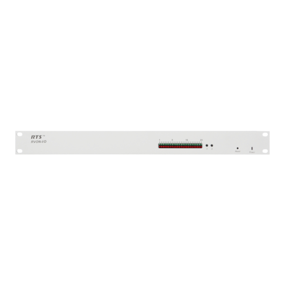
Page 6: Reference View
(this only applies to LEDs 23-16). Fail LED - Power ON and OFF/ AC Power Plug 90 - 240 VAC TELEX ® TELEX COMMUNICATIONS, INC. MADE IN U.S.A. Resets the device Reset Power LED indicator displays green when device is... -
Page 7: Specifications
Specifications Specifications Connections RJ-45 Ethernet DB-9 I/O Port (8 bidirectional audio and keypanel data; Male) DB-25 GPI/O Connection (Female) DB-9 Relay Port (Female) DB-9 Serial Port Power 90-240 VAC Physical 1 RU (height) 19 inches (482.6 mm) wide X 8 inches (203.2 mm) deep Digital Digital Specifications TABLE 1. -
Page 8: Pin Outs For Connections
Introduction Pin Outs for Connections RJ-45 Pin Function Ethernet Ethernet TPO+ Ethernet TPO- Ethernet TPI+ TPO+ TPO- Ethernet TPI- TPI+ TPI- DB-9 Pin Function I/O RS485+ RS485- RVON-I/O Audio IN+ RVON-I/O Audio IN- RVON-I/O Audio OUT- RVON-I/O Audio OUT+ See page Figure 2, “DB-9 Crossover Cable Connection Diagram,”... -
Page 9: Dip Switches
DIP Switches DIP Switches DIP Switch 1: RVON-I/O Mode Default Position: OPEN OPEN Switch Position: CLOSED - Remote Mode There are two modes in which the RVON-I/O can run: LOCAL and REMOTE mode In LOCAL mode, keypanels are directly connected to the RVON-I/O. For example, a KP-32 is connected serially to the RVON-I/O which is connected via Ethernet to the RVON-8 in the ADAM system. - Page 10 Introduction DB-9 Crossover Cable Connection Diagram Optional: On the ADAM CS and the Zeus, connect pins 3, 6, and 9 to sheild. DB-9 Crossover Cable Connection Diagram FIGURE 2. RJ-12 to DB-9 Crossover Cable Connection Diagram DB-9 F RJ-12 To RVON-I/O To Matrix RJ-12 to DB-9 Crossover Cable Connection Diagram FIGURE 3.
-
Page 11: Installation
The RVON-I/O can operate in one of two modes, LOCAL mode or REMOTE mode. When operating in LOCAL mode, key- panels are directly connected to the RVON-I/O. For example, a KP-32 is connected serially to the RVON-I/O, which is con- nected via Ethernet to the RVON-8. -
Page 12: Reset The Current Ip Address To The Default Rvon-I/O Ip Address
Installation Reset the Current IP Address to the Default RVON-I/O IP Address The RVON-I/O is shipped with a default IP Address already configured on the unit. The default IP Address is 192.168.0.1, the default Netmask is 255.255.0.0, the default Gateway is set to zero. This feature is useful when using an RVON-I/O in the field (i.e.;... -
Page 13: Basic Local Mode Setup
In LOCAL mode, the keypanel is directly connected to the RVON-I/O through the use of a DB-9 serial cable. To setup an RVON-IO local mode system, do the following On the back of the RVON-I/O, put DIP switch 1 in the OPEN position (LOCAL mode). -
Page 14: Rvon-I/O Trunk Setup
Installation Once you are finished configuring the RVON-I/O, type ACTIVATE into the command prompt to activate the configuration setup on the RVON-I/O. NOTE: If you do not have a RVON-1 pre-installed, the KP-32 or the KP-812 must have the RVON-1 component installed prior to Remote setup (See the RVON-1 User Manual for details). -
Page 15: Rvon Serial Pass-Through Setup
RVON Serial Pass-through Setup RVON Serial Pass-through Setup The Serial Pass through is the path in which data is sent and received Verify the correct port is selected - on J1 see “Pin Outs for Connections” on page 4. Verify the serial connections are correct. Verify Pass Through Port is enabled (DIP Switch 2 OPEN), see “DIP Switches”... -
Page 16: System Diagrams
Installation System Diagrams Local Mode - This system diagram shows Local mode. It is called local mode because the keypanel is FIGURE 5. connected directly to the RVON-I/O. LAN/WAN RTS™ RVON-I/O Reset Power DB-9 Straight Cable AUTO Listen Headset MENU Talk Vol. - Page 17 System Diagrams DB-9 Crossover Cable ---- ---- ---- ---- ---- ---- ---- ---- KP12 OKP4 ANDY KP32 DAN KP96 TIF1 KP12 Headset Remote Mode - Remote Mode means the keypanels are not connected to the RVON-I/O directly. In the FIGURE 6. example, the KP-32 with RVON-1 or the VKP has to pass through the LAN/WAN before connecting to the RVON-I/ POWER RESET...
- Page 18 Installation Local and Remote Mode - The lower portion of the graphic shows a local setup (the keypanel is directly FIGURE 7. connected to the RVON-I/O), while the upper portion of the graphic shows a remote setup. The RVON-I/O works similar to an audio converter box.
- Page 19 System Diagrams Trunking with RVON-I/O - When you trunk two intercom systems together using two RVON-I/O’s, you FIGURE 8. can configure one as Remote and the other as Local. However, remote to remote setup is the preferred system setup for trunking. POWER RESET STATUS...
-
Page 20: Rvon-1 Jumpers And Connections
Installation RVON-1 Jumpers and Connections A selectable RS232/485 serial port is a connector J1. Jumper connections on J10, J11, and J12 select the signal mode on J1. • When J10, J11, and J12 are jumped from pins 1 to 2 - J1 is configured for RS485. •... -
Page 21: Configuration
Setup IP Addresses There are three ways in which the IP Address can be set on the RVON-I/O; via a keypanel, through Telnet, or using the Serial Debug Port. If you are using a keypanel to set the IP Address of the RVON-I/O, you must use a KP-32, KP-632, KP-832, or a KP-812. There are two sets of instructions to configure the IP Address from a KP-32, KP-632, KP-832 and a KP-812. -
Page 22: Configure The Ip Address From A Kp-812
Configuration NOTE: Press PGM to skip over any octet that does not need modification. Repeat steps 8 and 9 until the entire IP Address is entered. Press PGM. The Netmask menu item appears. NOTE: Once you have entered the IP Address, you will then enter the Netmask. The Netmask is a string of numbers similar to an IP Address, except that it masks or screens out the network port of an IP Address so that only the host computer part of the address remains (for example, 255.255.255.0). -
Page 23: Configure The Ip Address Using Telnet
Setup IP Addresses Tap the Select knob. The IP Address menu item appears. Tap the Select knob. The current IP Address appears. Enter the first number in the IP Address. This activates the first octet of the IP Address and clears the rest of the IP Address. Tap the Select knob. - Page 24 Figure 2. Press Enter. The RVON login screen appears. Figure 3. In the logon field, type the RVON login (default = telex). Press Enter. In the password field, type the RVON password (default = password). Press Enter. An arrow prompt appears.
-
Page 25: Configure The Ip Address Using The Serial Debug Port
Setup IP Addresses At the prompt, type dbgcmd to access the debug command screens. Figure 4. Press Enter. An MXP prompt appears. At the MXP prompt, type set rvon ip_addr 10.3.210.12 (this IP Address is for example purposes only). Press Enter. The IP Address is set for the RVON-I/O. -
Page 26: Configure The Rvon-I/O Using Telnet Or A Serial Port
Configuration At the MXP prompt, set rvon ip_addr 10.3.210.20 (this IP Address is for example purposes only). Figure 5. Press Enter. An MXP prompt appears. Press Enter. The IP Address is set for the RVON-I/O. Set the Netmask. At the MXP prompt, type Activate. RVON-I/O will reset itself to the new IP Address. - Page 27 Figure 6. Press Enter. The RVON login screen appears. Figure 7. In the login field, type the RVON login (default = telex). Press Enter. In the password field, type the RVON password (default = password). Press Enter. A prompt appears.
- Page 28 Configuration At the prompt, type dbgcmd to access the debug command screens. Figure 8. Press Enter. An MXP prompt appears.
-
Page 29: Rvon-I/O Command Table
Set the Network Mask for the RVON-I/O. X.X.X.X Set the Gateway IP Address for the RVON-I/O. Set the RVON-I/O user name for Telnet access. username Default = telex Set the RVON-I/O password for Telnet access (8-40 characters). password Default = password Set the VAD threshold (silence detection). - Page 30 Configuration RVON-I/O Command Table TABLE 9. Command Parameter 1 set serial baud set gpio set gpio mode set gpio ip_addr set gpio panel set panel set panel [pnl] poll_id set panel [pnl] baud Examples: Set RVON ip_addr to 10.3.210.12. At the command prompt, type set rvon ip_addr 10.3.210.12 Set the destination channel type to RVON-I/O.
- Page 31 RVON-I/O Command Table Codec Specifications. TABLE 10. 0,3,6,9 G.711 1,4,7,10 G.711 2,5,8,11 G.711 12,16 G.729 13,17 G.729 14,18 G.729 15,19 G.729 20,22 G.723 5.3k 24,26 G.723 6.3k 21,23 G.723 5.3k 25,27 G.723 6.3k NOTE : A channel consists of a transmitting and a receiving side, so the bandwidth is double for a bi-directional audio stream. NOTE : Bandwidth values are approximate maximums, actual bandwidth could be considerably lower with VAD enabled.
- Page 32 All are “set rvon” commands COMMAND DEFAULT VALUE ip_addr 192.168.0.1 netmask 255.255.0.0 gateway none user telex password password vad_threshold There are more parameters the software will auto-configure if they have not been previously setup. Codec Rate Size 5.3k 5.3k 5.3k 5.3k...
-
Page 33: Set Serial
RVON-I/O Command Table All are “set channel #” commands because they are for each audio channel. COMMAND DEFAULT VALUE dest_ip 0.0.0.0 dest_type dest_chan chan_codec Set Serial When using Serial Pass-Through Mode, you must set the serial port you will use with the IP Address for the destination serial pass-through port you are going to use. -
Page 34: Set Panel
Configuration 1 Keypanel Mode GPI/O assignments TABLE 13. LOCAL RVON-I/O GPI/O GPI/O HARDWARE PORT GPI/O 9 DB-25 Port 1 GPI/O 10 DB-25 Port 2 GPI/O 11 DB-25 Port 3 GPI/O 12 DB-25 Port 4 GPI/O 13 DB-25 Port 5 GPI/O 14 DB-25 Port 6 GPI/O 15 DB-25 Port 7... - Page 35 RVON-I/O Command Table RVON-I/O A RVON-I/O B If you are using Cronus or AIO-16 with RVON-I/0 in Remote mode for keypanels, you will still have to set a panel poll ID. This is because the RVON-I/O has a default panel poll ID of 0 (zero). This must be changed to a non-zero number. NOTE: Make sure to set the panel poll ID to 0 when trunking in Remote Mode.
- Page 36 Configuration...
-
Page 37: Rvon-I/O Quick Start
At the prompt, type telnet 192.168.0.1 (default RVON-I/O IP Address). The RVON login screen appears. In the logon field, type telex (default user logon for the unit). Press Enter. In the password field, enter password (default password for the unit). -
Page 38: Setting Channel Information Of An Rvon-I/O For A Remote Keypanel
Open a Telnet Session. Type telnet 192.168.0.10 (default). Press Enter. RVON login appears. Type telex, and press Enter. RVON password appears. Type password, and press Enter. At the prompt, type dbgcmd and press Enter. You have entered MXP programming shell. - Page 39 At the prompt, type telnet 192.168.0.1 (default RVON-I/O IP Address). The RVON login screen appears. In the logon field, type telex (default user logon for the unit). Press Enter. In the password field, enter password (default password for the unit).
Need help?
Do you have a question about the RVON-I/O and is the answer not in the manual?
Questions and answers