
Related Manuals for RTS 848A


Summary of Contents for RTS 848A
- Page 1 TM5545 / 9380-5545-80 Rev E Matrix Intercom Station O/N 9000-5545-00 Data Connector 81N 9000-5556-08 RTS SYSTEMS A TELEX COMMUNICATIONS PRODUCT...
- Page 2 Should there be any, notify the freight company and the dealer at once. The Model 848A Matrix Intercom Station shipping con- tainer should contain the following components: Ordering Number 9000-5545-00...
- Page 3 RTS Systems The Center at Burbank Aiiort 2550 Hollywood Way, Suite 207 Burbank, CA 9 1505 U.S.A. Telephone: (818) 566-6700 Telex: 194855 Telefax: (818) 843-7953 SHIPPING TO MANUFACTURER FOR REPAIR OR ADJUSTMENT All shipments of RTS Systems equipment should be via United Parcel Service or the best available shipper.
- Page 4 TECHNICAL MANUAL Model 848A Matrix Intercom Station TD OTHER TW INTERCOM Note: This block diagram shows a full size system with cable connections for the STATIONS (IF USED); matrix intercom signals (50-conductor cable), the Pchannel conference-line signals (3-conductor cable), and the serial data bus signals (single-pair, twin shield cable).
- Page 5 TECHNICAL MANUAL Model 848A Matrix Intercom Station Model DC848 Data Concentrator Appendix A Table A-d. Location versus Address Assignment and Cabling Page A-1...
- Page 6 ADDENDUM TO MODEL 848A/DC848 ADDENDUM 1 Model 8slSA/DC848 software update to Version 6.5 has added the following features: Dynamic Matrix Display screen: In the System Status Menu, after viewing the Dynamic Matrix Display, by hitting [return] a user may call up an additional display showing the status of the bottom-row buttons for each of the 24 panels.
- Page 7 Model 848A Matrix Intercom Station Name Cage Code BLDG. 502, POB 2 9 6 3 AUSTIN TX 78769-2963 27901 AHAM 1 4 1 4 ALLEN-BRADLEY DR, EL PAS0 TX ALLEN-BRADLEY AMATOM 4 4 6 BLAKE ST, NEW HAVEN CT 0 6 5 1 5...
- Page 8 Model $48A Matrix Intercom Station PANDUI T 1 7 3 0 1 RIDGELAND AV, TINLEY PK I L 60477-0981 PO BOX 1000, DANBORO, PENN & DANBORO, PA 19816- 1000 PENN ENG MANU FEEHANWILLE DR, MT PROPSPECT I L 6 0 0 5 6 PIHER ROBINSON NUGENT INC 8 0 0 E 8TH ST, NEU ALBANY I N 47150...
- Page 9 Model 848A Matrix Intercom Station O E M Part O E M C A G E C O D E Vendor Part No EC100F-5 8216-A-0632 9293 9475A0632 2334 95328-8-0440 95328-8-0440 95348- 8-0632 1416-6 1416-6 99-910 A4-10-501-20 3341-1L THlS4 KF2-440 EC100F-3...
- Page 10 Model 848A Matrix Intercom Station O E M Part No O E M C O D E Vendor Part No CAGE . . - 60572 ~ 1 ~ 1 6 ~ - 1 0 8 - 60572 DIL40P- 108 DS1213...
- Page 11 TECHNICAL Model 848A Matrix Intercom Station MN114B 82389 MN114B 82389 30-454 535 14 30-453 53514 AXR-5-31 71468 HA16PR-3s 0ag18 SEP- 10K8-02 55322 CE100F24-3 06383 CE100F24-5 06383 30-453 53514 AXR-5-31 71468 WP664012CG 59940 LM9003 081 16 LM9003 081 16 42TM018 5081 1...
- Page 12 Model Matrix Intercom Station 848A SECOND REVISIONS FOR THE PRINTING: Date Edition Pave No. 6/89 Cover 6/89 Cover 6/89 6/89 6/89 6-14 7-11 7-17 6/89 7-25 6/89 RTS Systems, Inc. Burbank, TECHNICAL MANUAL Model DC848 Data Concentrator Descriotion of Revision Added: Second Printing, June 1989.
- Page 13 Model programmed remotely by connecting either a computer or a "dumb" terminal to the Model DC848 data bus. The software for the 848A and DC848 lets each station be programmed individually in real-time. Features programmable with this setup include: Forced Crosspoint.
- Page 14 The program input accepts a -10 dBu signal which is distributed to both the loudspeaker and the headsets. The level can be adjusted on the adjustment card. The unswitched microphone output provides a 10 dBu line level signal from the Model 848A microphone preamplifier. Page 1-2 INTERCOM CH.l INTERCOM CH.l...
- Page 15 Any switch, such as a foortswitch, can be used to short the two terminals together to turn on the microphone circuit. Model 848A Preset (Trimpot) Adjustments 1 . 1 . 5 The preset adjustment pots are located behind the s m a l l rectangular panel to the left of the loudspeaker.
- Page 16 Model 848A Matrix Intercom Station/Model DC848 Data Concentrator 1 . 2 SPECIFICATIONS 12.1 MODEL 848A MATRIX INTERCOM SYSTEM SPECIFICATIONS Bus Complement 24 balanced distributed talk/listen buses balanced distributed all talk bus Intercom 2-wire buses Audio Level/Bus Impedance Distributed Summine Buses...
- Page 17 Model Matrix Intercom Station/Model B C 8 4 8 Data Concentrator 848A 1 . 2 . 2 MODEL 848A INTERCOM STATION SPECIFICATIONS Microphone Preamplifier Input Input Impedance Source Impedance M a x i m u m Input Level Voltage G a i n...
- Page 18 Model 84814 Matrix Intercom Station/Model DC848 Data Concentrator MODEL 848A INTERCOM STATION SPECIFICATIONS (Continued) 1 . 2 . 2 Auxiliary Connections External Headset External Panel Microphone External Electret Panel Mic External Microphone On--Off @-lo Unswitched Mic Output Program Input @-I0 dBu, 10K ohms...
- Page 19 Remote terminal to emulate DEC VTlOO or equivalent. Settings: 9600/4800/2400/1200/600/300 baud, software selected, 8 bits, 1 start bit, 1 stop bit, no parity. Connection to string of Model 848A stations: 5102/5103: RS422, Parameters RS485 half duplex serial communication network 78.6 kilobaud, 8 bits, 1 start, 1 stop bit.
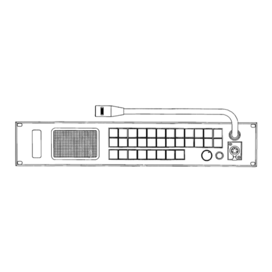
- Page 20 TECHNICAL MANUAL Model 84814 Matrix Intercom Station/Model DC848 Data Concentrator Figure Model 848A Rear Panel Page 1-8...
- Page 21 2.1 INSTALLATION PROCEDURE TECHNICAL MANUAL Intercom Station Model DC848 Data Concentrator connectors on the back of the Model 848A are labeled JlOOl and 51002, and wired i n parallel. The data connectors on the back of DC848 are the Model...
- Page 22 TECHNICAL MANUAL Model 848A Matrix Intercom Station / Model DC848 Data Concentrator Table 2-1 Matrix Audio Cables, Splitters, and Termination Plugs Required Page 2-2...
- Page 24 TECHNICAL MANUAL Model 848A Matrix Intercom Station /Model DC848 Data Concentrator Table 2-3 Conference Audio Cables, Splitters, and Termination Plugs Required Page...
- Page 25 TECHNICAL MANUAL Model 848A Matrix Intercom Station Model DC848 Data Concentrator Table 2-4 Location versus Address Assignment and Cabling Log Page 2-5...
- Page 26 TECHNICAL MANUAL Model 848A M a t r i x Intercom Station Model DC848 Data Concentrator Table 2-5 Station Select Logical Address: Dip Switch Setting Chart Page 2-6...
- Page 27 2 3 . 2 . 2 . 1 Listen Bus Selection (Audio) Back Panel Jum~ers The Model 848A back panel, which sets the listen bus. On the Model 848A, it is not necessary to use the back panel programming section to inhibit a station from Page 2-7 .Gnd .Shield...
- Page 28 Model 848A Matrix Intercom Station /Model DC848 Data Concentrator calling other stations as was necessary on the Model The Model 848A must be assigned its own station listen bus by using jumpers. One of these jumpers connects a pin in row C to the corresponding pin in row D; the other jumper connects a pin in row E to the corresponding pin in row F.
- Page 29 Model 848A Matrix Intercom Station Remote Micro~hone Switching There are two ways to switch a remote microphone: Through the rear panel Mic switch, or via a phantom connection through the dynamic headset connector. Rear Panel Microphone Switch: A remote footswitch or other dry contact may be connected to the auxiliary connector through pins 6 and 7.
- Page 30 Model 848A Matrix Intercom Station /Model DC848 Data Concentrator MODEL DC848 SERIAL FORMAT The RS232C serial format for the Model DC848 Data Concentrator is: baud, 8 bits, 1 start bit, 1 stop bit, no parity. A terminal must emulate DEC's (Digital Equipment Cor- poration) VT100-type terminal for the proper escape se- quences and control characters used by the DC848.
- Page 31 When set, the loudspeaker will automatically whenever a call is received. Tallv Flash Time When a call is received at an 848A station, the pushbutton corresponding to the calling station will flash (if the talk path is not already on), providing a tally that tells the responding operator where the incoming call originated.
- Page 32 The Panel Switch Action Menu (Latch Disable): On the PANEL SWITCH ACTION MENU (See Figure 3-6A), the panel number of the 848A being displayd or programmed is at the top of the screen. Each of the 24 pushbuttons or station-select-switches on the front panel is normally both alternate-action and momentary-action.
- Page 33 "2". This intermpts all current communications. To alter the security code password, press "3". DOWNLOADING SYSTEM SETTINGS An entire 848A system may be set up from a computer which is equipped with a floppy disc capability. Appendix B for a complete explanation.
- Page 34 Model 848A Matrix Intercom Station RTS SYSTEMS INC. 848A SYSTEM TERMINAL CONTROL PROGRAM VERSION 848A MAIN MENU FORCEANHIBIT A TALK PATH INSTANT SPEAKER ASSIGNMENTS GROUP LIST ASSIGNMENTS 7. TALLY FLASH TIME 8. SYSTEM STATUS DISPLAYS SYSTEM CONFIGURATION X. EXIT TO SECURITY MENU (DISCONNECTS MODEM)
- Page 35 TECHNICAL MANUAL Model 848A Matrix Intercom Station PANEL NUMBER 01 1. TOGGLE FORCED TALK PATH TOGGLE INHIBIT TALK PATH 3. DISPLAY ANOTHER PANEL 4. DISPLAY NEXT PANEL 5. RETURN TO MAlN MENU ENTER SELECTION: Forceanhibit A Talk Path: Selecting a Function PANEL NUMBER 01 1.
- Page 36 TECHNICAL MANUAL Model M8A Matrix Intercom Station /Model DC848 Data Concentrator RTS SYSTEMS INC. 848A PANEL SWITCH ACTION MENU (LATCH DISABLE) PANEL NUMBER 01 I. SET LATCH DISABLE MOMENTARY ONLY) 2. CANCEL LATCH DISA LE MOMENTARY ONLY) 3. DISPLAY ANOTHER PANEL 4.
- Page 37 TECHNICAL MANUAL Matrix Intercom Station /Model DC848 Data Concentrator Model 848A RTS SYSTEMS INC. 848A HANDS-FREE ANSWER LIST (AUTO RECIPROCAL) PANEL NUMBER 01 1. SET HANDS-FREE ANSWER 2. CANCEL HANDS-FREE ANSWER 3. DISPLAY ANOTHER PANEL 4. DISPLAY NEXT PANEL 5. RETURN TO MAlN MENU...
- Page 38 TECHNICAL MANUAL Model 848A Matrix Intercom Station RTS SYSTEMS INC. 848A INSTANT MIC ASSIGNMENT LIST PANEL NUMBER 01 1. SET INSTANT MIC ON FOR A SWITCH 2. CANCEL INSTANT MIC ON FOR A SWITCH 3. DISPLAY ANOTHER PANEL 4. DISPLAY NEXT PANEL 5.
- Page 39 TECHNICAL MANUAL Model 848A Malfix Intercom Station PANEL NUMBER 01 1. SET INSTANT SPEAKER ON FOR A SWITCH 2. CANCEL INSTANT SPEAKER ON FOR A SWITCH 3. DISPLAY ANOTHER PANEL 4. DISPLAY NEXT PANEL 5. RETURN TO MAlN MENU ENTER SELECTION: 1.
- Page 40 TECHNICAL MANUAL Model 848A Matrix Intercom Station RTS SYSTEMS INC. 848A PANEL GROUP ASSIGNMENT LlST PANEL NUMBER 01 1. ASSIGN SWITCH TO A GROUP REMOVE SWITCH FROM GROUP ASSIGNMENT DISPLAY ANOTHER PANEL 4. DISPLAY NEXT PANEL 5. RETURN TO MAlN MENU...
- Page 41 RETURN TO MAlN MENU Tally Flash Time Longer (Max. 60 [ S ] Tally Flash Time Shorter (Min. 10 Sec.) RTS SYSTEMS INC. 848A SYSTEM TERMINAL CONTROL PROGRAM 848A DYNAMIC DISPLAY ROOT MENU 1. DISPLAY DYNAMIC COMLINK STATUS 2. DISPLAY DYNAMIC MATRIX STATUS...
- Page 42 Model 848A Matrix RTS SYSTEMS INC. 848A DYNAMIC COMLINK STATUS DISPLAY Panel is communicating with system Panel is not communicatln with system = Commun~cahon collis~n 7 2 or more panels at same address) [Return] TO MAIN MENU Dynamic Comlink Status Display 868A RTS SYSTEMS INC.
- Page 43 Model 848A Matrix Intercom Station RTS SYSTEMS INC. 848A SYSTEM TERMINAL CONTROL PROGRAM 848A SYSTEM CONFIGURATION ROOT MENU 1. STORE CURRENT CONFIGURATION 2. RETRIEVE A CONFIGURATION 3. RESET AND INITIALIZATION 5. RETURN TO MAlN MENU ENTER SELECTION: System Configuration Root Menu RTS SYSTEMS INC.
- Page 44 Model 848A Matrix Intercom Station RTS SYSTEMS INC. 848A SYSTEM TERMINAL CONTROL PROGRAM RETRIEVE CONFIGURATION SUB MENU 1. RETRIEVE SETUP FROM CONFIGURATION A 2. RETRIEVE SETUP FROM CONFIGURATION RETURN TO MAIN MENU ENTER SELECTION: 1 RETRIEVE SETUP FROM CONFIGURATION [ A ]...
- Page 45 Model 848A Matrix Intercom Station /Model DC848 Data Concentrator RTS SYSTEMS INC. 848A SYSTEM TERMINAL CONTROL PROGRAM RESET SYSTEM ROOT MENU 1. RESET SYSTEM SETUP ONLY 2. RESET SYSTEM SETUP AND ALL PANELS 3. CHANGE CURRENT SECURITY PASSWORD RETURN TO MAIN MENU...
- Page 46 TECHNICAL MANUAL Model 848 Intercom Station /Model DC848 Data Concentrator Figure 3-1 Model 848A Front Panel Page 2-26...
- Page 47 Model Matrix Intercom Station $488 SECTION OPERATION 3.1 Operating Controls (See Figure 3- 1) Table 3-1 below lists the Model $488 the circled numbers in Figure 3- 1 . Ref. Descri~tion _Name Adjustment Panel Opening this panel allows the user access to: Operator adjustments for level controls for the listen functions;...
- Page 48 TECHNICAL MANUAL Model 848A Matrix Intercom Station Model DC848 Data Concentrator Figure Adjustment Panel Page 3-2...
- Page 49 Model Matrix Intercom Station/Model DC848 Data Concentrator 8484 3.2 Operation 3.2 .l (Point-to-Point) Operation Originating a C a l l To communicate directly with another station or stations: 1) Select panel microphone operation by pressing the PANEL MIC button (brightly lit). For headset microphone operation, the PANEL MIC button is dimly lit.
- Page 51 SECTION 4: THEORY OF OPERATION 4.1 INTRODUCTION The Model 8488 is an intercommunications master station. Each 848A is a station in a point-to-point intercom system which can have as few as 2 stations or as many as 24 stations forming a full station system.
- Page 52 -10 dBu nominal. Talk Electronics 4.2.2 The Model 848A TALK electronics consist oE a buffer amplifier (UlOl), a line driver amplifier (U103), and electronic talk switches (U301 to U316). Electronic microphone switch 1 passes the signal to buffer amplifier UlOl which provides a gain of 2.4 to...
- Page 53 TECHNICAL MANUAL Model DCM8 Data Concentrator Inputs: a. 848A Kevboard Switches The CPU reads the switches of the 848A keyboard using parallel to serial converters (input shift registers U9 through U13) b. D ~ D Switches The CPU reads the dip switches to establish the logical address of that 848A.
- Page 54 This port has three wires: a common, a transmit, and a receive. The software is designed so that only one 848A connects itself to the transmit and receive wires (buses) at a time (half duplex). The Model DC848 transmits a coded signal (protocol) to arbitrate which station connects to the transmit and receive buses and what is to be transmitted.
- Page 55 Model 848A Mafrix Intercom Station / Model DC848 Data Concentrator RS485 generation capability microcontroller, US, and the transmissionfreceiving interfacing capability is accomplished by U2, an RS422 driver (RS485 is RS422 protocol but half duplex). A second Input/Output is an RS232 port (serial, full duplex).
- Page 56 Model 848A Matrix Intercom Station /Model DC848 Data Concentrator continues panel polling with the next consecutive panel. The embedded SCI (panel Serial Communications Interface) is intermpt driven for receive data only. The transmit to panel occurs on the non-intempt side. This baud rate is 78.6K, 8 bits, no parity.
- Page 57 Section 5.4. The troubleshooting information begins at Section 5.6. 5 2 SERVICE INFORMATION The Model 848A is warranted for a period of one year from the purdase date. copy of the warranty is located at the front of this manual.
- Page 58 5702 and the ground prong on the power supply cord; and between pin 1 of the power connector and the metal chassis of the 848A. Attach the power transformer to 5702. Using a variable voltage transformer, increase the voltage slowly to 120 volts, stopping to troubleshoot if the line current is in excess of 200 milliamperes.
- Page 59 Model 84814 Matrix Intercom Station Disconnect the panel microphone by unplugging 5102. Connect the signal between pins 1 0 and 1 1 of auxiliary connector 5104. Check for proper signal level with the panel microphone selected (PANEL Mic pushbutton depressed). 55.4 Unmvitched Microphone Output and Frequency Response...
- Page 60 Model 84M Matrix Intercom Station line R506 fully clockwise. Connect scope probe to pin 7 of U202 and depress the conference line LISTEN button. The level should be approximately 2.5 2 0.25 volts peak-to-peak,. control for this channel clockwise and counter- clockwise checking for smooth action and any dead spots.
- Page 61 848-4 open paths or two input cables going to the same 848A unit. The 848A units should be strung together in series. Any unused addresses should have their data cables connected together to complete the path. Hit the "return" key on the computer terminal keyboard to get the DC848 Main Menu to appear on the screen.
- Page 62 Model 848A Matrix Intercom Station 5.6.5 Programming the DC848 Read over Chapter 2 of this Technical Manual for programming procedures. Verify that each menu works according to the software version installed in your BC848. 5.6.6 Unit Configuration for Shipment DC848 units are shipped from the factory in the following configurations: Sinde DC848.
- Page 63 3. DISPLAY PANEL SWITCH ACTION MENU DISPLAY AUTO RECIPROCAL LIST 5. DISPLAY AUTO FUNCTION MENU ENTER SELECTION: RTS SYSTEMS INC. 848A SYSTEM TERMINAL CONTROL PROGRAM VERSION 5.0 848A MAlN MENU TALLY FLASH TIME 8. SYSTEM STATUS 9. SYSTEM CONFIGURATION ENTER SELECTION:...
- Page 64 TECHNICAL MANUAL Model 848A Matrix Intercom Station RTS SYSTEMS INC. 848A FORCE/INHIBIT A TALK PATH PANEL NUMBER 01 1. TOGGLE FORCED TALK PATH 2. TOGGLE INHIBIT TALK PATH 3. DISPLAY ANOTHER PANEL 4. DISPLAY NEXT PANEL 5. RETURN TO MAIN MENU Switch RTS SYSTEMS INC.
-
Page 65: Table Of Contents
TECHNICAL Model 848A Matrix Intercom Station FITS SYSTEMS INC. 848A PANEL SWITCH ACTION MENU (LATCH DISABLE) PANEL NUMBER TURN ON MOMENTARY ACTION (LATCH DISABLE) TURN OFF MOMENTARY ACTION DISPLAY ANOTHER PANEL DISPLAY NEXT PANEL RETURN TO MAlN MENU TURN ON MOMENTARY ONLY FOR SWITCH NUMBER: Switch RTS SYSTEMS INC. -
Page 66: Panel Number 01
TECHNICAL MANUAL Model 848A Matrix Intercom Station RTS SYSTEMS INC. 848A PANEL GROUP ASSIGNMENT LIST PANEL NUMBER 01 0 2 0 3 0 4 0 5 0 6 0 7 0 8 0 9 1 0 1 1 G 2 - 1 . - Page 67 Model 848A Matrix Intercom Station OK = Panel is communicating with system Panel is not communicat~n with system Communication oollision or more panels at same address) Panels 2,18,22 ,23 and there is a problem with Panels 11 and 12 being addressed to the same location RTS SYSTEMS INC.
- Page 68 Check the 50-pin ribbon connector line. Disconnect and then reconnect the connector from both the back of the 848A and the splitter. If the connectors appear to be sound, exchange the 50-pin ribbon connector line with another line from a different station.
- Page 69 MANUAL Model 848A Matrix Intercom Station 5.83 Mic l/Mic 2 Adjustment Electronic Mic SWITCH 1 controls the microphone output to the point-to-point electronics. Electronic Mic SWITCH 2 controls the microphone output to electronics. These switches have been factory set to require a signal from the front panel Mic ON switch to operate.
-
Page 70: Figure
TECHNICAL MANUAL Model Matrix Intercom Station Model DC848 Data Concentrator 848A Figure 5-11 Test Setup Page 5-14... - Page 71 Model 848A Matrix Intercom Station/Model DCW Data Concentrator SECTION 6: LISTS OF REPLACEABLE PARTS 6.1 INTRODUCTION This section contains parts lists, and instructions for ordering replacement parts. The Parts List is divided into sub part lists, listed below in 6.1.1 Division of Parts Lists. Immediately following the description of a part is the manufacturer and the manufacturer's part number.
- Page 72 Model 8 4 8 4 9 Matrix Intercom Station/Model DC848 Data Concentrator 63. SHIPPING LIST 63.1. Model 848A Shipping List Model 848.4 ordering number: 9010-5545-00 Q T J DESCRIPTION Model 848A Instruction Manual Power Supply Assembly Terminal connectors, pin crimp...
- Page 73 Model $48A Matrix Intercom Station/Model DC848 Data Concentrator FINAL (9010-5545-00) ASSEMBLY REF# DESCRIPTION Front Panel Assembly, Adjustment Board Side Rail Assembly, Back Panel Assembly, Printed Circuit Board Assembly, Mother Board, Side rail, 848 right 4" Screw, 6-32 x Lockwasher, #6 internal tooth, zinc Screw, 8-32 x 3/8", pan head phillips Washer, lock #8 Nut, hex, kep 6-32...
- Page 74 Model 848A 6.6 BACK PANEL ASSEMBLY, '9020-5542-00 (Drawing AS5542) Back panel Connector, carbon Mic, Switchcraft PIN MN114B Cable mounting cradle, Panduit PIN TMlS4 Jack, Cconductor, Calrad PIN 30-454 Connector, 3-pin female, Hirose PIN HA16PR-3S Connector, 3-pin female Molex PIN 09-50-3031...
- Page 75 Model Matrix Intercom Station/Model DC848 Data Concentrator 848A ADJUST ME^ BOARD SIDE RAIL ASSEMBLY, DESCRIPTION Side rail, left PCA Adjustment Board Front panel Nut, hex, kep 6-32 3. i Screw, 6-32 Lockwasher, #6 internal tooth, zinc-plated Support, adjustment card Latch and keeper, Southco PIN A4-10-501-U) Screw, 4-40 x 318"...
- Page 76 Model 848A Matrix Intercom Station/Model D C 8 4 8 Data Concentrator MOTHER BOARD ASSEMBLY, (Continued): REF# Q T J DESCRIPTION Capacitor, ceramic disc radial 220pF/50 volts Capacitor, ceramic mono radial -22 uF/50 volts Capacitor, ceramic mono radial .luF/50 volts Capacitor, ceramic mono radial .22 uF/50 volts...
- Page 77 Model Matrix Intercom Station/Model DC848 Data Concentrator 848A MOTHER BOARD ASSEMBLY, (Continued): REF# DESCRIPTION _QTY Dl00 Diode IN6263, signal Dl01 Diode IN914B, signal Dl02 Diode IN6263, signal D301-D380 Diode, IN4004,l ampere 400 volts D332-D333 Diode, MR502, D701-D704 Diode, MR502 D705...
- Page 78 Model 848A Matrix Intercom StationIModel DC848 Data Concentrator MOTHER BOARD ASSEMBLY, (Continued): REF# DESCRIPTION Resistor, carbon film f watt RU)O Resistor, carbon film f watt RU)1 R202-R203 not used RU)4 Resistor, carbon film f watt R205-R206 Resistor, carbon film f watt...
- Page 79 Model 848A Matrix Intercom Station/Model MOTHER BOARD ASSEMBLY, ( C o n t i n u e d ) : Resistor, metal film Resistor, metal film Resistor, metal film Resistor, carbon film Resistor, carbon film Resistor, carbon film Resistor, carbon film...
- Page 80 Model 848A Matrix Intercom Station/Model DC848 Data Concentrator MOTHER BOARD ASSEMBLY, (Continued): REF# DESCRIPTION Q201 Transistor, 2N5210 Q202 Transistor, J305 Transistor, 2N5210 Q203 U601-U603 1.C. CD4053 BE U604-U605 I.C. NE5532 U701 I.C. Voltage regulator LM317T U702 I.C. LM317 LZ Zero ohm jumper...
- Page 81 Model 848A Matrix Intercom Station/Model DC848 Data Concentrator MOTHER BOARD ASSEMBLY, (Continued): REF# DESCRIPTION JU)1 Connector, 3-pin Molex PIN 09-74-1031 5202 Connector, 2-pin Molex PIN 09-74-1021 5203 Connector, 3-pin Molex PIN 09-74-1031 10-pin header Berg PIN 65610-410 5301-5308 5309 1Cpin header Berg PIN 65610-414...
-
Page 82: Switch
Model 848A PRINTED CIRCUIT ASSEMBLY, SWITCH B O D , cont'd REF# DESCRIPTION Diode, IN4004 1 ampere, 400 volts Diode, IN4004 1 ampere, 400 volts Diode, IN4004 1 ampere, 400 volts Diode, IN4004 1 ampere, 400 volts Diode, Motorola MR502... - Page 83 Model 848A Matrix Intercom Station/Model DC848 Data Concentrator PRINTED CIRCUIT ASSEMBLY, CPU BOARD, cont'd REF# DESCRIPTION Resistor, carbon film Resistor, carbon film Resistor, carbon film Resistor, carbon film Resistor, carbon film Resistor, carbon film Resistor, carbon film Resistor, carbon film...
- Page 84 Model Matrix Intercom Station/Model 848A PRINTED CIRCUIT ASSEMBLY, ADJUSTMENT BOARD, cont'd REF# DESCRIPTION R501-R502 2 Pot 10K ohms linear Piher P/N PTClOLvplOK R503-R504 2 ohms audio Piher PIN PT1OyvU)Klog R505 Pot 10K ohms linear Piher PIN PTClOLvplOK R506-R510 5 Pot 20K ohms audio Piher PIN PTlOyu20Klog...
- Page 85 Model 848A Matrix Intercom Station/Model DC848 Data Concentrator CABLE ASSEMBLIES, REF# 6 . m 6 . D 6 . s G 6.a5H 6.151 6.155 6.1% 6.15 POWER SUPPLY ASSEMBLY, REF# Q T J TECHNICAL MANUAL ( C o n t i n u e d ) :...
- Page 86 Model 848A Matrix Intercom Station/Model DCS48 Data Concentrator MODEL DC848 MODEL DCMS FINAL ASSEMBLY, 6.16 DESCRIPTION Power supply assembly Front panel Side panel Bottom cover Top cover Screw, 8-32 Screw, 8-32 x 3/8", pan head phillips, gold Screw, 6-32 x...
- Page 87 Model 848A Matfix Intercom StationIModel DC848 Data Concentrator PRINTED ASSEMBLY, 6.18 CIRCUIT BOARD REF# DESCRIPTION Printed circuit board Resistor, carbon film, Resistor, carbon film, Resistor, carbon film, Resistor, carbon film, Resistor, carbon film, watt 25%, 2.2Mohm Resistor, carbon film, Resistor, carbon film,...
- Page 88 Model Matrix Intercom Station/Model DCXW Data Concentrator 848A PRINTED CIRCUIT BOARD ASSEMBLY, UMC-100, (Continued): DESCRIPTION itegrated circuit, 75176 Integrated circuit, 74HCO4, hex inverter htegrated circuit, LM317CI', vsltage regulator Integrated circuit, 63A03R Integrated circuit, 74HCOO,quad 2-input NAND gate :ntegrated circuit, 4047...
- Page 89 Schematic Diagram. 848 Mother Board, pg 6 of 7 Schematic Diagram. 848 Mother Board, pg 7 of 7 Schematic Diagram. 848A Mother Board. pg Schematic Diagram. 848A Mother Board. pg 2 of 7 Schematic Diagram. 848A Mother Board. pg 3 of 7 Schematic Diagram. 848A Mother Board. pg Schematic Diagram.
- Page 90 TECHNICAL MANUAL Model 848A Matrix Intercom Station/ Model DC848 Data Concentrator 8. INSTALL TOP( ITEM 18) USlNG ITEM 8 ( 4 PLCS). ADJUST AND TIGHTEN FRONT PANEL OF ADJUSTMENT BD, ITEM 3. INSTALL ALL C&LE ASSEMBLIES AND PLUG I N ALL SING CONNECTORS.
- Page 91 /" 1 2 4 PLCS TECHNICAL MANUAL Model 848A Matrix Intercom Station/ Model DC848 Data Concentrator I/ 1 D E T A I L - A - SCALE TYP OF PLCS AS5542 Final Assembly, Model 848A Rear l'anel Page 7-4...
- Page 92 TECHNICAL MANUAL Model 848A Matrix Intercom Station/ Model DC848 Data Concentrator MOTHERBOARD SS4706 REVC AS4706 Assembly Diagram, Model 848A Mother Board Page 1 of 2 Page 7-6...
- Page 93 TECHNICAL MANUAL Model 848A Matrix Intercom Station/ Model DC848 Data Concentrator DETAIL-A- SCALE = N O N E J90J-J908 DETAIL-A- AS3000-09 Assembly Diagram, Model 848A Switch Board Page 7-7...
- Page 94 TECHNICAL MANUAL Model 848A Matrix Intercom Station Model DC848 Data Concentrator I' m - ~ 5 3 8 1 ' Assembly Diagram, Model 848A Board Page 7-8...
- Page 95 FOR S50/ ARE TO MAS/CED HOLE.. OFF. (12 /iOLE5> FOR PART N O . J€€ DESCRIPTION SEPARATE PARTS LIST 9 0 3 0 - 4 8 1 0 - 0 0 . AS4810 Assembly Diagram, Model 848A Adjustment Board Page 7-9...
- Page 96 2. SWAGE IN ~HREADED S T A N W ~ J MARKED S€d 0€5CR/PT/OIV JEPAHATE I. FOR PART PARTS LIST 9030-4320-00. NOTES Assembly Diagram, Model 848A Listen Select Matrix Board TECHNICAL MANUAL //4 SMEM 4 -40 5a1. AS4320 Page 7-10...
- Page 97 TALK SWITCHING T B t TB- +L TECHNICAL MANUAL T B t Model 848A Matrix Intercom Station/ Model DC848 Data Concentrator LB HI L B L O ( L I S T E N BUS) (SHEET 5 ) SD4706 Schematic Diagram, Model 848 Motherboard...
- Page 98 T B + T B - +I. TALK SWITCHING I l l TECHNICAL MANUAL Model 848A Matrix Intercom Station/ Model DC848 Data Concentrator HTBL ATBH ( A L L TALK BUS) (JHEET SD4706 Schematic Diagram, Model 848 Motherboard Page 2 of 7...
- Page 99 ALL 7ALK ( L A M P 2 9 ) ( 5 ~ 1 3 ) ( - 5 ~ TECHNICAL MANUAL Model 848A Matrix Intercom Station/ Model DC848 Data Concentrator SD4706 Schematic Diagram, Model 848 Motherboard Page 3 of 7...
- Page 100 TECHNICAL MANUAL Model 848A Matrix Intercom Station/ Model DC848 Data Concentrator 'FACE 6.7.8 SD4706 Schematic Diagram, Model 848 Motherboard Page 4 of 7 LAST USED R139, C I I P , T / 0 2 , U / 0 4...
- Page 101 ELECTRONICS LISTEN TECHNICAL MANUAL Model 848A Matrix Intercom Station/ Model DC848 Data Concentrator EXTERNAL SPEAKER SD4706 Schematic Diagram, Model 848 Motherboard Page of 7 Page 7-15...
- Page 102 TECHNICAL MANUAL Model 848A Matrix Intercom Station/ Model DC848 Data Concentrator CHASSIS (REAR PMEL) SD4706 Schematic Diagram, Model 848 Motllerboard Page 6 of 7 LAST USED R b 2 4 , Clol4,UbOS Page 7-16...
- Page 104 CRPAC~TANE VALUE SUOWM M~CROFAR.~DS/VOLTS. $570 CAUBOQ FILM. I, A L L (ZE5ISTORS ARE NOTES : O T H E P W \ S E SPECIFI 60) UMLESS SD5742 Scl~ernatic Diagram, Model 848A Mother Hoard Page 1 of 7 Page 7-18...
- Page 105 T B t TALK SWlTCH/NG TECHNICAL MANUAL Model 848A Matrix Intercom Station/ Model DC848 Data Concentrator ATBH ATBL ( A L L TALK BUS) (5fiEE T SD5742 Schematic Diagram, Model 848A Mother Board Page 2 of 7 Page 7-19...
- Page 106 (MtC 5 W ) ~ 5 t i 7 ~ 4 . 5 ) M / C ON C H 2 ) ( 5 ~ L) TECHNICAL MANUAL Model 848A Matrix Intercom Station/ Model DC848 Data Concentrator SD5742 Schematic Diagram, Model 848A Mother Board Page 3 of 7 Page 7-20...
- Page 107 TECHNICAL MANUAL TALK ELECTRONICS Model 848A Matrix Intercom Station/ Model DC848 Data Concentrator SD5742 Schematic Diagram, Model 848A Mother Board Page 4 of 7 Page 7-21...
- Page 108 TECHNICAL MANUAL Model 848A Matrix Intercom.Station/ Model DC848 Data Concentrator SD5742 Schematic Diagram, Model 848A Mother Board LAST U S E D : R 2 4 3 , C240 T203,1/205 Page 5 of 7 NOT U S E D :...
- Page 109 SD5742 Schematic Diagram, Model M8A Mother Board Page 6 of 7...
- Page 110 2 4 0 n C 707 TE5T POINT C712 -I/SOOV TECHNICAL MAh'lJAE Model 848A Matrix Intercom Station/ Model DC848 Data Concentrator Schematic Diagram, ~ o d e 1 8 4 8 ~ Mother Board Page 7 of 7 Page 7-24...
- Page 111 U S E D ON THIS PAGE- D901 - D 9 3 8 , D 5 9 o l -S93L,J901 -a908 5901 TECHNICAL MANUAL Model 848A Matrix Intercom Station/ Model DC848 Data Concentrator SD3000 Sht-11 Scllematic Diagram, Model 848A Switch Board Page 7-25-...
- Page 112 TECHNICAL MANUAL Model 848A Matrix Intercom Station Model DC848 Data Concentrator N O T USED SD5381 Schematic Diagram, Model 848A CPU Board (pg. 1 of 4) Page 7-26...
- Page 113 Model 848A Matrix Intercom Station - N ~ + E Z ~ J Schematic Diagram, Model 848A rnCWMCAL l!dArwAL Model DC848 Data Concentrator SWITCH BOARD a a ~ - m e r z Q - e = s ~ 9 Z $ c "...
- Page 114 S W B ; ; N = S ~ & TO MOTHER BOMD(XPT SD5381 Schematic Diagram, Model 848A CPU Board (pg. 3 of 4) Page 7-28 Model D W Data Concentrator B I R D (LAMP CTL) l a ~ c m - a ,...
- Page 115 TECHNICAL MANUAL Model 848A Matrix Intercom Station Model DC848 Data Concentrator R x CTL T x D FROM TX CTL SD5381 Schematic Diagram, Model 848A CPU Board (pg. Page 7-29...
- Page 116 TECHNICAL MANUAL Model 848A Matrix Intercom Station Model DC848 Data Concentrator R508 AUDIO PROCE5SOR ONLY s101 USED NOTES SD4810 Schematic Diagram, Model 848A Adjustment Board Page 7-30...
- Page 117 I. ALL REXISTOR5 ARE METAL F / L M , I / ~ W A T T , I , / % . NOTES UNLg5S OTHERWISE SPEC/FIED E b F LISTEN TECHNICAL MANUAL JEL ECT SD4320 Scl~ematic Diagram, Model 848A Listen Select Matrix Board Page 7-31...
- Page 118 P 2 0 3 P 6 0 l A A A ~ 2 0 3 J 7 0 r J 6 ~ l TECHNICAL MANUAL Model Matrix Intercom Station/ 848A Model DC848 Data Concentrator J 104 WD5545 Wiring Diagram, Model Page 7-32...
- Page 119 5601 l 3 J104 '15 LISTEN SELECT ASSY J402 (26) MOTHER BOARD VOLUME CONTROL CPU BOARD ADJUSTMENT BOARD SAMTEC SOCKET STRIPS TYP. PLACES 10 PIN HEADERS TYP. PLACES SWITCH PANEL BOARD WD5381 Wiring Diagram, Model 848A for CPU Page 7-33...
- Page 120 TECHNICAL MANUAL Model 848A Matrix Intercom Station PLACES 5c PIN..D CGMYPC TOR ,453- COUU€CT,OE/S WILL BE /NSTALL&D UPOU MALE PLUG R E I D L E S T . A COMN&CrGR (eounu5 M&/52-5050 O R ~ 4 1 f l ) I/5EC f &...
- Page 122 TECHNICAL MANUAL Model 848A Matrix Intercom Station FRONT PANEL L E D IS INSTALLED P.C. BOARD RETURNS FROM BEING A S S E M B L E D . REMOVE DIODE PANEL L E D WIRES IN PLACE : 1 8 0 1 0 1 4...
- Page 123 TECHNICAL MANUAL Model 848A Matrix Intercom Station /Model DC848 Data Concentrator COAT UWDERSIOE AWD TOPSIDE WITH THERMAL COYPOUND Assembly Diagram AS5555 Model DC848 PCA With Switch Page 7-36a...
- Page 124 TECHNICAL MANUAL Model 848A Matrix Intercom Station/ Model DC848 Data Concentrator SD5555 Schematic Diagram, Model DC848 Page 1 of 3 Page 7-37...
- Page 125 - 6 - . & - , TTL IN TECHNICAL MANUAL Model 848A Matrix I~itercom Station Model DC848 Data Concentrator SD5555, Rev G Scl~ematic Diagram, Model DC848 Wit11 Switch Page 7-37a...
- Page 126 7 4 H C Z 9 4 C L K BAUD RATE DIVIDER TECHNICAL MANUAL Model 848A Matrix Intercom Station/ Model DC848 Data Concentrator R 5 2 3 2 f i e 3 2 R s 2 3 2 R x SD5555...
- Page 127 R 3 6 - R 3 9 PURPOSE (SHT Ib,l I 74HC294 BAUD RATE DIVIDER TECHNICAL MANUAL Model 848A Matrix Intercom Station Model DC848 Data Conce~itrator Rs 232 R S Z 3 2 a 2 3 2 Rs232 SIG GND SD5555, Rev G...
- Page 128 -f+s 150j " , & G N D 2 5 - ~ 3 3 --C32 " " 100/16 TECHNICAL MANUAL Model 848A Matrix Intercom Station/ Model DC848 Data Concentrator SD5555 Schematic Diagram, Model DC848 Page 3 of 3 Page 7-39...
- Page 129 TECHNICAL MANUAL Model 848A Matrix Intercom Station/ Model DC848 Data Concentrator FRONT PANEL WD5556 Wiring Diagram, Page 7-40...
- Page 130 Model 848A Matrix Intercom Station OP7lON Option Solder gauge insulated wire (approx long) to shield. Terminate 6" wire end with ring lug. Wire can pigtail from back of connector shell, to attach to chassis at connector securing screw. option Insulate shield wire. File top surface of connector to remove plating.
- Page 131 Model 848A Matrix Intercom Station Solder gauge insulated A O p t i o n I: wire (approx long) to shield. Terminate 6" wire end with ring lug. Wire can pigtail from back of connector shell, to attach to chassis at connector securing screw.
Need help?
Do you have a question about the 848A and is the answer not in the manual?
Questions and answers