RTS MC-ADAM-CS System Installation Manual
Advanced digital audio matrix
Hide thumbs
Also See for MC-ADAM-CS:
- User manual (22 pages) ,
- Hardware manual (5 pages) ,
- System installation manual (34 pages)

Related Manuals for RTS MC-ADAM-CS


Summary of Contents for RTS MC-ADAM-CS
- Page 1 Advanced Digital Audio Matrix SYSTEM INSTALLATION GUIDE 9330-7517-000 Rev G3 10/97 ADAM POWER GOOD ™ ADAM CS Advanced Digital Audio Matrix POWER GOOD...
- Page 2 PROPRIETARY NOTICE The RTS product information and design disclosed herein were originated by and are the property of Telex Commu- nications, Inc. Telex reserves all patent, proprietary design, manufacturing, reproduction, use and sales rights thereto, and to any article disclosed therein, except to the extent rights are expressly granted to others.
-
Page 3: Table Of Contents
ADAM CS Front Panel Description · · · · · · · · · · · · · · · · · · · · · · · · · · · · · · · · · · · · · · · · · · · · · · · · · · · · · · · · · · · · · · · · · · · ADAM CS Back Panel Description ·... - Page 4 General Description · · · · · · · · · · · · · · · · · · · · · · · · · · · · · · · · · · · · · · · · · · · · · · · · · · General Theory of Operation ·...
- Page 5 Figure 1. ADAM CS Front View · · · · · · · · · · · · · · · · · · · · · · · · · · · · · · · · · · · · · · · · · · · · · · · · · · · · · · · · · · · · · · · · · · · · Figure 2.
- Page 6 Table 1. ADAM CS Master Controller Card DIP Switch Settings (S1) · · · · · · · · · · · · · · · · · · · · · · · · · · · · · · · · · · · · · · · Table 2.
-
Page 7: Adam Cs Front Panel Description
These servicing instructions are for use by NOTICE: qualified personnel only. To avoid electric shock do not perform any servicing other than that contained in the Operating Instructions unless you are qualified to do so. ADAM CS Front Panel Description (Figure 1, page 18) There are 10 card slots in the front panel. -
Page 8: Unused Card Slots
Unused Card Slots To ensure proper air flow, each unused front card slot should be fitted with a card blank (part number 9000-7467-003) to cover the opening. Card Reset and Fail Indication Each circuit card is equipped with a reset switch located near the top-front of the card. -
Page 9: Computer Connection
supply, and repair or replace it as soon as possible to assure continued backup protection in the event of another power supply failure. Note The power supply alarm will also sound if a power supply is not turned on. This is normal. Either turn on the power supply, or set the ALARM OVERRIDE switch. -
Page 10: Kp-9X Series Keypanel Installation Notes
Write down a name of up to four characters in the "Alpha" column of the worksheet. You will enter this name into the intercom system later using ADAMedit or CSedit. Then, whenever you assign the port to an intercom key, the name will appear in the keypanel display for that key. -
Page 11: 11.6 Program Source Notes
expansion panels. For further information, see "SERVICE MENU, MOD ASGN" in the KP-12 Operating Instruc- tions Manual Plug in the AC power cords for the KP-12 and any other connected panels. (Or, the external DC power supplies where used.) When the KP-12 is connected and turned on for the first time, the call waiting window will display "SET ADDR". -
Page 12: Cdp-950 Camera Delegate Panel Installation Notes
For each intercom port used by the TIF-951, set the Logical Keypanel Number DIP switches on the back of the TIF-951 as summarized in Table 3, page 31. (Refer to the Planning Worksheet if you are unsure what is the correct Logical Keypanel Number.) For all other TIF-951 DIP switch settings, refer to the TIF-951 User Manual. -
Page 13: Trunking System
key to get help. Then, within ADAMedit help, click the Search button, type the keyword “keypanel”, and press Enter. Finally, choose “Keypanel Setup” from the result- ing list. For each intercom port, the PL1 through PL4 keys on the CDP-950 correspond to keys 12 through 15 in the CSedit or ADAMedit key assignment table. - Page 14 get by with fewer trunk lines than the number of potential users. For example, if two keypanels need to have access to another intercom system, but only one of those keypan- els has a critical need, you may be able to get by with one trunk line.
-
Page 15: Program Assign Panel Installation
remember to enter the alias name if this is differ- ent from the alpha name. Press the F1 key on the computer keyboard to get help on keypanel setup. This completes the general procedure to setup and use trunking. Remember to save any changes that you make in CSedit, CStrunk, or ADAMedit, and send your changes to the intercom system and/or the trunking system in order for them to take effect. -
Page 16: General Purpose Interface (Gpi) Connector (J903)
control a different range of program inputs, it will be nec- essary to reprogram the EEPROM in all but one panel. (Contact your intercom system dealer for assistance.) Finally, it is possible to define which range of IFB's are controlled by each Program Assign Panel as described below. -
Page 17: Uio-256 Connection
that each frame controls a unique range of GPI inputs and GPI outputs. GPI inputs are connected via a 50-pin telco connector on the back of the UIO-256. Each input requires +18 VDC for activation. The +18 VDC and common connections may be provided from a remote source. -
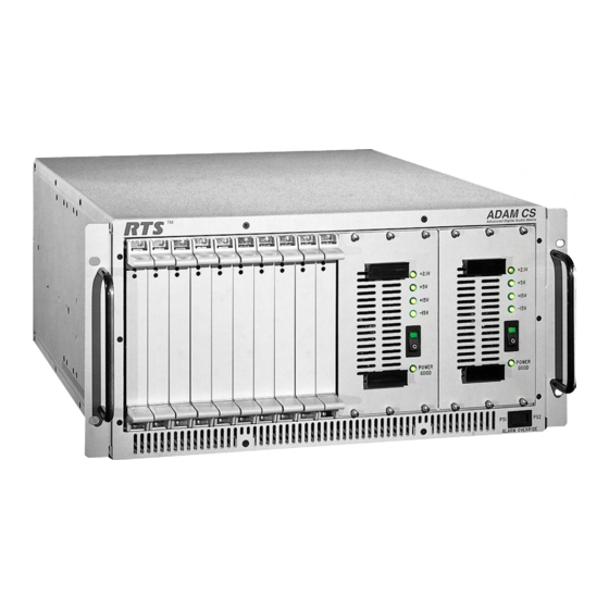
Page 18: Figure 1. Adam Cs Front View
Card Reset Switch Card Fail Indicator Figure 1. ADAM CS Front View J900 J901 J902 J900: RS232 TO CONFIGURATION PC J901: RS422/232 TO TRUNK MASTER J902: RS422/232 TO ACCESSORIES (PAP,UIO-256) J903: GENERAL PURPOSE INPUT/OUTPUT Figure 2. ADAM CS Back View (Shown with RJ-11 Connector Panel) 18 ADAM CS Installation Manual ™... -
Page 19: Figure 3. Adam Cs J900 To Computer Interconnect Cables (Adam Cs With Male J900 Connector)
TO INTERCOM SYSTEM RX 2 TX 3 GND 5 9-PIN FEMALE CONNECTOR (DE-9S) TO INTERCOM SYSTEM RX 2 TX 3 GND 5 9-PIN FEMALE CONNECTOR (DE-9S) Figure 3. ADAM CS J900 to Computer Interconnect Cables (ADAM CS with male J900 Connector) TO INTERCOM SYSTEM RX 4... -
Page 20: Figure 6. Rj-11 Intercom Cable
BELDEN 8777 IMPORTANT! When connecting to an ADAM CS back panel, use only low-profile cable connectors such as AMP Part No. 747516-3 (Telex Part No. 59926-678) Figure 7. 9-Pin Intercom Cable 20 ADAM CS Installation Manual TO INTERCOM MATRIX CONTACTS... -
Page 21: Figure 10. Typical Connections Of Ekp's And Lcp's To A
KP-12 Figure 10. Typical connections of EKP's and LCP's to a KP-12 DE-9S (Female) TO ADAM CS, J902 Figure 11. Program Assign Panel Data Cable for PAP-940, -951, and -952 (Female) TO ADAM CS Figure 12. Program Assign Panel Data Cable for PAP-950-50 ALL INTERCONNECTIONS BETWEEN PANELS USE SUPPLIED RJ-45 CABLES TO: PAP-940, PAP-951,... -
Page 22: Figure 13. Single-Pair Data Cable
DE-9S (Female) Figure 13. Single-Pair Data Cable DE-9S (Female) TO ADAM CS, J902 Figure 14. Cable for Parallel Connection of a UIO-256 and a Program Assign Panel 22 ADAM CS Installation Manual DA-15P DE-9P (Male) (Male) Figure 15. 15-Pin Data Cable GPI OUT + DE-9P (Male) -
Page 23: Figure 18. Trunking Audio Interconnect Cable With Rj-11 Connectors
DE-9S (Female) TO ADAM CS, J902 Figure 22. UIO-256 to ADAM CS Interconnect Cable RJ 11 MOD PLUG Figure 18. Trunking Audio Interconnect Cable with RJ-11 Connectors DE-9S (FEMALE) Figure 19. Trunking Audio Interconnect Cable with 9-Pin Connectors DE-9P (Male) RJ 11 TO UIO-256, J2 MOD PLUG... -
Page 24: Figure 23. Cdp-950 Cable Wiring Diagrams
DE-9S (FEMALE) TO AN INTERCOM PORT SINGLE PAIR DATA CABLE FOR CONNECTION OF CDP-950 ONLY DE-9S (FEMALE) DATA TO AN INTERCOM AUDIO TO MATRIX PORT AUDIO FROM MATRIX "Y" CABLE FOR CONNECTION OF CDP-950 AND AN INTERCOM STATION CABLES FOR CONNECTION TO AN INTERCOM SYSTEM THAT HAS DE-9P INTERCOM PORT CONNECTORS Figure 23. -
Page 25: Figure 24. 50-Pin Telco Cable Wiring Diagram
Figure 24. 50-Pin Telco Cable Wiring Diagram ADAM CS Installation Manual 25... -
Page 26: Figure 25. Trunking System Connections For Up To Eight Intercom Systems, Without Backup Controller
SHORTING PLUG NOTE 2 INTERCOM SYSTEMS (NOTE 4) Figure 25. Trunking System Connections for up to Eight Intercom Systems, without Backup Controller Notes: 1. 50-pin telco cable. See Figure 24. 2. Single pair data cable. See Figure 13. 3. Computer cable. See Figure 4. 4. -
Page 27: Figure 26. Trunking System Connections For Up To Eight Intercom Systems, With Backup Controller
To AC1 FR9589 MASTER CONTROLLER A (MAIN) SHORTING PLUG (MAIN ONLY) DE9P ICP-97-TMX #1 NOTE 2 INTERCOM SYSTEMS (NOTE 4) ICP-97-TMX #2 Figure 26. Trunking System Connections for up to Eight Intercom Systems, with Backup Controller Notes: 1. 50-pin telco cable. See Figure 24. 2. -
Page 28: Figure 27. Trunking System Connections For Up To Twelve Intercom Systems, Without Backup Controller
To AC1 FR9589 MASTER CONTROLLER A (MAIN) SHORTING PLUG DE9P ICP-97-TMX #1 NOTE 2 TO INTERCOM SYSTEMS (NOTE 4) Figure 27. Trunking System Connections for up to Twelve Intercom Systems, without Backup Controller Notes: 1. 50-pin telco cable. See Figure 24. 2. -
Page 29: Figure 28. Trunking System Connections For Up To Twelve Intercom Systems, With Backup Controller
To AC1 FR9589 MASTER CONTROLLER A (MAIN) SHORTING PLUG (MAIN ONLY) DE9P ICP-97-TMX #1 NOTE 2 TO INTERCOM SYSTEMS (NOTE 4) ICP-97-TMX #3 Figure 28. Trunking System Connections for up to Twelve Intercom Systems, with Backup Controller Notes: 1. 50-pin telco cable. See Figure 24. 2. -
Page 30: Table 1. Adam Cs Master Controller Card Dip Switch Settings (S1)
Table 1. ADAM CS Master Controller Card DIP Switch Settings (S1) Switch CSedit / ADAMedit baud rate select Off: 9600 baud On: 38.4 Kbaud Keypanel Incoming message option Off: Normal operation On: All callers display in Incoming Messages window Keypanel "in-use" and "busy" flash Off: Enable On: Disable Trunk master baud rate select. -
Page 31: Table 2. Relationship Between Audio Input/Output Cards, Intercom Ports, And Logical Keypanel Numbers
Table 2. Relationship between Audio Input/Output Cards, Intercom Ports, and Logical Keypanel Numbers ADAM CS Intercom Port Numbers (Grouped by Audio Input/Output Card Number) Table 3. Address DIP Switch Settings for KP-95/96/97/98 Keypanels and the TIF-951 Telephone Interface Logical Keypanel Number Address DIP Switch Settings SW 4... -
Page 32: Table 4. Cdp-950 Intercom Range Selection
Table 4. CDP-950 intercom Range Selection DIP Switch Number Ports Controlled #1 only Open Closed Closed #1 & #2 Closed Open Closed #1 - #3 Open Open Closed #1 - #4 Closed Closed Open #1 - #5 Open Closed Open #1- #6 Closed Open... -
Page 33: Table 8. Uio-256 Dip Switch Sw1 Settings For Input/Output Range
Table 8. UIO-256 DIP Switch SW1 Settings for Input/Output Range UIO-256 Input/Output Frame Range 1-16 Open 17-32 Open 33-48 Open 49-64 Open Table 9. UIO-256 GPI Outputs Connector (J5) Relay Output Numbers* UIO-256 #1 UIO-256 #2 Dependent on UIO-256 DIP Switch SW1 Settings for Input/Output Range as summarized in Table 8. The relay contacts are rated for 0.5A at 120 VAC;... -
Page 34: Table 10. Uio-256 Gpi Inputs Connector (J7)
Table 10. UIO-256 GPI Inputs Connector (J7) GPI Input Numbers* UIO-256 UIO-256 Frame #1 Frame #2 Dependent on UIO-256 DIP Switch SW1 Settings for Input/Output Range as summarized in Table 8. Inputs will sink 100 mA max at a maximum input voltage of +18 VDC. For operation from an external DC voltage source, connect the external control voltage to the "plus"... -
Page 35: Table 11. Planning Worksheet For Adam Cs With Rj-11 Or De9 Back Panel, Sheet 1 Of 3
Table 11. Planning Worksheet for ADAM CS with RJ-11 or DE9 Back Panel, Sheet 1 of 3 ADAM CS ADAM CS Logical Connector Audio I/O Keypanel Card No. Number* J100 J101 J102 J103 J104 J105 J106 J107 J200 J201 J202 J203 J204 J205... -
Page 36: Planning Worksheet For Adam Cs With Rj-11 Or De9 Back Panel, Sheet 2 Of 3
Planning Worksheet for ADAM CS with RJ-11 or DE9 Back Panel, Sheet 2 of 3 ADAM CS ADAM CS Logical Connector Audio I/O Keypanel Card No. Number* J306 J307 J400 J401 J402 J403 J404 J405 J406 J407 J500 J501 J502 J503 J504 J505... -
Page 37: Planning Worksheet For Adam Cs With Rj-11 Or De9 Back Panel, Sheet 3 Of 3
Planning Worksheet for ADAM CS with RJ-11 or DE9 Back Panel, Sheet 3 of 3 ADAM CS ADAM CS Logical Connector Audio I/O Keypanel Card No. Number* J604 J605 J606 J607 J700 J701 J702 J703 J704 J705 J706 J707 J800 J801 J802 J803... -
Page 38: Table 12. Planning Worksheet For Adam Cs With 50-Pin Telco Back Panel, Sheet 1 Of 3
Table 12. Planning Worksheet for ADAM CS with 50-Pin Telco Back Panel, Sheet 1 of 3 ADAM CS Audio Audio Audio Data Input Output Input/Output Connector Connector Connector Card No. * The Logical Keypanel Number is used to set the address DIP switches when connecting a KP-9X Series Keypanel or TIF-951. See Table 3, page 31, for address DIP switch settings. -
Page 39: Planning Worksheet For Adam Cs With 50-Pin Telco Back Panel, Sheet 2 Of 3
Planning Worksheet for ADAM CS with 50-Pin Telco Back Panel, Sheet 2 of 3 ADAM CS Audio Audio Audio Data Input Output Input/Output Connector Connector Connector Card No. * The Logical Keypanel Number is used to set the address DIP switches when connecting a KP-9X Series Keypanel or TIF-951. See Table 3, page 31, for address DIP switch settings. -
Page 40: Planning Worksheet For Adam Cs With 50-Pin Telco Back Panel, Sheet 3 Of 3
Planning Worksheet for ADAM CS with 50-Pin Telco Back Panel, Sheet 3 of 3 ADAM CS Audio Audio Audio Data Input Output Input/Output Connector Connector Connector Card No. * The Logical Keypanel Number is used to set the address DIP switches when connecting a KP-9X Series Keypanel or TIF-951. See Table 3, page 31, for address DIP switch settings. -
Page 41: Index
INDEX Audio I/O Card Card Slot Numbers Front panel view System clock signals Back Panel Back View Description CDP-950 Cable Wiring Diagrams Installation Notes Range select DIP switch settings Circuit Card Card blank for unused slots Card slot numbers Removal and Installation Reset Switch and Fail Indicator Computer Connection... - Page 42 Description DIP switch settings for IFB range DIP switch settings for panel number selection Setup and Connections Planning Worksheets ADAM CS with 50-pin telco back panel ADAM CS with RJ-11 or DE9 back panel Power Supply Alarm operation Installation and removal Supply loading Rack Mounting Return Authorization...
Need help?
Do you have a question about the MC-ADAM-CS and is the answer not in the manual?
Questions and answers