
Related Manuals for Elektro-Automatik EL 9000 HP


Summary of Contents for Elektro-Automatik EL 9000 HP
- Page 1 操作说明书 Operating Guide EL 9000 HP Electronic DC Load 直流电子负载 4800W EL 9080-400 HP: 33 200 241 EL 9160-200 HP: 33 200 243 Doc ID: EL9H4CN EL 9400-100 HP: 33 200 245 Revision: 06 EL 9750-50 HP: 33 200 250...
- Page 3 概述 © Elektro-Automatik 安全须知 严禁再版、复印或部分错误地使用本说明书,否则将承 担本行为导致的法律后果。 请仅在铭板标示电压下操作本仪器。 • 请勿将任何机械零件,特别是金属件,插入仪器内,否 • 则将有触电危险或损坏仪器。 请避免在仪器周围使用任何液体物质,因有可能进入仪 • 器内部并损坏它。 请勿将高于负载额定电压的电压源连接到负载上。比如 • 80V型号的负载,不能连接高于100V的电压源,160V 型号不能连接高于180V的电压源,400V的产品不能连 接460V电压源。 从后板插槽上安装接口卡时,请遵循一般防静电规则。 • 接口卡只能在仪器完全关闭(电源开关关闭)后插入和 • 取出。 当连接其它电压源或电池,或者使用模拟接口时,总是 • 先查看应用设备的各项限定值和标称值。 DC输入端无保险丝熔断保护! • • 内置模拟接口的AGND与DGND引脚从内部与DC输入 负极(DC-)连在一起。因此不可将这些引脚接地,因 为它会同时将DC+输入端也接地! EL 9000 HP 系列 日期:02-17-2014 产品说明书...
-
Page 4: Table Of Contents
6.11.3 横向调整 (两象限操作) ..............15 6.11.4 远程感测 (Remote sense) ..............15 6.11.5 System Bus-终端系统总线各引脚分布说明 ............15 7. 产品配置 ..................16 7.1 设置菜单 ..................16 8. 模拟接口 ..................17 8.1 重要提示 ..................17 8.2 配置举例 ..................17 8.3 应用举例 ..................18 8.4 模拟接口各引脚分布说明 ..............19 9. 接口卡 ..................20 10. 附件 ...................20 10.1 其它附件和选项功能 ................20 EL 9000 HP 系列 日期:02-17-2014 产品说明书... -
Page 5: 技术规格
可 拔 插 式 接 口 卡 ( C A N , U S B , R S 2 3 2 , I E E E / • 0.00Ω…99.99Ω 格式: GPIB,Ethernet/LAN) 0.0Ω...999.9Ω 外控用模拟接口 • 带可调脉宽和可调升/降时间的两组设定值间的脉动 • 时间显示 操作 累计时间(仅在电池测试模式下)以小时:分钟:秒钟格 在50µs...100s时间范围内的可调占空比(随时间),在 • 式(HH:MM:SS)显示。 30µs...200ms时间范围内可调上升时间。 分辨率: 与CAN系统兼容的Vector软件 • 1s...99h:59m:59s (99:59:59) 范围: 通过任意一款插拔式接口卡可读出时间标记,以及动态 Level A/B操作模式下的脉宽和上升时间。这些动态值也 可远程设置。为达此目的,需扩展时间格式使之能显示 1µs到几年的时间。 相关详细信息请参考接口卡用户操作说明。 EL 9000 HP 系列 日期:02-17-2014 产品说明书... -
Page 6: 各产品型号详细规格
19" x 6U x 460mm 重量 35kg 支持的接口卡 CAN, USB, RS232, GPIB, Ethernet 产品编号 33 200 241 33 200 243 33 200 245 33 200 250 * 关于技术规格请参考章节“模拟接口” ** 精确度是在不考虑温差或元件老化条件下由实际值(比如:输出电压)和调整后设定值之间的差异而定义的。 *** 上升和下降时间定义在标称 值的10%...90%和 90%...10% 之间。 所有指定误差的单体数值都为典型值。 EL 9000 HP 系列 日期:02-17-2014 产品说明书... -
Page 7: 前视图
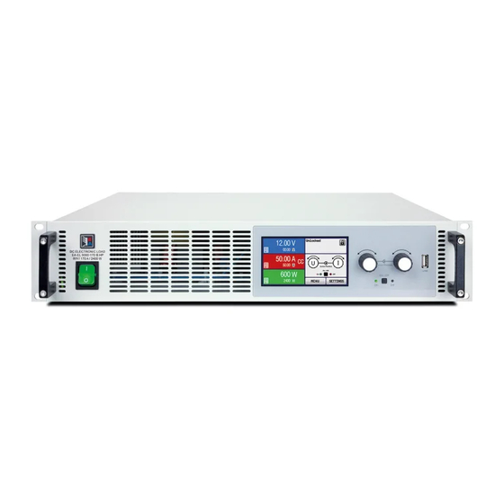
关于产品 3. 外观 3.1 前视图 图 1 3.2 后视图 图 2 EL 9000 HP 系列 日期:02-17-2014 产品说明书... -
Page 8: 供应清单
或修理。 4.5 温控关断/通风 4.8 输入电压和输入电流间的关系 本产品装有长期运转的温控风扇。遇高温时,RPM增加, 当应用设备只有低压供给负载时,必须知道负载吸取全输 并产生一定噪音。 入电流所需的最低输入电压。 如遇过热,产品自动关闭(待机)。待冷却至允许温度范 最低电压不为零,根据内部三极管的数量,不同型号的 围产品又自动打开。 电压不同。 下面以EL 9080-400的曲线为例: 4.6 动态特性和稳定准则 本电子负载特征在于电流升降时间非常短,这是由其内部 EL9080-400 调整线路的高带宽完成的。 zu U to U 如果负载连上带有自身调整线路的测试源,如电源,可 能出现调整不稳定现象。这个不稳定性是整个系统(馈源 和电子负载)在特定频率下的相位和增益余量太少而形成 的。180°相位位移在>0dB的放大条件下,会导致振荡或 不稳定。如果连接线是高导电性的或电感-电容性的, 无调整线路的使用源(如:电池)也可能出现相同情况。 此不稳定性不是负载的误操作造成,而是整个系统的动 作。改善后的相位和增益余量可解决此问题。实际应用 中,可在负载直流输入端直接装个电容。建议用1µF, 功率较低的产品100µF电容可能已足够。 EL 9000 HP 系列 日期:02-17-2014 产品说明书... -
Page 9: 与市电的连接
注意!将其中一输入极接地时,请随时检查馈源(如电 源)输出端的其中一极是否也已接地。否则将引起短路! 连接„System Bus“端子 5.5 System Bus (产品后面)端子为另一个具有重要特点的接 口。其引脚说明和详细描述请见章节„6.11 System Bus端 子的功能“。 此端子上的任何连接都必须在产品关闭后方可执行! 5.6 远程感测的使用和连接 远程感测线连到System Bus端子上,更多信息请见章 节6.11。 为补偿馈源和负载器间负载线(每根线最大1.1V)的压降, 负载器可测量System Bus远程感测端馈源的电压,然后 进行相应调整。按正确极性连接到产品后面的System Bus端子的引脚1(+感测端)和引脚4(–感测端)。建议使用 – 2,5mm 直径为0,2mm ,带线端护套的弹性线。 (+) 感测端只能与馈源(+)输出端相连,(–)感测端与输 出(–)端相连,否则可能会损坏本产品。 5.7 接口卡插槽 本产品可配接口卡。接口卡插槽位于产品后面。关于接口 卡更多信息见章节9。 EL 9000 HP 系列 日期:02-17-2014 产品说明书... - Page 10 显示屏右半边的这部分内容指示不同的操作模式和错误 图 7 种类: 被激活的报警信息总是优先于消失的报警信息。如果两 个报警都出现,那么过压要优先于断电而出现在显示屏 上。 图 5 只有出现“(gone)”状态的报警才能确认。可使用“nput on/off”按钮或经数字接口卡读取内部缓冲区的报警信息 当负载器通过可选接口卡设置在远程控制模式下(Remote 来确认。若当前不再有激活的报警信息,则读取后就会 mode)时出现这部分内容。在模式则可能为Level A, B 清空缓冲区。 和 A/B。 在模拟远程控制模式,必须将REM-SB引脚拉至low,即 关闭输入,方能确认报警信息。若报警出现时输入已关 闭,则会自动确认并变为“(gone)”状态。 图 6 提示:插上GPIB或Ethernet接口卡后,他们会不断地读 mode表示负载的控制已经转到模拟接口。 文本External 取内部报警缓冲区内的信息,并自动确认消失的错误, 在此模式下不可在本机对设定值进行调节。详情请见章节 而不再显示于显示屏上。通过SCPI指令进行的操作,不 会返回处于“(gone)”状态的错误,而仅仅是激活状态 „8. 模拟接口“。 的错误。 EL 9000 HP 系列 日期:02-17-2014 产品说明书...
-
Page 11: 操作按钮
,设定值会重设为默认值。用Level Control (3)选择器可 本负载由主电源开关打开。负载打开后产品型号和固件 关闭负载输入,除非是从A->B或者从B->A,因为这两个 版本显示于屏幕上。 等级只能手动转换。 内部系统被启动并执行一些测试,如:设置默认设定值或 恢复最后的设定值,这取决于Keep set values 当负载被关闭或者主电源欠压(断电)时,最近的设定值 的设置。 被存储。负载重新打开后,且Keep set values = yes被 负载的直流输入在第一次启动后始终是关闭的。 选,则会恢复最近存储的设定值。 选择器各位置说明: 转至Level A的设定值,相关数值即刻生效, 并能被更改。 转至Level B的设定值,相关数值即刻生效, 并能被更改。 关闭负载,激活脉冲模式(频率受控,自动在 Level A和B间转换)。 Battery 关闭负载,激活电池测试模式。 Setup 关闭负载,激活设置菜单。在此处设置产品和 接口卡(如果装有的话)。 EL 9000 HP 系列 日期:02-17-2014 产品说明书... -
Page 12: 打开Input On/Off开关
值必须始终大于或等于Level B的!Level B只可向上调 也不能达到调整后的阻值。 节到Level A的数值,而Level A可向下调节到Level B 如果Keep set values参数被设为no,转至CR模式可将电 的数值。 阻抗、电流和功率设定值恢复至标称值。如果是yes,保留 调整最小的设定值。详情见„7.1 设置菜单“。 6.6 预选调整模式 选择器Mode (2)预选内部调整特性的调整模式。有4种模 式可选: CC, CV, CP 和 CR。设定值将决定产品后续的 真实操作行为。 指恒流。此时可调节电流和功率设定值。在此模式 下输入电流被调整并限定为调节值(限流),只要馈源能 输出电流。功率设定值另外限定消耗功率,影响最大电 流。功率限制优先于电流限制。 如果Keep set values参数被设为no,转至CC调整模式 可将功率设定值重设为标称值,电流设定值为0。如果是 yes,保留调整最小的设定值。详情见„7.1 设置菜单“。 EL 9000 HP 系列 日期:02-17-2014 产品说明书... -
Page 13: Level A和Level B的使用
Level B模式下负载可通过接口转换至电脑遥控,以便像 手动操作一样控制和监视。 转换至遥控模式后,当前选择的Level Control设置被替 代,用指令可进行更改,除GPIB接口卡IF-G1外。 6.7.3 Level A/B (脉动操作) 这个模式将A和B的两组设定值组合在一起,而且A和B各 自的可调脉宽都不同。电子负载通过这些数值自动生成A 和B间的设定值阶跃,且其上升/下降时间可调。脉动操 作只适合应用属于被选模式的设定值。意思是,在CV模 式下,只有电压会受影响,而其它设定值保持不变。详 情请参考图11和12。 图 12 A的脉宽对应A的设定值。脉宽总和形成一个时间段t,它 代表一定的频率f=1/t。脉宽在50µs...100s间可调,从而形 图12显示了设定值((U, I, P or R) 和可调脉宽和可变振幅 成100µs...200s的时间段,对应10kHz...0.005Hz频率段。 的变化图。升/降时间也可调,但A和B值相等。 注意:像OVP或PF(缺电)(见章节6.1的“报警管理器”) 如果升/降时间设至最小,脉动操作的信号接近理想方波 一样可关闭输出的报警也终止脉动操作。而且只要报警 形状。图12只是一个阐述图。举一个实际变化的例子: 被确认并清除方可恢复。 由1KHZ频率脉动形成的输入电流会多少有些不同。这 取决于很多条件,比如馈电源的调整时间,负载的调整 时间,连接线的阻抗等。 EL 9000 HP 系列 日期:02-17-2014 产品说明书... -
Page 14: 升/降时间
对电池定义性地放电。测量平均电流,计算累计时间, (遥控)。为防止用户一次性从两个区域访问负载器而设 然后将消耗容量以AH显示出来。电压监控和可调欠压一 置了优先顺序。适用如下: 起关闭Ulow极限,防止电池过放。这个极限需调整至少 模拟接口具有最高优先权,数字接口第二,手动控制最 一次。如果测试过程中超过极限,负载输入自动关闭, 低。意思是如果产品被设为遥控,则不可用开关和旋钮 计时器终止。电池不再输出电流。如果极限大于电池电 设置模式和设定值。如果在遥控运行同时转换到外控,遥 压,测试则不能开始。 控状态将被重设,负载只能通过模拟输入控制。为了将此 选择调整模式 报告给电脑上运行的软件,尝试访问和控制负载器,控制 可在任何时候更改调整模式,即使正在运行测试也可以。 区域内部设为“local”。在“local”状态下负载器能通过 该操作可重设整个测试,包括计时器和Ah值。 电脑读取(即:监控)。 使用 6.10 串联和并联连接 测试之前和测试过程中都可进行调整模式设定值的调节, 多台负载可以并联,但也不是完全支持。意思是,并联时 欠压会关闭Ulow极限。用Selection(5)选定设定值。用 电流不会自动分配。故用户需注意正确控制产品。 Setting(6)调节。显示器以小时:分:秒(HH:MM:SS)的 并联操作时,通过控制板或接口卡(数字或模拟)对并 格式显示累计时间,以Ah为单位显示消耗容量。 联中所有产品的U,I,P和R调节成相同数值,从而达到平 计算Ah值 均分配的效果。 安培小时值(吸取的电荷)是最后两次测得的输入电流的平 均值乘以所用时间而计算出来的。 注意!本系列产品不可串联!否则产品会受损。 EL 9000 HP 系列 日期:02-17-2014 产品说明书... -
Page 15: System Bus端子的功能
Pin 6 = AGnd 共享总线操作过程中,电子负载当引导设备,电源当依 托设备。 Pin 7 = FastReg 两象限操作的典型应用: 能进行自动充放电循环的电池测试 • 带模拟三极管的汽车电子测试,如在引擎发动时的电 • 压中断 电容周期性充放电 • 6.11.2 选择调整速度 负载的调整速度(或时间)事先故意设为慢速,典型值为 50ms (只针对CV和CP模式)。通过此设置可稳定地载荷 像具未知调整特性的电源一样的关键馈源,并在无隔离 条件下运行。在给出最小调整时间内进入动态。见„2.2 各产品型号详细规格“章节“动态值”。 如需要更好的调整动态,可将负载转至快速调整。这需在 终端System Bus-系统总线的第7引脚(FastReg)和第6引 脚(AGnd)上完成。如果这些引脚被短路,快速调整启动。 默认状态时为慢速调整。 只有在负载完全与主电源断开后 才可改变此设置! 图 13. 电流控制模式下的电池测试操作 EL 9000 HP 系列 日期:02-17-2014 产品说明书... -
Page 16: 产品配置
(自5.01固件版本才有) 保本设置设为no。 可选设置:normal, Vector RS232 Baud rate 默认设置:normal 19200 38400 57600 Bd 可选设置:9600 属于:CAN接口卡IF-C1 默认设置:57600 Bd 解释:本设置可让用户选择每台机需用2个ID的normal 属于:RS232接口卡IF-R1 CAN ID系统,还是与CAN ID系统兼容,每台机需用3个 解释:使用串行RS232接口卡IF-R1时,决定串行数据 ID的Vector系统。选择normal系统, 由Devicel, node和 传输的波特率(传输速度)。确保串联的另外一端以相同 Relocatable ID(见接口卡说明书上的计算公式)给每台 波特率操作。 机创建2个ID。选择Vector系统, 产品会分配3个CAN ID, 从基本ID(如下)开始,在整个ID范围(11位元, 0...2047) EL 9000 HP 系列 日期:02-17-2014 产品说明书... -
Page 17: 模拟接口
Pin 12 = Low = 激活阻抗调整 Pin 12 = High = 停用阻抗调整 如果使用阻抗调整,在使用模拟接口前或期间选择阻 • 值范围。13引脚(R-Range)用于在两组范围间转换: Pin 13 = Low = 使用阻值范围2 Pin 13 = High = 使用阻值范围1(默认) Rem-SB输入端(远程待机,引脚8)优先于Input on/ • off(4)按钮。意思是:您可使用本引脚在任何时间关闭 负载器(即使没有通过模拟接口将负载器设置为外部控 制),只要本引脚固定于0V,负载器输入永久为关闭状 态,也无法用Input on/off(4)按钮或接口卡的远程控 制打开。 EL 9000 HP 系列 日期:02-17-2014 产品说明书... -
Page 18: 应用举例
至VMON都可用来控制一台或多台辅助负载器的四组设定 控模式即可。转换通过极端器或开关来实现。 值输入中的一组。 注意!需先给出所有设定值,内阻设定值除外,如果内阻 控制激活的话。设定值也可100%地连到引脚。 Master CMON AGnd REMOTE DGND REM-SB DGND Slave 图 19 DGnd PSEL 外控电流和功率 图 17 图20的例子显示对应VREF(10V)和AGND的功率和电流 因为无功率监控输出,PSEL输入不能由主负载器来控 设定值的可调电位器。通过这些电位器您可在0%至100% 制。但可将它直接固定于VREF输出或通过可调电位器固 之间任意调节。 定,从而在0%至100%之间调节。Remote和R-active输 DGND 入脚必须固定在辅机的GND脚上,从而启动外控模式。 VREF CSEL AGND PSEL 图 20 EL 9000 HP 系列 日期:02-17-2014 产品说明书... -
Page 19: 模拟接口各引脚分布说明
无 OT 或 OVP = LOW (U < 1V) 输出端为15V时将有最大+1,5mA电流 对DGND断路时有保护功能 接收器:U <1V, U > 4V High 备注:从模拟接口输出正向电流,输入负电流。 AI = 模拟输入 RSEL引脚需要设定一阻抗设定值 DI = 数字输入 只针对Level A/B 操作模式,要求在设置菜单内启用 DO = 数字输出 见技术规格 AO = 模拟输出 EL 9000 HP 系列 日期:02-17-2014 产品说明书... -
Page 20: 接口卡
水冷式结构 关于接口卡的更多信息和技术规格可参考其用户指导说 可内置水冷设备。不再需要额外的风扇,但在过温时关 明。 断功率阶段的输出。水冷式结构旨在获取更高连续输入 功率的同时,减少负载的随温功率降额,亦或避免随温 降额的出现。 特点 通过其中一接口卡和所供LabView VIs软件控制电子负载 器要遵循产品操作条件和各标称值。应检查设定值的合理 性,如有必要应更正或者强行改为标称值。 LabView 我们提供现成的LabView VIs接口卡软件。它不支持电子 负载的所有功能,但在不断开发和增强其功能。 在其它环境下的编程 数字通讯接口在除LabView外的其它IDEs也能普遍应用。 这个通讯协议不遵从任何标准,只代表通讯的最低级别。 在此等别下错误设置和错误设定值的安全级别较低,有可 能导致产品的误动作。请严格按照准则强制性地执行。 关于通讯协议的详细信息可参考接口卡用户指导说明。 应用举例 右边这些图片显示通过电脑控制一台或多台负载器的多种 应用的几种。这同样应用于与电源混合配置。 图 22 图23的设置也可限制性地应用于RS232和IF-R1接口 卡。LabView VIs 软件通过RS232目前只支持一台负载。 图 23 EL 9000 HP 系列 日期:02-17-2014 产品说明书... - Page 23 Pins AGND and DGND of the built-in analog inter- • face connector are internally wired to the negative DC input (DC-). Thus it is not possible to ground the- se pins the same time DC+ input is also grounded! Instruction Manual Date: 02-17-2014 EL 9000 HP Series...
- Page 24 Important notes ............................39 8.2 Example configurations ..........................39 Example applications ........................... 40 Pin assignment of the analogue interface ....................41 Interface cards..............................42 10. Miscellaneous..............................43 10.1 Accessories and options ..........................43 Instruction Manual Date: 02-17-2014 EL 9000 HP Series...
- Page 25 Adjustable duty cycle (as time) of 50µs...100s and • Detailed information about this can be found in the ope- adjustable rise time of 30µs...200ms rating guide of the interface cards. Vector software compatible CAN system • Instruction Manual Date: 02-17-2014 EL 9000 HP Series...
- Page 26 Example: nom. value is 400A and accuracy is given with 0.2%. A set value of 20A may thus result in an actual value of 19.2A...20.8A. *** Rise and fall time are defined at 10%...90% and 90%...10% of the nominal value All single values, which specify a tolerance are typical values Instruction Manual Date: 02-17-2014 EL 9000 HP Series...
- Page 27 About the device Design Front view Figure 1 Rear view Figure 2 Instruction Manual Date: 02-17-2014 EL 9000 HP Series...
- Page 28 At higher temperatures, the RPM will increase and result in a certain noise de- velopment. In case of overheating the device is automatically swit- ched offline (standby). After cooling down to the allowed temperature range it is automatically switching online again. Instruction Manual Date: 02-17-2014 EL 9000 HP Series...
- Page 29 The unit can be equipped with an optional interface card. The slot to insert the card is located at the rear side. Further information about the interface cards can be found in section 9. Instruction Manual Date: 02-17-2014 EL 9000 HP Series...
- Page 30 Via SCPI command, er- rors with status „(gone)“ are not returned, only active errors. Instruction Manual Date: 02-17-2014 EL 9000 HP Series...
- Page 31 The most recent set values are stored inside the unit when the unit is switched off or at mains undervoltage (power fail), and are restored after switching it on again, if the setting Keep set values = yes has been chosen. Instruction Manual Date: 02-17-2014 EL 9000 HP Series...
- Page 32 If the feeding source is able to deliver more current than the device is able to withdraw, then the voltage limit can not be achieved. Instruction Manual Date: 02-17-2014 EL 9000 HP Series...
- Page 33 When changing to remote control the currently selected Level Control setting is taken over and can then be changed by a command, except with GPIB interface IF-G1. Instruction Manual Date: 02-17-2014 EL 9000 HP Series...
- Page 34 A and B can only be done via the trigger input. Figure 11 Figure 9. Normal load operation in CP regulation mode Figure 10. Level A/B operation with pulse width adjustment Instruction Manual Date: 02-17-2014 EL 9000 HP Series...
- Page 35 Note:The time display is not 100% exact. The deviation by the device. of the displayed time to the actually elapsed time can be 1-2 seconds per hour. Instruction Manual Date: 02-17-2014 EL 9000 HP Series...
- Page 36 Automotive electronic tests with simulation of transients • like for example voltage break-ins during engine starts Cyclic charging and discharging of capacitors • Figure 13. Battery test operation in current control (CC) mode Instruction Manual Date: 02-17-2014 EL 9000 HP Series...
- Page 37 Up to 30 devices can be controlled from one PC. Within a bus system like CAN or GPIB, every address must only be given once. Instruction Manual Date: 02-17-2014 EL 9000 HP Series...
- Page 38 The base ID is adjustable in steps of four. Also see the further documentation for the Vector system, which is included with the databases. Note: this setting is only availabe, if CAN ID System: Vector has been selected (see above). Instruction Manual Date: 02-17-2014 EL 9000 HP Series...
- Page 39 Pin 13 (R-Range) is used to switch between the two ranges: Pin 13 = Low =Resistance range 2 is used Pin 13 = High = Resistance range 1 is used (default) Instruction Manual Date: 02-17-2014 EL 9000 HP Series...
- Page 40 Opening the contact again will either switch the output on if it was on before switching off (remote control) or enable switching it on again manually on the front panel. Figure 20 Instruction Manual Date: 02-17-2014 EL 9000 HP Series...
- Page 41 RSEL DO = Digital output ³ only for Level A/B operation, requires to be enabled in the setup menu see technical specs AO = Analogue output Instruction Manual Date: 02-17-2014 EL 9000 HP Series...
- Page 42 A strict adherence of the guidelines is mandatory. Details about the communication protocol can be found in the operating guide of the interface cards. Instruction Manual Date: 02-17-2014 EL 9000 HP Series...
- Page 43 The watercooling is used to gain a higher continuous input power and can decrease the temperature-depending power derating of the load, or even avoid it completely. Instruction Manual Date: 02-17-2014 EL 9000 HP Series...
Need help?
Do you have a question about the EL 9000 HP and is the answer not in the manual?
Questions and answers