Table of Contents
Advertisement
Available languages
Available languages
Quick Links
Distributed by:
dataTec ▪ Ferdinand-Lassalle-Str. 52 ▪ 72770 Reutlingen ▪ Tel. 07121 / 51 50 50 ▪ Fax 07121 / 51 50 10 ▪ info@datatec.de ▪ www.datatec.de
Betriebsanleitung
EL 9000 DT
Elektronische DC-Last
Achtung! Diese Anleitung gilt nur
für Geräte mit einer Firmware ab
„KE: 3.04" und „HMI: 2.10" und
„DR: 1.6.4". wecks Verfügbarkeit
von Updates bitte unsere Websei-
te aufsuchen oder anfragen.
Doc ID: EL9DDE
Revision: 03
Date: 09/2017
Advertisement
Chapters
Table of Contents

Subscribe to Our Youtube Channel
Related Manuals for Elektro-Automatik EL 9000 DT Series


Summary of Contents for Elektro-Automatik EL 9000 DT Series
- Page 1 Betriebsanleitung EL 9000 DT Elektronische DC-Last Achtung! Diese Anleitung gilt nur für Geräte mit einer Firmware ab „KE: 3.04“ und „HMI: 2.10“ und Doc ID: EL9DDE „DR: 1.6.4“. wecks Verfügbarkeit von Updates bitte unsere Websei- Revision: 03 te aufsuchen oder anfragen. Date: 09/2017 Distributed by: dataTec ▪...
-
Page 3: Table Of Contents
3.10.8 Trapez-Funktion ...........61 2.3.9 Erstinbetriebnahme ........29 3.10.9 DIN 40839-Funktion........61 2.3.10 Erneute Inbetriebnahme nach Firmwareup- 3.10.10 Arbiträr-Funktion ..........62 dates bzw. längerer Nichtbenutzung ...29 EA Elektro-Automatik GmbH Telefon: 02162 / 3785-0 www.elektroautomatik.de Seite 3 Helmholtzstr. 31-37 • 41747 Viersen Telefax: 02162 / 16230 ea1974@elektroautomatik.de... - Page 4 Firmware-Aktualisierungen ......73 Nachjustierung (Kalibrierung) ......74 4.3.1 Einleitung ............74 4.3.2 Vorbereitung ..........74 4.3.3 Abgleichvorgang ..........74 SERVICE & SUPPORT Reparaturen ..........76 Kontaktmöglichkeiten ........76 EA Elektro-Automatik GmbH Telefon: 02162 / 3785-0 www.elektroautomatik.de Seite 4 Helmholtzstr. 31-37 • 41747 Viersen Telefax: 02162 / 16230 ea1974@elektroautomatik.de...
-
Page 5: Allgemeines
Hinweissymbol für allgemeine Sicherheitshinweise (Gebote und Verbote zur Schadensverhütung) Allgemeiner Hinweis Gewährleistung und Garantie Elektro-Automatik garantiert die Funktionsfähigkeit der Geräte im Rahmen der ausgewiesenen Leistungsparameter. Die Gewährleistungsfrist beginnt mit der mängelfreien Übergabe. Die Garantiebestimmungen sind den allgemeinen Geschäftsbedingungen (AGB) der EA Elektro-Automatik GmbH entnehmen. -
Page 6: Entsorgung Des Gerätes
Ein Gerät, das zur Entsorgung vorgesehen ist, muß laut europaweit geltenden Gesetzen und Verordnungen (Elek- troG, WEEE) von Elektro-Automatik zurückgenommen und entsorgt werden, sofern der Betreiber des Gerätes oder ein von ihm Beauftragter das nicht selbst erledigt. Unsere Geräte unterliegen diesen Verordnungen und sind dementsprechend mit diesem Symbol gekennzeichnet: Produktschlüssel... -
Page 7: Sicherheit
Spannung erzeugen kann, die höher ist als 120% der Nenneingangs-Spannung der Last. Das Gerät ist gegen Überspannungen nicht geschützt, diese können das Gerät zerstören. • Konfigurieren Sie Schutzfunktionen gegen Überstrom usw., die das Gerät für die anzuschlie- ßende Quelle bietet, stets passend für die jeweilige Anwendung! EA Elektro-Automatik GmbH Telefon: 02162 / 3785-0 www.elektroautomatik.de Seite 7 Helmholtzstr. -
Page 8: Verantwortung Des Bedieners
Gefahren ausführlich und nachweislich unterrichtet wurden. Als Fachpersonal gilt, wer aufgrund seiner beruflichen Ausbildung, Kenntnisse und Erfahrungen sowie Kenntnis der einschlägigen Bestimmungen in der Lage ist, die übertragenen Arbeiten ordnungsgemäß auszuführen, mög- liche Gefahren selbständig zu erkennen und Personen- oder Sachschäden zu vermeiden. EA Elektro-Automatik GmbH Telefon: 02162 / 3785-0 www.elektroautomatik.de Seite 8 Helmholtzstr. -
Page 9: Alarmsignale
Farbiger TFT-Touchscreen mit Gorillaglas, 4.3“, 480 x 272 Punkte, kapazitiv Bedienelemente: 2 Drehknöpfe mit Tastfunktion, 1 Drucktaste Die Nennwerte des Gerätes bestimmen den maximal einstellbaren Bereich. EA Elektro-Automatik GmbH Telefon: 02162 / 3785-0 www.elektroautomatik.de Seite 9 Helmholtzstr. 31-37 • 41747 Viersen Telefax: 02162 / 16230 ea1974@elektroautomatik.de... -
Page 10: Spezifische Technische Daten
4,91 A...5,09 A betragen. (2 Bei 25°C Umgebungstemperatur (3 Die Genauigkeit der Anzeige addiert sich zur Genauigkeit der Istwerte am DC-Eingang (4 Inkludiert die Genauigkeit des angezeigten Istwertes EA Elektro-Automatik GmbH Telefon: 02162 / 3785-0 www.elektroautomatik.de Seite 10 Helmholtzstr. 31-37 • 41747 Viersen Telefax: 02162 / 16230 ea1974@elektroautomatik.de... - Page 11 ~ 6,5 kg Artikelnummer 33210501 33210502 33210503 33210503 33210504 (1 Technische Daten der Analogschnittstelle siehe „3.5.4.4 Spezifikation der Analogschnittstelle“ auf Seite 49 EA Elektro-Automatik GmbH Telefon: 02162 / 3785-0 www.elektroautomatik.de Seite 11 Helmholtzstr. 31-37 • 41747 Viersen Telefax: 02162 / 16230 ea1974@elektroautomatik.de...
- Page 12 4,91 A...5,09 A betragen. (2 Bei 25°C Umgebungstemperatur (3 Die Genauigkeit der Anzeige addiert sich zur Genauigkeit der Istwerte am DC-Eingang (4 Inkludiert die Genauigkeit des angezeigten Istwertes EA Elektro-Automatik GmbH Telefon: 02162 / 3785-0 www.elektroautomatik.de Seite 12 Helmholtzstr. 31-37 • 41747 Viersen Telefax: 02162 / 16230 ea1974@elektroautomatik.de...
- Page 13 ~ 7,5 kg Artikelnummer 33210506 33210507 33210508 33210509 33210510 (1 Technische Daten der Analogschnittstelle siehe „3.5.4.4 Spezifikation der Analogschnittstelle“ auf Seite 49 EA Elektro-Automatik GmbH Telefon: 02162 / 3785-0 www.elektroautomatik.de Seite 13 Helmholtzstr. 31-37 • 41747 Viersen Telefax: 02162 / 16230 ea1974@elektroautomatik.de...
-
Page 14: Ansichten
B - Bedienteil F - Fernsteuerungs-Schnittstellen (digital, analog) C - Front-USB-Port (Typ A) G - Lüfterausgang D - DC-Eingang H - Netzanschluß EA Elektro-Automatik GmbH Telefon: 02162 / 3785-0 www.elektroautomatik.de Seite 14 Helmholtzstr. 31-37 • 41747 Viersen Telefax: 02162 / 16230... - Page 15 EL 9000 DT Serie Bild 3 - Seitenansicht von links, liegend Bild 4 - Ansicht von oben EA Elektro-Automatik GmbH Telefon: 02162 / 3785-0 www.elektroautomatik.de Seite 15 Helmholtzstr. 31-37 • 41747 Viersen Telefax: 02162 / 16230 ea1974@elektroautomatik.de...
-
Page 16: Bedienelemente
Stoppen einer Funktion. Die beiden LEDs „On“ und „Off zeigen den Zustand des DC-Eingangs an, egal ob bei manueller Bedienung oder Fernsteuerung USB Host-Steckplatz Typ A Dient zur Aufnahme handelsüblicher USB-Sticks. Siehe Abschnitt „1.9.5.5. USB-Port (Vorderseite)“ für weitere Informationen. EA Elektro-Automatik GmbH Telefon: 02162 / 3785-0 www.elektroautomatik.de Seite 16 Helmholtzstr. 31-37 • 41747 Viersen Telefax: 02162 / 16230 ea1974@elektroautomatik.de... -
Page 17: Aufbau Und Funktion
Für diese Geräte gibt es folgendes Zubehör: 19" PSI/EL 9000 DT Metallrahmen-Kit zum Einbau eines PSI 9000 DT Gerätes in ein 19"-System (Schrank, Rack). Höhe: 2 HE. Bestell-Nr. 10 400 111 EA Elektro-Automatik GmbH Telefon: 02162 / 3785-0 www.elektroautomatik.de Seite 17 Helmholtzstr. 31-37 • 41747 Viersen Telefax: 02162 / 16230 ea1974@elektroautomatik.de... -
Page 18: Die Bedieneinheit (Hmi)
Gilt auch für weitere, auf diese phys. Größe bezogene Werte, wie z. B. OVD zur Spannung oder UCD zum Strom Der minimal einstellbare Widerstand variiert je nach Modell. Siehe technische Daten in 1.8.3 EA Elektro-Automatik GmbH Telefon: 02162 / 3785-0 www.elektroautomatik.de... - Page 19 1.9.5.3 Tastfunktion der Drehknöpfe Die Drehknöpfe haben eine Tastfunktion, die überall wo Werte gestellt werden können, zum Verschieben des Cursors von niederwertigen zu höherwertigen Dezimalpositionen (rotierend) des einzustellenden Wertes dienen: EA Elektro-Automatik GmbH Telefon: 02162 / 3785-0 www.elektroautomatik.de Seite 19 Helmholtzstr.
- Page 20 (1-10) und nicht verknüpft mit der Nummer eines Benutzerprofils im HMI. Beim Laden werden max. 10 Profile zur Auswahl angezeigt. mpp_result_<nr>.csv Ergebnisdaten des MPP-Tracking-Modus‘ 4 als Tabelle mit 100 Wertegruppen (Umpp, Impp, Pmpp) EA Elektro-Automatik GmbH Telefon: 02162 / 3785-0 www.elektroautomatik.de Seite 20 Helmholtzstr. 31-37 • 41747 Viersen Telefax: 02162 / 16230 ea1974@elektroautomatik.de...
-
Page 21: Usb-Port (Rückseite)
(Vorderseite, zwischen den DC-Klemmen) polrichtig mit der Quelle verbunden wer- den. Das Gerät erkennt automatisch, ob die Fernfühlung (Sense+) angeschlossen ist und regelt die Eingangsspannung entsprechend aus. Die max. Kompensation ist in den technischen Daten aufgeführt. EA Elektro-Automatik GmbH Telefon: 02162 / 3785-0 www.elektroautomatik.de Seite 21 Helmholtzstr. 31-37 • 41747 Viersen Telefax: 02162 / 16230 ea1974@elektroautomatik.de... -
Page 22: Installation & Inbetriebnahme
Es wird empfohlen, die komplette Transportverpackung (Lieferverpackung) für die Lebensdauer des Gerätes aufzubewahren, um sie für den späteren Transport des Gerätes an einen anderen Standort oder Einsendung des Gerätes an Elektro-Automatik zwecks Reparatur wiederverwenden zu können. Im anderen Fall ist die Verpackung umweltgerecht zu entsorgen. - Page 23 Dieses Gerät ist aufgrund seiner Konstruktion ein Tischgerät und sollte daher möglichst nur auf horizontalen Ober- flächen aufgestellt werden, deren Tragfähigkeit für das Gewicht des Gerätes ausreicht. Zulässige und unzulässige Aufstellpositionen: Aufstellfläche Aufstellfläche EA Elektro-Automatik GmbH Telefon: 02162 / 3785-0 www.elektroautomatik.de Seite 23 Helmholtzstr. 31-37 • 41747 Viersen Telefax: 02162 / 16230...
- Page 24 Anschlag in . 7. Rahmen komplett einschieben und fixieren (Befestigungsschrauben nicht im Lieferumfang enthalten). 8. Verbindung zur Quelle herstellen. Der DC-Eingang ist auf der Vorderseite des Gerätes. Bild 6 - Position (-90°) des Tragegriffs zwecks Demontage EA Elektro-Automatik GmbH Telefon: 02162 / 3785-0 www.elektroautomatik.de Seite 24 Helmholtzstr.
- Page 25 EL 9000 DT Serie Bild 7 - Abnehmen des Front- und Rückseitenrahmens Bild 8 - Montageschritte für den Einbaurahmen EA Elektro-Automatik GmbH Telefon: 02162 / 3785-0 www.elektroautomatik.de Seite 25 Helmholtzstr. 31-37 • 41747 Viersen Telefax: 02162 / 16230 ea1974@elektroautomatik.de...
- Page 26 Bild 9 - Befestigungspositionen der Sechskantbolzen (3) Bild 10 - Ansicht von hinten nach kompletter Montage des Einbaurahmens Bild 11 - Ansicht von vorn nach kompletter Montage des EinbaurahmensZulässige und unzulässige Aufstellpositionen: EA Elektro-Automatik GmbH Telefon: 02162 / 3785-0 www.elektroautomatik.de Seite 26 Helmholtzstr.
-
Page 27: Anschließen Von Dc-Quellen
Schwingneigung zu unterdrücken. Gegebenenfalls ist zur Unterdrückung der Schwingneigung noch ein zusätzlicher Kondensator an der Quelle anzubringen • (+) Sense darf nur am (+) der Quelle und (–) Sense nur am (–) der Quelle angeschlossen werden. Ansonsten könnte die elektronische Last beschädigt werden. Siehe auch Bild 12. EA Elektro-Automatik GmbH Telefon: 02162 / 3785-0 www.elektroautomatik.de Seite 27 Helmholtzstr. -
Page 28: Anschließen Der Analogen Schnittstelle
Falls der oben beschriebene CDC-Treiber auf Ihrem System nicht vorhanden ist oder aus irgendeinem Grund nicht richtig funktionieren sollte, können kommerzielle Anbieter Abhilfe schaffen. Suchen und finden Sie dazu im Internet diverse Anbieter mit den Schlüsselwörtern „cdc driver windows“ oder „cdc driver linux“ oder „cdc driver macos“. EA Elektro-Automatik GmbH Telefon: 02162 / 3785-0 www.elektroautomatik.de Seite 28 Helmholtzstr. -
Page 29: Erstinbetriebnahme
Erstinbetriebnahme. Siehe daher auch „2.3.9. Erstinbetriebnahme“. Erst nach erfolgreicher Überprüfung des Gerätes nach den gelisteten Punkten darf es wie gewohnt in Betrieb genommen werden. EA Elektro-Automatik GmbH Telefon: 02162 / 3785-0 www.elektroautomatik.de Seite 29 Helmholtzstr. -
Page 30: Bedienung Und Verwendung
Der Verlauf ist linear, der maximal aufnehmbare Strom bei einer Eingangsspannung unterhalb U kann daher einfach berechnet werden. I(A) Rechts ist eine Prinzipdarstellung zu sehen. EA Elektro-Automatik GmbH Telefon: 02162 / 3785-0 www.elektroautomatik.de Seite 30 Helmholtzstr. 31-37 • 41747 Viersen Telefax: 02162 / 16230... -
Page 31: Stromregelung / Konstantstrom / Strombegrenzung
Die Zeit, die das Gerät benötigt, um die typische Dauerleistung bei Derating zu erreichen, liegt zwischen 150 und 210 Sekunden. Diese Zeit beinhaltet die Zeit, für die das Gerät bei 25°C oder weniger Außentemperatur die Spitzenleistung aufnehmen kann. EA Elektro-Automatik GmbH Telefon: 02162 / 3785-0 www.elektroautomatik.de Seite 31 Helmholtzstr. -
Page 32: Regelverhalten Und Stabilitätskriterium
In der Praxis wird hierfür ein Kondensator direkt am DC-Eingang an der elektronischen Last angebracht. Welcher Wert den gewünschten Effekt bringt, ist nicht festlegbar. Wir empfehlen: 80 V-Modelle: 1000 μF..4700 μF 200 V-Modelle: 100 μF...470 μF 360 V-Modelle: 68 μF...220 μF 500 V-Modelle: 47 μF...150 μF 750 V-Modelle: 22 μF...100 μF EA Elektro-Automatik GmbH Telefon: 02162 / 3785-0 www.elektroautomatik.de Seite 32 Helmholtzstr. 31-37 • 41747 Viersen Telefax: 02162 / 16230 ea1974@elektroautomatik.de... -
Page 33: Alarmzustände
• das Produkt aus der am DC-Eingang anliegenden Eingangsspannung und dem Eingangsstrom die eingestellte OPP-Schwelle überschreitet Diese Schutzfunktion dient nicht dem Schutz des Gerätes, sondern dem Schutz der speisenden Spannungs- bzw. Stromquelle, falls diese durch zu hohe Belastung beschädigt werden könnte. EA Elektro-Automatik GmbH Telefon: 02162 / 3785-0 www.elektroautomatik.de Seite 33 Helmholtzstr. -
Page 34: Manuelle Bedienung
Die Menüstruktur ist auf den folgenden Seiten als Schema darge- stellt. Einige Einstellparameter sind selbsterklärend, andere nicht. Diese werden auf den nachfolgenden Seite im Einzelnen erläutert. EA Elektro-Automatik GmbH Telefon: 02162 / 3785-0 www.elektroautomatik.de Seite 34 Helmholtzstr. 31-37 • 41747 Viersen Telefax: 02162 / 16230 ea1974@elektroautomatik.de... - Page 35 EL 9000 DT Serie EA Elektro-Automatik GmbH Telefon: 02162 / 3785-0 www.elektroautomatik.de Seite 35 Helmholtzstr. 31-37 • 41747 Viersen Telefax: 02162 / 16230 ea1974@elektroautomatik.de...
- Page 36 EL 9000 DT Serie EA Elektro-Automatik GmbH Telefon: 02162 / 3785-0 www.elektroautomatik.de Seite 36 Helmholtzstr. 31-37 • 41747 Viersen Telefax: 02162 / 16230 ea1974@elektroautomatik.de...
- Page 37 EL 9000 DT Serie EA Elektro-Automatik GmbH Telefon: 02162 / 3785-0 www.elektroautomatik.de Seite 37 Helmholtzstr. 31-37 • 41747 Viersen Telefax: 02162 / 16230 ea1974@elektroautomatik.de...
- Page 38 Bedienfeld „Start“ setzt alle Einstellungen (HMI, Profile usw.) auf Standardwer- te, sowie alle Sollwerte auf 0 zurück, wie auf den Menüstrukturdiagrammen auf den vorherigen Seiten angegeben. Gerät neustarten Bewirkt einen Warmstart des Gerätes EA Elektro-Automatik GmbH Telefon: 02162 / 3785-0 www.elektroautomatik.de Seite 38 Helmholtzstr. 31-37 • 41747 Viersen Telefax: 02162 / 16230 ea1974@elektroautomatik.de...
- Page 39 Geben Sie hier die IP des Domain Name Servers (kurz: DNS) an, der im Netzwerk vor- handen sein sollte, um Domäne und Hostname als alternative Zugriffsvariante statt der IP verwenden zu können EA Elektro-Automatik GmbH Telefon: 02162 / 3785-0 www.elektroautomatik.de Seite 39 Helmholtzstr.
- Page 40 Taste bzw. des Bedienfeldes angenommen wurde. Alarmton Aktiviert bzw. deaktiviert die zusätzliche akustische Signalisierung eines Gerätealarms oder benutzerdefinierten Ereignisses (Event), das auf Aktion = ALARM eingestellt wurde. Siehe auch „3.6 Alarme und Überwachung“ auf Seite 52. EA Elektro-Automatik GmbH Telefon: 02162 / 3785-0 www.elektroautomatik.de Seite 40 Helmholtzstr. 31-37 • 41747 Viersen Telefax: 02162 / 16230 ea1974@elektroautomatik.de...
- Page 41 Alternative Statusseite: schaltet die normale Hauptanzeige mit den Soll- und Istwerten von Spannung, Strom und Leistung bzw. Widerstand, wenn aktiviert, um auf eine simplere Darstellung mit nur Spannung und Strom, plus Status. Standardeinstellung: beide deaktiviert EA Elektro-Automatik GmbH Telefon: 02162 / 3785-0 www.elektroautomatik.de Seite 41 Helmholtzstr.
-
Page 42: Einstellgrenzen („Limits")
B. bei Zuordnung R/I gewählt, auch die Spannung oder Leistung durch Direkteingabe stellen. Siehe 3.4.6. Was das Gerät bei eingeschaltetem Eingang dann tatsächlich als aktuelle Regelungsart bzw. Betriebsart einstellt, hängt nur von den Sollwerten ab. Mehr Informationen dazu finden Sie in „3.2. Regelungsarten“. EA Elektro-Automatik GmbH Telefon: 02162 / 3785-0 www.elektroautomatik.de Seite 42 Helmholtzstr. -
Page 43: Sollwerte Manuell Einstellen
Die Anzeige springt zurück auf die Hauptseite und der Sollwert wird übernommen und gesetzt. Wird ein Wert eingeben, der höher als die jeweilige Einstellgrenze ist, erscheint ein Hinweis und der eingegebene Wert wird auf 0 zurückgesetzt und nicht übernommen. EA Elektro-Automatik GmbH Telefon: 02162 / 3785-0 www.elektroautomatik.de Seite 43 Helmholtzstr. -
Page 44: Ansichtsmodus Der Hauptanzeige Wechseln
Die Meßleisten werden nicht angezeigt, solange Widerstands-Modus (U/I/R) aktiviert ist. Informationen, wo die Meßleisten im MENU ein- und ausgeschaltet werden können, sind in „3.4.3.8. Menü „HMI-Einstellung““ zu finden. Normale Statusseite mit Meßleiste Alternative Statusseite mit Meßleiste EA Elektro-Automatik GmbH Telefon: 02162 / 3785-0 www.elektroautomatik.de Seite 44 Helmholtzstr. -
Page 45: Dc-Eingang Ein- Oder Ausschalten
► So schalten Sie den DC-Eingang über eine digitale Schnittstelle ferngesteuert ein oder aus Siehe externe Dokumentation „Programmieranleitung ModBus RTU & SCPI“, falls Sie eigene Software ver- wenden oder kreieren bzw. siehe die externe Dokumentation für LabView VIs oder von Elektro-Automatik zur Verfügung gestellter Software. - Page 46 Aktion „Alarm“, weil diese den DC-Eingang ausschalten • Bei Einstellung „Manueller Start/Stopp“ zeichnet das Gerät bei Alarmen weiter auf, damit so z. B. die Dauer von temporären Alarmen wie OT und PF ermittelt werden kann EA Elektro-Automatik GmbH Telefon: 02162 / 3785-0 www.elektroautomatik.de Seite 46 Helmholtzstr.
-
Page 47: Fernsteuerung
Sollwerte unverändert blieben. 3.5.3.3 Programmierung Details zur Programmierung der Schnittstellen, die Kommunikationsprotokolle usw. sind in der externen Dokumen- tation „Programmieranleitung ModBus RTU & SCPI“ zu finden, die mit dem Gerät auf einem USB-Stick mitgeliefert wird bzw. als Download auf der Elektro-Automatik Webseite verfügbar ist. EA Elektro-Automatik GmbH Telefon: 02162 / 3785-0 www.elektroautomatik.de Seite 47 Helmholtzstr. -
Page 48: Fernsteuerung Über Analogschnittstelle (As)
Wert oder auf 100% gelegt werden (Brücke nach VREF oder anders) Die Analogschnittstelle ist zum DC-Eingang hin galvanisch getrennt. Daher: Niemals eine der Massen der Analogschnittstelle mit DC- oder DC+ Eingang verbinden, wenn nicht unbedingt nötig! EA Elektro-Automatik GmbH Telefon: 02162 / 3785-0 www.elektroautomatik.de Seite 48 Helmholtzstr. - Page 49 ** Interne Vcc ca. 10 V *** Netzausfall, Netzunterspannung oder PFC-Fehler **** Nur während Fernsteuerung ***** Der Fehler eines Sollwerteinganges addiert sich zum allgemeinen Fehler des zugehörigen Wertes am DC-Eingang des Gerätes EA Elektro-Automatik GmbH Telefon: 02162 / 3785-0 www.elektroautomatik.de Seite 49 Helmholtzstr.
- Page 50 Wird der Pin nicht beschaltet bzw. der angeschlossene Kontakt ist offen, ist der Pin HIGH. Bei Einstellung „Analogschnittstelle REM-SB = normal“ entspricht das der Vorgabe „DC-Eingang einschalten“. Das heißt, sobald mit Pin „REMOTE“ auf Fernsteuerung umgeschaltet wird, schaltet der DC-Eingang ein! EA Elektro-Automatik GmbH Telefon: 02162 / 3785-0 www.elektroautomatik.de Seite 50 Helmholtzstr.
- Page 51 Schrittweite für Sollwerte/Istwerte. c) Istwerte erfassen Über die AS werden die DC-Eingangswerte von Strom und Spannung mittels 0...10 V oder 0...5 V abgebildet. Zur Erfassung dienen handelsübliche Multimeter o.ä. EA Elektro-Automatik GmbH Telefon: 02162 / 3785-0 www.elektroautomatik.de Seite 51 Helmholtzstr. 31-37 • 41747 Viersen Telefax: 02162 / 16230 ea1974@elektroautomatik.de...
-
Page 52: Alarme Und Überwachung
OK. Zum Bestätigen von Alarmen während analoger Fernsteuerung siehe „3.5.4.3. Quittieren von Alarmmeldungen“ bzw. bei digitaler Fernsteuerung siehe externe Dokumentation „Programming ModBus RTU & SCPI“. EA Elektro-Automatik GmbH Telefon: 02162 / 3785-0 www.elektroautomatik.de Seite 52 Helmholtzstr. - Page 53 In der Menüseite das Feld „HMI-Einstellungen“ berühren. In der nächsten Menüseite das Feld „Alarmton“ berühren. In der Einstellungsseite dann entweder „Ton an“ oder „Ton aus“ wählen und mit bestätigen. EA Elektro-Automatik GmbH Telefon: 02162 / 3785-0 www.elektroautomatik.de Seite 53 Helmholtzstr. 31-37 • 41747 Viersen Telefax: 02162 / 16230 ea1974@elektroautomatik.de...
- Page 54 Benutzerprofil oder das Standardprofil geladen wird, sind die Events entweder anders oder gar nicht konfiguriert. Die Einstellwerte können auch direkt über eine Zehnertastatur eingegeben werden. Diese erscheint, wenn man auf der jeweiligen Seite unten auf das Bedienfeld „Direkteingabe“ tippt. EA Elektro-Automatik GmbH Telefon: 02162 / 3785-0 www.elektroautomatik.de Seite 54 Helmholtzstr.
-
Page 55: Bedieneinheit (Hmi) Sperren
Tippen Sie im Menü auf „Limits Sperre“. Auf der folgenden Seite betätigen Sie das Bedienfeld „Entsperren“ und werden dann aufgefordert, die vierstellige PIN einzugeben. Deaktivieren Sie die Sperre nach der Eingabe der korrekten PIN mit ENTER. EA Elektro-Automatik GmbH Telefon: 02162 / 3785-0 www.elektroautomatik.de Seite 55 Helmholtzstr. -
Page 56: Nutzerprofile Laden Und Speichern
In der nun erscheinenden Auswahl (siehe rechts) wählen Sie zwischen Nutzerprofil 1-5 aus, in welches Sie speichern wollen. Das gewählte Nutzerprofil wird daraufhin angezeigt. Sie können hier die Einstellungen und Werte noch einmal kontrollieren, jedoch nicht verändern. Speichern Sie mit Bedienfeld EA Elektro-Automatik GmbH Telefon: 02162 / 3785-0 www.elektroautomatik.de Seite 56 Helmholtzstr. 31-37 • 41747 Viersen Telefax: 02162 / 16230... -
Page 57: Der Funktionsgenerator
I von 60 A. Formel: min. Steigung = 0,000725 * Nennwert / s. Für das Beispielgerät ergibt sich also eine min. ΔU/Δt von 58 mV/s, die min. ΔI/Δt beim Strom dann 43 mA/s. Die max. erreichbare Zeit für einen Anstieg/Abfall errechnet sich dann als t = Nennwert / min. Steigung, das sind ca. 1379 Sekunden. EA Elektro-Automatik GmbH Telefon: 02162 / 3785-0 www.elektroautomatik.de Seite 57 Helmholtzstr. -
Page 58: Arbeitsweise
Werte zurückgesetzt, die verhindern können, daß das Gerät Strom aufnimmt, wenn sie nicht entsprechend angepaßt werden. Die Einstellungen der einzelnen Funktionen sind weiter unten beschrieben. Nachdem die Einstellungen getroffen wurden, kann die Funktion geladen werden. EA Elektro-Automatik GmbH Telefon: 02162 / 3785-0 www.elektroautomatik.de Seite 58 Helmholtzstr. -
Page 59: Sinus-Funktion
15 V und sin(I) die Amplitude auf 25 A ein, bei einem Offset von 30 A. Die sich ergebende max. Leistung bei Erreichen des höchsten Punktes der Sinuskurve wäre dann (30 A + 25 A) * 15 V = 825 W. EA Elektro-Automatik GmbH Telefon: 02162 / 3785-0 www.elektroautomatik.de Seite 59 Helmholtzstr. -
Page 60: Dreieck-Funktion
Periode, mit T = 1/f = 1/25 Hz = 40 ms berechnet werden. Für den Puls ergäben sich dann bei 80% Duty cycle t1 = 40 ms*0,8 = 32 ms. Die Zeit t2 wäre dann mit 8 ms zu setzen. EA Elektro-Automatik GmbH Telefon: 02162 / 3785-0 www.elektroautomatik.de Seite 60 Helmholtzstr. -
Page 61: Trapez-Funktion
Einstellung können auch andere Prüf- impulse nachgebildet werden. Soll die Kurve in Sequenz 4 einen Sinus enthalten, so müßte sie alternativ mit dem Arbiträrgenerator erzeugt werden. Sequenzpunkte EA Elektro-Automatik GmbH Telefon: 02162 / 3785-0 www.elektroautomatik.de Seite 61 Helmholtzstr. 31-37 • 41747 Viersen Telefax: 02162 / 16230 ea1974@elektroautomatik.de... -
Page 62: 3.10.10 Arbiträr-Funktion
1 s und die Frequenz 1 Hz, entstünde genau 1 Sinuswelle. Wäre bei gleicher Frequenz die Zeit nur 0,5 s, entstünde nur eine Sinushalbwelle. Seq.Zeit EA Elektro-Automatik GmbH Telefon: 02162 / 3785-0 www.elektroautomatik.de Seite 62 Helmholtzstr. 31-37 • 41747 Viersen Telefax: 02162 / 16230 ea1974@elektroautomatik.de... - Page 63 Einstellung der DC-Werte. Diese sind hier bei Start (DC) und Ende (DC) ungleich. Generiert wird eine Rampe mit ansteigendem Verlauf. Seq.Zeit EA Elektro-Automatik GmbH Telefon: 02162 / 3785-0 www.elektroautomatik.de Seite 63 Helmholtzstr. 31-37 • 41747 Viersen Telefax: 02162 / 16230 ea1974@elektroautomatik.de...
- Page 64 Punkt 3: Horizontale Rampe (f = 0) Punkt 4: Abfallende Rampe (f = 0) Punkt 1 Punkt 2 Pkt. 3 Punkt 4 EA Elektro-Automatik GmbH Telefon: 02162 / 3785-0 www.elektroautomatik.de Seite 64 Helmholtzstr. 31-37 • 41747 Viersen Telefax: 02162 / 16230...
- Page 65 Tippen Sie unten rechts auf . Die gewählte Datei wird nun überprüft und, sofern in Ordnung, geladen. Bei Formatfehlern wird eine entsprechende Meldung angezeigt. Dann muß die Datei korrigiert und der Vorgang wiederholt werden. EA Elektro-Automatik GmbH Telefon: 02162 / 3785-0 www.elektroautomatik.de Seite 65 Helmholtzstr.
-
Page 66: 3.10.11 Rampen-Funktion
Batterietest mit gepulster Leistung ablaufen zu lassen. Zumindest jedoch könnte das Ergebnis anders aussehen als erwartet. Es wird daher empfohlen, diesen Wert immer hoch genug einzustellen, damit er den Test mit gepulstem Strom, d. h. die dynamische Batterietest-Funktion nicht stört. EA Elektro-Automatik GmbH Telefon: 02162 / 3785-0 www.elektroautomatik.de Seite 66 Helmholtzstr. - Page 67 KEINE = Nichts passiert, Test läuft weiter SIGNAL = Der Text „Zeit-Limit“ erscheint in der Anzeige, der Test läuft weiter Test-Ende = Der Test stoppt EA Elektro-Automatik GmbH Telefon: 02162 / 3785-0 www.elektroautomatik.de Seite 67 Helmholtzstr. 31-37 • 41747 Viersen Telefax: 02162 / 16230 ea1974@elektroautomatik.de...
- Page 68 Nach einem automatischen Stopp, bedingt durch einer der genannten Gründe, kann der Test nicht sofort erneut gestartet oder fortgeführt werden, sondern nur nach erneutem Durchlauf der Konfiguration, erreichbar über Bedienfeld ZURÜCK. EA Elektro-Automatik GmbH Telefon: 02162 / 3785-0 www.elektroautomatik.de Seite 68 Helmholtzstr.
-
Page 69: 3.10.13 Mpp-Tracking-Funktion
) im MPP werden auf der Anzeige ausgegeben. Die Dauer eines Trackingvorgangs hängt dabei maßgeblich vom Parameter Δt ab. Bei den minimal setzbaren 5 ms ergeben sich aber bereits mehrere Sekunden Suchzeit. EA Elektro-Automatik GmbH Telefon: 02162 / 3785-0 www.elektroautomatik.de Seite 69 Helmholtzstr. 31-37 • 41747 Viersen Telefax: 02162 / 16230... - Page 70 5 ms...65535 ms Zeit bis zum Anfahren des Spannungswertes des nächsten Punktes Wdh. 0-65535 Anzahl der Wiederholungen des Durchlaufs von Start bis Ende EA Elektro-Automatik GmbH Telefon: 02162 / 3785-0 www.elektroautomatik.de Seite 70 Helmholtzstr. 31-37 • 41747 Viersen Telefax: 02162 / 16230...
-
Page 71: 3.10.14 Fernsteuerung Des Funktionsgenerators
• Der Funktionsgenerator ist nicht über die analoge Schnittstelle fernbedienbar • Der Funktionsgenerator ist nicht verfügbar, wenn der sog. Widerstands-Betrieb (R-Modus) aktiviert wurde • Die Funktion „Batterietest“ ist nicht für Fernsteuerung verfügbar EA Elektro-Automatik GmbH Telefon: 02162 / 3785-0 www.elektroautomatik.de Seite 71 Helmholtzstr. -
Page 72: Weitere Anwendungen
Eingangspole geerdet oder im Potential verschoben werden soll. • Zuleitungen zur Quelle dürfen nicht von Lastgerät zu Lastgerät, sondern stets von jedem Lastgerät direkt zur Quelle verlegt werden, weil sonst die DC-Eingangsklemmen strommäßig überbelastet werden könnten. EA Elektro-Automatik GmbH Telefon: 02162 / 3785-0 www.elektroautomatik.de Seite 72 Helmholtzstr. -
Page 73: Instandhaltung & Wartung
Verdachtsfall den Lieferanten und klären Sie mit ihm weitere Schritte ab. Üblicherweise wird es dann nötig werden, das Gerät an Elektro-Automatik zwecks Reparatur (mit Garantie oder ohne) einzuschicken. Im Fall, daß eine Einsendung zur Überprüfung bzw. Reparatur ansteht, stellen Sie sicher, daß... -
Page 74: Nachjustierung (Kalibrierung)
Die Erläuterung des Abgleichvorgangs erfolgt anhand des Beispiel-Modells EL 9080-60 DT. Andere Modelle sind auf gleiche Weise zu behandeln, mit entsprechenden Werten für Spannung und Strom der Quelle. EA Elektro-Automatik GmbH Telefon: 02162 / 3785-0 www.elektroautomatik.de Seite 74 Helmholtzstr. - Page 75 Meßwerte bestätigt werden müssen, wie in der Anzeige dazu aufgefordert. Bitte beachten Sie, den angezeigten Meßwert immer erst nach etwa mindestens 2 Sekunden zu bestätigen, weil eine Einpendelung des Meßwertes gewartet wird. EA Elektro-Automatik GmbH Telefon: 02162 / 3785-0 www.elektroautomatik.de Seite 75 Helmholtzstr.
-
Page 76: Service & Support
Service & Support Reparaturen Reparaturen, falls nicht anders zwischen Anwender und Lieferant ausgemacht, werden durch Elektro-Automatik durchgeführt. Dazu muß das Gerät im Allgemeinen an den Hersteller eingeschickt werden. Es wird keine RMA- Nummer benötigt. Es genügt, das Gerät ausreichend zu verpacken, eine ausführliche Fehlerbeschreibung und, bei noch bestehender Garantie, die Kopie des Kaufbelegs beizulegen und an die unten genannte Adresse einzuschicken. - Page 78 EA-Elektro-Automatik GmbH & Co. KG Entwicklung - Produktion - Vertrieb Helmholtzstraße 31-37 41747 Viersen Telefon: 02162 / 37 85-0 Telefax: 02162 / 16 230 ea1974@elektroautomatik.de www.elektroautomatik.de...
- Page 79 Operating Manual EL 9000 DT Electronic DC Load Attention! This document is only valid for devices with firmwares “KE: 3.04”, “HMI: 2.10” and “DR: 1.0.5” or higher. For availability Doc ID: EL9DEN of updates for your device check Revision: 03 our website or contact us.
- Page 81 EL 9000 DT Series TABLE OF CONTENTS GENERAL OPERATION AND APPLICATION About this document ........5 Personal safety ..........30 1.1.1 Retention and use ..........5 Operating modes .........30 1.1.2 Copyright ............5 3.2.1 Voltage regulation / Constant voltage ..30 1.1.3 Validity ............5 3.2.2 Current regulation / constant current / current limitation ............31...
- Page 82 EL 9000 DT Series 3.10.12 Battery test function ........64 3.10.13 MPP tracking function ........67 3.10.14 Remote control of the function generator..68 3.11 Other applications ........69 3.11.1 Series connection ........69 3.11.2 Parallel operation .........69 SERVICE AND MAINTENANCE Maintenance / cleaning ........70 Fault finding / diagnosis / repair....70...
-
Page 83: General
Limit of liability All statements and instructions in this manual are based on current norms and regulations, up-to-date technology and our long term knowledge and experience. EA Elektro-Automatik accepts no liability for losses due to: • Usage for purposes other than defined • Use by untrained personnel... -
Page 84: Disposal Of Equipment
A piece of equipment which is intended for disposal must, according to European laws and regulations (ElektroG, WEEE) be returned to EA Elektro-Automatik for scrapping, unless the person operating the piece of equipment or another, delegated person is conducting the disposal. Our equipment falls under these regulations and is accord-... -
Page 85: Safety
EL 9000 DT Series Safety 1.7.1 Safety notices Mortal danger - Hazardous voltage • Electrical equipment operation means that some parts will be under dangerous voltage. Therefore all parts under voltage must be covered! • All work on connections must be carried out under zero voltage (input not connected to voltage sources) and may only be performed by qualified and informed persons. -
Page 86: Responsibility Of The Operator
EL 9000 DT Series 1.7.3 Responsibility of the operator Operator is any natural or legal person who uses the equipment or delegates the usage to a third party, and is responsible during its usage for the safety of the user, other personnel or third parties. -
Page 87: Alarm Signals
EL 9000 DT Series 1.7.5 Alarm signals The equipment offers various possibilities for signalling alarm conditions, however, not for danger situations. The signals may be optical (on the display as text) acoustic (piezo buzzer) or electronic (pin/status output of an analog interface). -
Page 88: Specific Technical Data
EL 9000 DT Series 1.8.3 Specific technical data Model Up to 600 W EL 9080-45 DT EL 9200-18 DT EL 9360-10 DT EL 9500-08 DT EL 9750-05 DT AC mains supply Supply voltage 90...264 V AC 90...264 V AC 90...264 V AC 90...264 V AC... - Page 89 EL 9000 DT Series Model Up to 600 W EL 9080-45 DT EL 9200-18 DT EL 9360-10 DT EL 9500-08 DT EL 9750-05 DT Analog interface Set value inputs U, I, P, R Actual value output U, I Control signals...
- Page 90 EL 9000 DT Series Model Up to 1200 W EL 9080-60 DT EL 9200-36 DT EL 9360-20 DT EL 9500-16 DT EL 9750-10 DT AC mains supply Supply voltage 90...264 V AC 90...264 V AC 90...264 V AC 90...264 V AC 90...264 V AC...
- Page 91 EL 9000 DT Series Model Up to 1200 W EL 9080-60 DT EL 9200-36 DT EL 9360-20 DT EL 9500-16 DT EL 9750-10 DT Analog interface Set value inputs U, I, P, R Actual value output U, I Control signals...
-
Page 92: Views
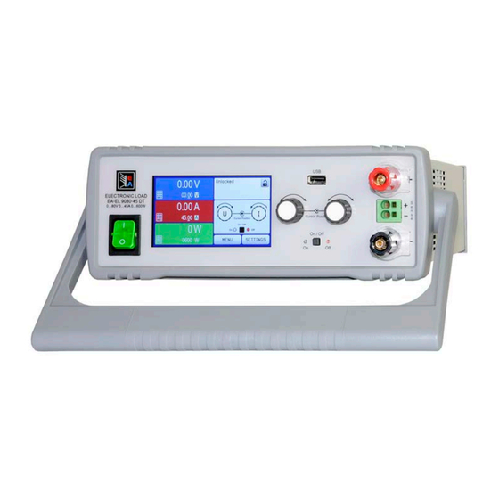
EL 9000 DT Series 1.8.4 Views Figure 1 - Front side Figure 2 - Back side A - Power switch E - Remote sensing input B - Control panel F - Remote control interfaces (digital, analog) C - Front USB port (type A) - Page 93 EL 9000 DT Series Figure 3 - Side view from left, horizontal position Figure 4 - Top view EA Elektro-Automatik GmbH Fon: +49 2162 / 3785-0 www.elektroautomatik.de Page 15 Helmholtzstr. 31-37 • 41747 Viersen Fax: +49 2162 / 16230 ea1974@elektroautomatik.de...
-
Page 94: Control Elements
EL 9000 DT Series 1.8.5 Control elements Figure 5 - Control Panel Overview of the elements of the operating panel For a detailed description see section „1.9.5. The control panel (HMI)“ and „1.9.5.2. Rotary knobs“. Touchscreen display Used for selection of set values, menus, display of actual values and status. -
Page 95: Construction And Function
1.9.1 General description The conventional, electronic DC loads of the EL 9000 DT series are especially suitable for research laboratories, test applications or educational , all due to their compact construction in a rugged desktop enclosure. Apart from basic functions of electronic loads, set point curves can be generated in the integrated function gen- erator (sine, rectangular, triangular and other curve types). -
Page 96: The Control Panel (Hmi)
EL 9000 DT Series 1.9.5 The control panel (HMI) The HMI (Human Machine Interface) consists of a display with touchscreen, two rotary knobs, a button and an USB port. 1.9.5.1 Touchscreen display The graphic touchscreen display is divided into a number of areas. The complete display is touch sensitive and can be operated by finger or stylus to control the equipment. - Page 97 EL 9000 DT Series • Status display (upper right) This area displays various status texts and symbols: Display Description Locked The HMI is locked Unlocked The HMI is unlocked Remote: The device is under remote control from..Analog ..the built-in analog interface ..the built-in USB port...
- Page 98 EL 9000 DT Series 1.9.5.4 Resolution of the displayed values In the display, set values can be adjusted with a fixed step width. The number of decimal places depends on the device model. The values have 4 or 5 digits. Actual and set values always have the same number of digits.
-
Page 99: Usb Port (Back Side)
USB stick and installs a virtual COM port. Details for remote control can be found on the web site of Elektro-Automatik or on the included USB stick. The device can be addressed via this port either using the international standard ModBus RTU protocol or by SCPI language. -
Page 100: Installation & Commissioning
2.3.2 Preparation Mains connection with an EL 9000 DT series device is done via the included 1.5 meters long 3 pole mains cord. Dimensioning of the DC wiring to the source has to reflect the following: • The cable cross section should always be specified for at least the maximum current of the device. - Page 101 EL 9000 DT Series 2.3.3.1 The handle The included handle is not only used to carry the device, it can also uplift the device’s front for easier access to knobs and buttons or better display readability. The handle can be rotated into various positions in an angle of 300°, such as a variable position (60...150°), 0°, -45°, -90°...
- Page 102 EL 9000 DT Series Standing surface (handle in -45° position) 2.3.3.3 Installation in a 19” system The optionally available 2U mounting frame (see 1.9.4) can be used to install the power supply in a 19” cabinet or other 19” related system with at least 2U of space. The frame will center the device horizontally on the front plate of the frame.
- Page 103 EL 9000 DT Series Figure 7 - Removal of the front and rear frame Figure 8 - Assembly steps for the mounting frame EA Elektro-Automatik GmbH Fon: +49 2162 / 3785-0 www.elektroautomatik.de Page 25 Helmholtzstr. 31-37 • 41747 Viersen Fax: +49 2162 / 16230 ea1974@elektroautomatik.de...
- Page 104 EL 9000 DT Series Figure 9 - Positions for the hex spacers (3) Figure 10 - Rear view after complete assembly of the mounting frame Figure 11 - Front view after complete assembly of the mounting frame EA Elektro-Automatik GmbH Fon: +49 2162 / 3785-0 www.elektroautomatik.de...
-
Page 105: Connection To Dc Sources
EL 9000 DT Series 2.3.4 Connection to DC sources • When using any model which is rated for 40 A or higher current, attention has to be paid to where the load is connected on the DC input terminals. The front-side 4mm connection point is only rated for max. -
Page 106: Connecting The Analog Interface
EL 9000 DT Series Figure 12 - Example for remote sensing wiring The connector Sense is a clamp terminal. It means for the remote sensing cables: • Insert cables: crimp sleeves onto the cable ends and simply push them into the bigger square hole • Remove cables: use a small flat screwdriver and push into the smaller square hole next to the bigger one to... -
Page 107: Initial Commission
EL 9000 DT Series 2.3.9 Initial commission For the first start-up after purchasing and installing the device, the following procedures have to be executed: • Confirm that the connection cables to be used are of a satisfactory cross section! • Check if the factory settings of set values, safety and monitoring functions and communication are suitable for your intended application of the device and adjust them if required, as described in the manual! • In case of remote control via PC, read the additional documentation for interfaces and software! -
Page 108: Operation And Application
EL 9000 DT Series Operation and application Personal safety • In order to guarantee safety when using the device, it is essential that only persons operate the device who are fully acquainted and trained in the required safety measures to be taken when working with dangerous electrical voltages • For models which accept dangerous voltages, a protection against unwanted physical contact... -
Page 109: Current Regulation / Constant Current / Current Limitation
EL 9000 DT Series 3.2.2 Current regulation / constant current / current limitation Current regulation is also known as current limitation or constant current mode (CC) and is fundamental to the normal operation of an electronic load. The DC input current is held at a predetermined level by varying the internal resistance according to Ohm’s law R = U / I such that, based on the input voltage, a constant current flows. -
Page 110: Dynamic Characteristics And Stability Criteria
EL 9000 DT Series See the diagrams below for clarification. Principle derating progression, depicted on the models of the 1300W 1200 W power class. Peak power The peak power is absorbed by the load device for a time x, 1000W until derating starts. -
Page 111: Alarm Conditions
EL 9000 DT Series Alarm conditions This section only gives an overview about device alarms. What to do in case your device indi- cates an alarm condition is described in section „3.6. Alarms and monitoring“. As a basic principle, all alarm conditions are signalled optically (text + message in the display), acoustically (if activated) and as a readable status and alarm counter via the digital interface. -
Page 112: Manual Operation
EL 9000 DT Series Manual operation 3.4.1 Powering the device The device should, as far as possible, always be switched on using the toggle switch on the front of the device. After switching on, the display will first show the company logo, followed by a language selection which will close automatically after 3 seconds and later manufacturer’s name and address, device type, firmware version(s), serial... - Page 113 EL 9000 DT Series EA Elektro-Automatik GmbH Fon: +49 2162 / 3785-0 www.elektroautomatik.de Page 35 Helmholtzstr. 31-37 • 41747 Viersen Fax: +49 2162 / 16230 ea1974@elektroautomatik.de Germany...
- Page 114 EL 9000 DT Series EA Elektro-Automatik GmbH Fon: +49 2162 / 3785-0 www.elektroautomatik.de Page 36 Helmholtzstr. 31-37 • 41747 Viersen Fax: +49 2162 / 16230 ea1974@elektroautomatik.de Germany...
- Page 115 EL 9000 DT Series EA Elektro-Automatik GmbH Fon: +49 2162 / 3785-0 www.elektroautomatik.de Page 37 Helmholtzstr. 31-37 • 41747 Viersen Fax: +49 2162 / 16230 ea1974@elektroautomatik.de Germany...
- Page 116 EL 9000 DT Series 3.4.3.1 Menu “General Settings” Setting P. Description Allow remote control Selection “NO” means that the device cannot be remotely controlled over either the digital or analog interfaces. If remote control is not allowed, the status will be shown as “Local”...
- Page 117 EL 9000 DT Series 3.4.3.2 Menu “User Events” See „3.6.2.1 User defined events“ on page 52. 3.4.3.3 Menu “Profiles” See „3.9 Loading and saving a user profile“ on page 54. 3.4.3.4 Menu “Overview” This menu page displays an overview of the set values (U, I, P or U, I, P, R) and alarm settings as well as adjust- ment limits.
- Page 118 EL 9000 DT Series Submenu “Ethernet” Element Description Host name Configure the host name for the device here for the use with a local DNS entry Domain name Configure the domain name for the device here for the use with a local DNS entry TCP Keep-Alive Default setting: disabled Enables/disables the “keep-alive”...
-
Page 119: Adjustment Limits
EL 9000 DT Series 3.4.4 Adjustment limits Adjustment limits are only effective on the related set values, no matter if using manual adjust- ment or remote control! Defaults are, that all set values (U, I, P, R) are adjustable from 0 to 102%. -
Page 120: Manual Adjustment Of Set Values
EL 9000 DT Series 3.4.6 Manual adjustment of set values The set values for voltage, current, power and resistance are the fundamental operating possibilities of an elec- tronic load and hence the two rotary knobs on the front of the device are always assigned to two of the four values in manual operation. -
Page 121: The Meter Bars
EL 9000 DT Series Limitations of the alternative status page: • Set and actual values of power and resistance are not displayed and the set values are only indirectly accessible • No access to the settings overview (MENU button) while the DC input is on In alternative status page mode, the set values of power and resistance are not adjustable while the DC input is switched on. -
Page 122: Recording To Usb Stick (Logging)
EL 9000 DT Series 3.4.10 Recording to USB stick (logging) Device data can be recorded to USB stick (2.0 / 3.0 may work, but not all vendors are supported) anytime. For specifications of the USB stick and the generated log files refer to section „1.9.5.5. USB-Port (Front side)“. -
Page 123: Remote Control
Programming details for the interfaces, the communication protocols etc. are to be found in the documentation “Programming Guide ModBus RTU & SCPI“ which is supplied on the included USB stick or which is available as download from the EA Elektro-Automatik website. EA Elektro-Automatik GmbH Fon: +49 2162 / 3785-0 www.elektroautomatik.de... -
Page 124: Remote Control Via The Analog Interface (Ai)
EL 9000 DT Series 3.5.4 Remote control via the analog interface (AI) 3.5.4.1 General The built-in, galvanically isolated, 15-pole analog interface (short: AI) is on the back side of the device offers the following possibilities: • Remote control of current, voltage, power and resistance • Remote status monitoring (CC/CP, CV) - Page 125 EL 9000 DT Series 3.5.4.3 Acknowledging device alarms Device alarms (see 3.6.2) are always indicated in the front display and some of them are also reported as signal on the analog interface socket (see table below). In case of a device alarm occurring during remote control via analog interface, the DC input will be switched off the same way as in manual control.
- Page 126 EL 9000 DT Series 3.5.4.5 Overview of the Sub-D Socket 3.5.4.6 Simplified diagram of the pins Digital Input (DI) Analog Input (AI) It requires to use a switch with low resist- High resistance input (impedance V~0.5 ance (relay, switch, circuit breaker etc.) in >40 k..100 kΩ) for an OA circuit.
- Page 127 EL 9000 DT Series • Remote control is not active In this mode of operation pin “REM-SB” can serve as lock, preventing the DC input from being switched on by any means. This results in following possible situations: Parameter Behaviour input „REM-SB“...
-
Page 128: Alarms And Monitoring
EL 9000 DT Series Alarms and monitoring 3.6.1 Definition of terms There is a clear distinction between equipment alarms (see „3.3. Alarm conditions“) such as overvoltage or over- heating, and user defined events such as e.g OVD overvoltage monitoring. Whilst device alarms primarily serve to protect the source by switching off the DC input, user defined events can also switch off the DC input (Action = ALARM), but can also simply give an acoustic signal to make the user aware. - Page 129 EL 9000 DT Series Some device alarms are configurable: Alarm Meaning Description Range Indication OverVoltage Triggers an alarm if the DC input voltage reaches the Display, analog & 0 V...1.03*U Protection defined threshold. The DC input will be switched off..
- Page 130 EL 9000 DT Series 3.6.2.1 User defined events The monitoring functions of the device can be configured for user defined events. By default, events are deactivated (action = NONE). Contrary to device alarms, the events only work while the DC input is switched on. It means, for instance, that you cannot detect undervoltage (UVD) anymore after switching the DC input off and the voltage is still sinking.
-
Page 131: Control Panel (Hmi) Lock
EL 9000 DT Series Control panel (HMI) lock In order to avoid the accidental alteration of a value during manual operation, the rotary knobs or the touchscreen can be locked so that no alteration of values will be accepted without prior unlocking. -
Page 132: Loading And Saving A User Profile
EL 9000 DT Series Loading and saving a user profile The menu “Profiles” serves to select between a default profile and up to 5 user profiles. A profile is a collection of all settings and set values. Upon delivery, or after a reset, all 6 profiles have the same settings and all set values are 0. -
Page 133: The Function Generator
EL 9000 DT Series 3.10 The function generator 3.10.1 Introduction The built-in function generator (short: FG) is able to create various signal forms and apply these to the set value of voltage or current. The standard functions are based on an arbitrary generator and directly accessible and configurable using manual control. -
Page 134: Method Of Operation
EL 9000 DT Series 3.10.3 Method of operation In order to understand how the function generator works and how the value settings interact, the following should be noted: The device operates always with the three set values U,I and P, also in function generator mode. -
Page 135: Sine Wave Function
EL 9000 DT Series Because the DC input is automatically switched on in order to settle the start situation, the static values are effective to the source immediately after loading the function. These static values represent the situation before start and after the end of the function, so it doesn’t need to start from 0. -
Page 136: Triangular Function
EL 9000 DT Series 3.10.6 Triangular function The following parameters can be configured for a triangular wave function: Value Range Description I(A), U(A) 0...(Nominal value - (Off)) of U, I A = Amplitude of the signal to be generated I(Off), U(Off) 0...(Nominal value - (A)) of U, I Off = Offset, based on the foot of the triangular wave 0.01 ms...36000 s... -
Page 137: Trapezoidal Function
EL 9000 DT Series 3.10.8 Trapezoidal function The following parameters can be configured for a trapezoidal curve function: Value Range Description I(A), U(A) 0...(Nominal value - (Off)) of U, I A = Amplitude of the signal to be generated I(Off), U(Off) 0...(Nominal value - (A)) of U, I... -
Page 138: 3.10.10 Arbitrary Function
EL 9000 DT Series 3.10.10 Arbitrary function The arbitrary (freely definable) function offers the user further scope. There are 99 sequence points are available for use for current I and voltage U, all of which have the same parameters but which can be differently configured so that a complex function process can be built up. - Page 139 EL 9000 DT Series Schematic diagram: Applications and results: Example 2 Focussing 1 cycle of 1 sequence point from 99: The DC values at start and end are the same but the AC (amplitude) not. The end value is higher than the start so that the amplitude increases with each new half sine wave continuously through the se- quence point.
- Page 140 EL 9000 DT Series By linking together a number of differently configured sequence points, complex progressions can be created. Smart configuration of the arbitrary generator can be used to match triangular, sine, rectangular or trapezoidal wave func- tions and thus, e.g. a sequence of rectangular waves with differing amplitudes or duty cycles could be produced.
- Page 141 EL 9000 DT Series 3.10.10.1 Loading and saving the arbitrary function The 99 sequence points of the arbitrary function, which can be manually configured with the control panel of the device and which are applicable either to voltage (U) or current (I), can be saved to or loaded from a common USB stick via the front side USB port.
-
Page 142: 3.10.11 Ramp Function
EL 9000 DT Series ► How to save a sequence point table to an USB stick: Do not plug the USB stick yet or remove it. Access the function selection menu of the function generator via MENU -> Function Generator -> Arbitrary... - Page 143 EL 9000 DT Series When discharging with high currents, compared to the nominal battery capacity and in dynamic mode, it may hap- pen that the battery voltage shortly drops below the U-DV threshold and the test will unintentionally stop. Here it is recommended to adjust U-DV accordingly.
- Page 144 EL 9000 DT Series 3.10.12.4 Displayed values During the test run, the display will show a set of values and status: • Actual battery voltage on the DC input in V • Actual discharge current in A • Actual power in W • Discharge voltage U...
-
Page 145: 3.10.13 Mpp Tracking Function
EL 9000 DT Series 3.10.13 MPP tracking function MPP stands for the maximum power point (see principle view to the right) on the power curve of solar panels. Solar inverters, when connected to such panels, constantly track this MPP once it has been found. -
Page 146: 3.10.14 Remote Control Of The Function Generator
EL 9000 DT Series Following parameters can be configured for tracking mode MPP2: Value Range Description 0...Nominal value of U Voltage of the solar panel when unloaded, taken from the panel specs 0...Nominal value of I Short-circuit current, max. specified current of the solar panel Δt... -
Page 147: Other Applications
EL 9000 DT Series 3.11 Other applications 3.11.1 Series connection Series connection is not a permissible operating method for electronic loads and must not be installed or operated under any circumstances! 3.11.2 Parallel operation Multiple devices of same kind and ideally same model can be connected in parallel in order to create a system with higher total current and hence higher power. -
Page 148: Service And Maintenance
Contact the supplier in case of suspicion and elicit the steps to be taken. It will then usually be necessary to return the device to Elektro-Automatik (with or without warranty). If a return for checking or repair is to be carried out, ensure that: • the supplier has been contacted and it is clarified how and where the equipment should be sent. -
Page 149: Calibration
EL 9000 DT Series Calibration 4.3.1 Preface The devices of series EL 9000 DT feature a function to re-adjust the most important input related values when doing a calibration and in case these values have moved out of tolerance. The re-adjustment is limited to compensate small differences of up to 1% or 2% of the max. - Page 150 EL 9000 DT Series 4.3.3.1 Set values ► How to calibrate the voltage Adjust the connected voltage source to approx. 102% of the maximum voltage specified for the EL device. For the example with an 80 V EL this would be 81.6 V for the source. Set the current limitation of the voltage source to >5% of the nominal current specified for EL device, for this...
-
Page 151: Contact And Support
Contact and support Repairs Repairs, if not otherwise arranged between supplier and customer, will be carried out by EA Elektro-Automatik. For this the equipment must generally be returned to the manufacturer. No RMA number is needed. It is sufficient to package the equipment adequately and send it, together with a detailed description of the fault and, if still under guarantee, a copy of the invoice, to the following address. - Page 154 EA-Elektro-Automatik GmbH & Co. KG Development - Production - Sales Helmholtzstraße 31-37 41747 Viersen Germany Fon: +49 2162 / 37 85-0 Telefax: +49 2162 / 16 230 ea1974@elektroautomatik.de www.elektroautomatik.de Distributed by: dataTec ▪ Ferdinand-Lassalle-Str. 52 ▪ 72770 Reutlingen ▪ Tel. 07121 / 51 50 50 ▪ Fax 07121 / 51 50 10 ▪ info@datatec.de ▪ www.datatec.de...
Need help?
Do you have a question about the EL 9000 DT Series and is the answer not in the manual?
Questions and answers