
Related Manuals for Elektro-Automatik ELR 10000 4U


Summary of Contents for Elektro-Automatik ELR 10000 4U
- Page 1 Operating Guide ELR 10000 4U Electronic DC Load with Energy Recovery Doc ID: ELR1EN Revision: 01 Date: 01/2020...
-
Page 3: Table Of Contents
ELR 10000 4U Series TABLE OF CONTENTS GENERAL About this document ........5 2.3.4 Connection to AC supply ......34 1.1.1 Retention and use ..........5 2.3.5 Connection to DC loads or DC sources ..37 1.1.2 Copyright ............5 2.3.6 Connection of remote sense .......38 1.1.3... - Page 4 ELR 10000 4U Series 3.8 Locking the “Limits” and “Profiles” ....65 3.9 Loading and saving user profiles ....66 3.10 The function generator.........67 3.10.1 Introduction...........67 3.10.2 General ............67 3.10.3 Method of operation ........68 3.10.4 Manual operation .........68 3.10.5 Sine wave function ........69 3.10.6 Triangular function ........70 3.10.7 Rectangular function ........70 3.10.8 Trapezoidal function ........71 3.10.9 DIN 40839 function ........71...
-
Page 5: General
Symbol for general safety notices (instructions and damage protection bans) or important infor- mation for operation Symbol for general notices Warranty EA Elektro-Automatik guarantees the functional competence of the applied technology and the stated performance parameters. The warranty period begins with the delivery of free from defects equipment. Terms of guarantee are included in the general terms and conditions (TOS) of EA Elektro-Automatik. Limitation of liability All statements and instructions in this manual are based on current norms and regulations, up-to-date technology and our long term knowledge and experience. -
Page 6: Disposal Of Equipment
ELR 10000 4U Series Disposal of equipment A piece of equipment which is intended for disposal must, according to European laws and regulations (ElektroG, WEEE) be returned to the manufacturer for scrapping, unless the person operating the piece of equipment or an- other, delegated person is conducting the disposal. Our equipment falls under these regulations and is accordingly... -
Page 7: Safety
ELR 10000 4U Series Safety 1.7.1 Safety notices Mortal danger - Hazardous voltage • Never touch AC cables or connectors directly after unplugging from mains supply as the danger of electric shock remains! • There can be dangerous potential between DC minus to PE or DC plus to PE due to charged X capacitors, even when the DC input has been disconnected from the sour. -
Page 8: Responsibility Of The User
ELR 10000 4U Series 1.7.2 Responsibility of the user The equipment is in industrial operation. Therefore the operators are governed by the legal safety regulations. Alongside the warning and safety notices in this manual the relevant safety, accident prevention and environmental regulations must also be applied. -
Page 9: Alarm Signals
ELR 10000 4U Series 1.7.5 Alarm signals The equipment offers various possibilities for signaling alarm conditions, however, not for danger situations. The signals may be optical (on the display as text), acoustic (piezo buzzer) or electronic (pin/status output of an analog interface). All alarms will cause the device to switch off the DC input. The meaning of the signals is as follows: Signal OT • Overheating of the device • DC input will be switched off (OverTemperature) • Non-critical Signal OVP / SOVP • Overvoltage shutdown of the DC input due to high voltage entering the device or gen-... -
Page 10: Specific Technical Data (Standard 400/480 V Models)
ELR 10000 4U Series 1.8.3 Specific technical data (standard 400/480 V models) Model 400/480 V 30 kW ELR 10060-1000 ELR 10080-1000 ELR 10200-420 AC supply Voltage range (L-L) 380 / 400 / 480 V, ±10% Frequency 45 - 66 Hz Connection 3ph, PE Leak current ≤ 3.5 mA Phase current Max. 56 A Efficiency of energy recovery ≤ 94% ≤ 94%... - Page 11 ELR 10000 4U Series Model 400/480 V 30 kW ELR 10060-1000 ELR 10080-1000 ELR 10200-420 Analog interface Signals See “3.5.4.3. Analog interface specification” Galvanic isolation to the device Max. 725 V DC Sample rate of inputs & outputs 500 Hz Insulation Allowed potential shift (floating voltage) on the DC output: Negative DC to PE ±500 V DC...
- Page 12 ELR 10000 4U Series Model 400/480 V 30 kW ELR 10360-240 ELR 10500-180 ELR 10750-120 AC supply Voltage range (L-L) 380 / 400 / 480 V, ±10% Frequency 45 - 66 Hz Connection 3ph, PE Leak current ≤ 3.5 mA Phase current Max. 56 A Efficiency of energy recovery ≤ 94.6% ≤ 95.3% ≤ 95.5% Power factor ≈ 0.99 DC input Max. voltage U...
- Page 13 ELR 10000 4U Series Model 400/480 V 30 kW ELR 10360-240 ELR 10500-180 ELR 10750-120 Analog interface Signals See “3.5.4.3. Analog interface specification” Galvanic isolation to the device Max. 1500 V DC Sample rate of inputs & outputs 500 Hz Insulation Allowed potential shift (floating voltage) on the DC output: Negative DC to PE ±1500 V DC...
- Page 14 ELR 10000 4U Series Model 400/480 V 30 kW ELR 11000-80 ELR 11500-60 ELR 12000-40 AC supply Voltage range (L-L) 380 / 400 / 480 V, ±10% Frequency 45 - 66 Hz Connection 3ph, PE Leak current ≤ 3.5 mA Phase current Max. 56 A Efficiency of energy recovery ≤ 94.6% ≤ 95.3% ≤ 95.5% Power factor ≈ 0.99 DC input Max. voltage U...
- Page 15 ELR 10000 4U Series Model 400/480 V 30 kW ELR 11000-80 ELR 11500-60 ELR 12000-40 Analog interface Signals See “3.5.4.3. Analog interface specification” Galvanic isolation to the device Max. 1500 V DC Sample rate of inputs & outputs 500 Hz Insulation Allowed potential shift (floating voltage) on the DC output: Negative DC to PE ±1500 V DC...
-
Page 16: Specific Technical Data (208 V Models)
ELR 10000 4U Series 1.8.4 Specific technical data (208 V models) The so-called 208 V models, designated on the type label as “US208V”, are derivations from the standard models, intended to be sold on the US or Japan market or places where 208 V three-phase supply is typical. They only differ in a few technical specifications which are listed below. The remaining specifications are listed in 1.8.3. The differences compared to the standard models are in the AC supply and DC power rating. Model 208 V 15 kW ELR 10060-1000 US208V ELR 10080-1000 US208V ELR 10200-420 US208V AC supply Voltage range (L-L), 187...228 V AC Connection 3ph, PE DC input Max. power P... -
Page 17: Views
ELR 10000 4U Series 1.8.5 Views EA Elektro-Automatik GmbH Fon: +49 2162 / 3785-0 www.elektroautomatik.com Page 17 Helmholtzstr. 31-37 • 41747 Viersen Fax: +49 2162 / 16230 ea1974@elektroautomatik.com Germany... - Page 18 ELR 10000 4U Series EA Elektro-Automatik GmbH Fon: +49 2162 / 3785-0 www.elektroautomatik.com Page 18 Helmholtzstr. 31-37 • 41747 Viersen Fax: +49 2162 / 16230 ea1974@elektroautomatik.com Germany...
- Page 19 ELR 10000 4U Series EA Elektro-Automatik GmbH Fon: +49 2162 / 3785-0 www.elektroautomatik.com Page 19 Helmholtzstr. 31-37 • 41747 Viersen Fax: +49 2162 / 16230 ea1974@elektroautomatik.com Germany...
- Page 20 ELR 10000 4U Series EA Elektro-Automatik GmbH Fon: +49 2162 / 3785-0 www.elektroautomatik.com Page 20 Helmholtzstr. 31-37 • 41747 Viersen Fax: +49 2162 / 16230 ea1974@elektroautomatik.com Germany...
- Page 21 ELR 10000 4U Series EA Elektro-Automatik GmbH Fon: +49 2162 / 3785-0 www.elektroautomatik.com Page 21 Helmholtzstr. 31-37 • 41747 Viersen Fax: +49 2162 / 16230 ea1974@elektroautomatik.com Germany...
- Page 22 ELR 10000 4U Series Figure 6 - Top view (example with DC terminal type 1 and water cooling installed) EA Elektro-Automatik GmbH Fon: +49 2162 / 3785-0 www.elektroautomatik.com Page 22 Helmholtzstr. 31-37 • 41747 Viersen Fax: +49 2162 / 16230 ea1974@elektroautomatik.com Germany...
-
Page 23: Control Elements
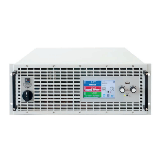
ELR 10000 4U Series 1.8.6 Control elements Figure 7- Control Panel Overview of the elements on the control panel For a detailed description see section “1.9.6. The control panel (HMI)”. Touchscreen display Used for selection and adjustment of set values, call of menus, as well as display of actual values and status. -
Page 24: Construction And Function
Construction and function 1.9.1 General description The devices of series ELR 10000 4U are energy recovering, switching electronic loads. The recovery or recuperation feature inverts the consumed DC energy with an efficiency of up to 95.5% and feeds it back into the local mains. Apart from basic functions of electronic loads, set point curves can be generated by the integrated function gen- erator (sine, rectangular, triangular and other curve types). Arbitrary generator curves (99 points) can be saved to... -
Page 25: Scope Of Delivery
ELR 10000 4U Series 1.9.3 Scope of delivery 1 x Electronic load device 2 x Remote sensing plugs 1 x 1.8 m (5.9 ft) USB cable 1 x Set of DC terminal covers (only with models from 360 V) 1 x Cover for remote sensing (Sense) terminals 1 x USB stick with documentation and software 1 x AC connector plug (clamp type) 1.9.4 Accessories For these devices the following hardware accessories are available:... -
Page 26: The Control Panel (Hmi)
ELR 10000 4U Series 1.9.6 The control panel (HMI) The HMI (Human Machine Interface) consists of a display with touchscreen, two rotary knobs, a pushbutton and an USB port. 1.9.6.1 Touchscreen display The graphic touchscreen display is divided into a number of areas. The complete display is touch sensitive and can be operated by finger or stylus to control the equipment. - Page 27 ELR 10000 4U Series • Status display (upper right) This area displays various status texts and symbols: Display Description The HMI is locked The HMI is unlocked Remote: The device is under remote control from..Analog ...the built-in analog interface Ethernet ...the built-in Ethernet interface USB & others ...the built-in USB port or a plug in interface module Local The device has been locked by the user explicitly against remote control Alarm: Alarm condition which has not been acknowledged or still exists.
- Page 28 ELR 10000 4U Series 1.9.6.4 Resolution of the displayed values In the display, set values can be adjusted in fixed increments. The number of decimal places depends on the device model. The values have 4 or 5 digits. Actual and set values always have the same number of digits. Adjustment resolution and number of digits of set values in the display:...
-
Page 29: Usb Port (Rear Side)
ELR 10000 4U Series 1.9.7 USB port (rear side) The USB port on the rear side of the device is provided for communication with the device and for firmware updates. The included USB cable can be used to connect the device to a PC (USB 2.0 or 3.0). The driver is delivered with the device and installs a virtual COM port. Details about remote control can be found in form of a programming guide on the included USB stick or on the web site of the manufacturer. -
Page 30: Share Bus" Connector
ELR 10000 4U Series 1.9.10 “Share BUS” connector The two BNC sockets (50 Ω type) labeled “Share BUS” form a digital, passed- through Share bus. This bus is bidirectional and connects the bus master unit via “Share BUS Output” to the next slave unit (“Share BUS Input”) etc., for use in parallel operation, also called master-slave. BNC cables of suitable length can be obtained from us or electronics stores. Share bus operation requires to connect only identical device models. Follow- ing power supply and electronic load series are compatible on this Share bus: • PSB 10000... -
Page 31: Ethernet Port
ELR 10000 4U Series 1.9.13 Ethernet port The RJ45 LAN/Ethernet port on the rear side of the device is provided for communication with the device in terms of remote control or monitoring. The user basically has two options of access: 1. A website (HTTP, port 80) which is accessible in a standard browser via the... -
Page 32: Installation & Commissioning
ELR 10000 4U Series Installation & commissioning Transport and storage 2.1.1 Transport • The handles on the front and rear side of the device are not for carrying! • Because of its weight, transport by hand should be avoided where possible. If unavoidable then only the housing should be held and not on the exterior parts (handles, DC terminal, rotary knobs). -
Page 33: Preparation
ELR 10000 4U Series 2.3.2 Preparation Mains connection is done via the included 5 pole plug and on the back of the device. Wiring of the plug is at least 4 wire (3x L, PE) of suitable cross section and length. Full configuration with all phases, PE and N is permissible. For recommendations for a cable cross section see “2.3.4. Connection to AC supply”. Dimensioning of the DC wiring to the source has to reflect the following: • The cable cross section should always be specified for at least the maximum current of the device. • Continuous operation at the approved limit generates heat which must be removed, as well as voltage loss which depends on cable length and heating. -
Page 34: Connection To Ac Supply
ELR 10000 4U Series 2.3.4 Connection to AC supply • Connection to an AC supply must only be carried out by qualified personnel and the device must always be run directly on a power grid (transformer are permitted) and not on generators or UPS equipment! • Cable cross section must be suitable for the maximum input current of the device! See tables below. The device should furthermore be fused externally and according to the current rating and cable cross section • Before plugging the AC plug ensure that the device is switched off by its mains switch! - Page 35 ELR 10000 4U Series Figure 9 - Example for an AC cable with 5 conductors (european color code, cable not included in delivery) 2.3.4.2 Models for 208 V The so-called US208V models are also delivered with a 5 pole AC plug. This plug is connected to 3-phase AC supply, according to the labeling next the plug (filter housing). Required are following phases: Rated power Inputs on AC plug Supply type Configuration 15 kW L1, L2, L3, (N), PE Three-phase (3P) Delta The PE conductor is imperative and must always be wired! The N conductor, if present in the cable, can be wired to the free slot on the AC plug.
- Page 36 ELR 10000 4U Series 2.3.4.3 Installation concept for energy recovering devices An ELR 10000 device converts the consumed DC energy into AC and feeds it back into the local power grid. The generated current adds to the grid current (see schematic below) and this can lead to an overload of the existing electrics installation. Considering any two outlets, no matter of what kind they are, there is usually no extra fusing installed in between. In case of a defect in the AC part (i.e. short-circuit) of any consumer device or when there are...
-
Page 37: Connection To Dc Loads Or Dc Sources
ELR 10000 4U Series 2.3.5 Connection to DC loads or DC sources • In the case of a device with a high nominal DC current and hence a thick and heavy DC connection cable it’s necessary to take account of the weight of the cable and the strain imposed on the DC connection. -
Page 38: Connection Of Remote Sense
ELR 10000 4U Series Examples of the type 1 terminal: • 90° up or down • space saving in depth • no bending radius • horizontal lead • space saving in height • large bending radius 2.3.6 Connection of remote sense • Remote sensing is only effective during constant voltage operation (CV) and for other regulation... -
Page 39: Grounding Of The Dc Input
ELR 10000 4U Series 2.3.7 Grounding of the DC input Grounding one of the DC input poles is permissible, but causes potential shift against PE on the opposite pole. Because of insulation, there is a max. allowed potential shift defined for the DC terminal poles, which depends on the device model. Refer to “1.8.3. Specific technical data (standard 400/480 V models)” for details. -
Page 40: Connecting The Share Bus
Connecting the Share bus The “Share BUS” connectors on the rear side (2x BNC type) can be used to connect to the Share bus of further units of series ELR 10000 4U. The main purpose of the Share bus is to balance the voltage of multiple units in parallel operation, especially when using the integrated function generator of the master unit. For further information about parallel operation refer to section “3.11.1. -
Page 41: Operation And Application
ELR 10000 4U Series Operation and application Important notes 3.1.1 Personal safety • In order to guarantee safety when using the device, it’s essential that only persons operate the device who are fully acquainted and trained in the required safety measures to be taken when working with dangerous electrical voltages • Read and follow all safety warnings in section 1.7.1! -
Page 42: Current Regulation / Constant Current / Current Limiting
ELR 10000 4U Series 3.2.2 Current regulation / constant current / current limiting Current regulation is also known as current limiting or constant current mode (CC). The current in the DC input of the device is held constant once the current consumed by the load reaches the adjusted limit. Then the device automatically switches to CC. -
Page 43: Alarm Conditions
ELR 10000 4U Series Alarm conditions This section only gives an overview about device alarms. What to do in case your device indi- cates an alarm condition is described in section “3.6. Alarms and monitoring”. As a basic principle, all alarm conditions are signaled optically (text + message in the display) and acoustically (if activated), as well as status via digital interface. In addition, the alarms are reported as signals on the analog interface. For later acquisition, an alarm counter can also be shown on display or read via digital interface. -
Page 44: Manual Operation
ELR 10000 4U Series Manual operation 3.4.1 Switching on the device The device should, as far as possible, always be switched on using the rotary switch on the front of the device. Alternatively this can take place using an external cutout (contactor, circuit breaker) of suitable current capacity. After switching on, the display will first show some device related information (model, firmware versions etc.) and then a language selection screen for 3 seconds. A few seconds later it will show the main screen. - Page 45 ELR 10000 4U Series 3.4.3.1 Sub menu “Settings” This sub menu can be accessed directly from the main screen by tapping the Settings button. Group Parameters & description Presets U, I, P, R Presetting of all set values via on-screen numeric pad. Protection OVP, OCP, OPP Adjust the thresholds of the protections Limits U-max, U-min etc.
- Page 46 ELR 10000 4U Series Group Parameters & description Analog interface Pin 14 Pin 14 of the analog interface (see section 3.5.4.3) is by default assigned to only signal the device alarm OVP. This parameter allows to also enable signaling the device alarms OCP and OPP in 7 possible combinations: Alarm OVP •...
- Page 47 ELR 10000 4U Series Group Parameters & description Master-slave Mode Selecting “Master” or “Slave” enables the master-slave mode (MS) and defines the position for the unit in the MS system. For details see section “3.11.1. Parallel operation in master-slave (MS)””. Termination resistor Activates or deactivates the so-called bus termination of the digital master-slave bus via a switchable resistor. Termination should be activation if required, usually when problems with the master-slave bus operation occur. Bias resistors Additionally to the regular termination resistor there are two bias resistor to be activated if re- quired to help stabilize the bus further.
- Page 48 ELR 10000 4U Series 3.4.3.2 Sub menu “Profiles” See “3.9 Loading and saving user profiles” on page 66. 3.4.3.3 Sub menu “Overview” This menu page displays an overview of the set values (U, I, P or U, I, P, R), device alarm thresholds, event set- tings, adjustment limits, as well as an alarm history which lists the number of device alarms that occurred since the device has been powered.
- Page 49 ELR 10000 4U Series IF Settings Description Node Address Selection of the Profibus or node address of the device within range 1...125 via direct input Function Tag String input box for a user-definable text which describes the Profibus slave function tag. Max. length: 32 characters Location Tag String input box for a user-definable text which describes the Profibus slave location tag. Max. length: 22 characters Installation Date String input box for a user-definable text which describes the Profibus slave instal- lation date tag. Max. length: 40 characters Description String input box for a user-definable text which describes the Profibus slave. Max. length: 54 characters...
- Page 50 ELR 10000 4U Series IF Settings Description Baud rate Setup of the CAN bus speed or baud rate in typical value between 10 kbps and 1Mbps. Default: 500 kbps ID Format Selection of the CAN ID format and range between Standard (11 Bit ID, 0h...7ffh) and Extended (29 Bit, 0h...1fffffffh) Termination Activates or deactivates CAN bus termination with a built-in resistor.
- Page 51 ELR 10000 4U Series Group Parameters & description Timeouts TCP keep-alive Activates keep-alive network functionality for the Ethernet port, which is used to keep the socket connection open. As long as keep-alive is valid in the network, the device will disable the Ethernet timeout. Also see below at “Timeout ETH”. Timeout USB/RS232 Defines the max. time between two subsequent bytes or blocks of a transferred message. For more information about the timeout refer to the external programming documentation “Programming ModBus & SCPI”. Default value: 5...
-
Page 52: Adjustment Limits
ELR 10000 4U Series 3.4.4 Adjustment limits Adjustment limits are only effective on the related set values, no matter if using manual adjust- ment or remote control setting! Defaults are that all set values (U, I, P, R) are adjustable from 0 to 102%. The full range may be obstructive in some cases, espe- cially for protection of applications against overvoltage. Therefore upper and lower limits for current (I) and voltage (U) can be set separately, which then limit the range of the adjustable set values. For power (P) and resistance (R) only upper value limits can be set. -
Page 53: Manual Adjustment Of Set Values
ELR 10000 4U Series 3.4.6 Manual adjustment of set values Adjusting set values for current, power and resistance are the fundamental operating possibilities of an electronic load and hence in manual operation the two rotary knobs on the front of the device are always assigned to two of the values. -
Page 54: Switching The Dc Input On Or Off
ELR 10000 4U Series 3.4.7 Switching the DC input on or off The DC input of the device can be manually or remotely switched on and off. Switching the DC input on during manual operation or digital remote control can be disabled by pin REM-SB of the built-in analog interface. For more information refer to 3.4.3.1 and example a) in 3.5.4.7. -
Page 55: The Quick Menu
ELR 10000 4U Series 3.4.8.3 USB logging file format Type: text file in german/european or US american CSV format (depending on the selected setting) Layout: Legend: U set / I set / P set / R set: Set values U, I, P and R U actual / I actual / P actual / R actual: Actual values Output/Input: State of the DC input Device mode: Actual regulation mode (also see “3.2. -
Page 56: The Graph
ELR 10000 4U Series Tapping a button activates and then deactivates the function again. Buttons with black on white indicate an acti- vated feature: Symbol Belongs to Meaning USB logging is running (the symbols is only available when USB logging USB logging has been activated in menu “Settings”) Master-slave... -
Page 57: Remote Control
ELR 10000 4U Series Remote control 3.5.1 General Remote control is possible via one of the built-in interfaces (analog, USB, Ethernet) or via one of the optional in- terface modules. Important here is that only the analog or one digital interface can be in control. One of the digital ones is the master-slave bus. It means that if an attempt was made to switch to remote control via the digital interface whilst analog remote control is active (pin REMOTE = LOW) the device would report an error via the digital interface. In the opposite... -
Page 58: Remote Control Via The Analog Interface
ELR 10000 4U Series 3.5.4 Remote control via the analog interface 3.5.4.1 General The built-in, galvanically isolated, 15-pole analog interface, below referenced in short form as AI, is located on the rear side of the device offers the following possibilities: • Remote control of current, voltage, power and resistance • Remote status monitoring (CV, DC input) • Remote alarm monitoring (OT, OVP, PF, OCP, OPP) • Remote monitoring of actual values • Remote on/off switching of the DC input Setting the three set values of voltage, current and power via the analog interface must always be done concur- rently. - Page 59 ELR 10000 4U Series 3.5.4.3 Analog interface specification Pin Name Type* Description Default levels Electrical specifications 0…10 V or. 0...5 V correspond Accuracy 0-5 V range: < 0.4% ***** 1 VSEL Voltage set value to 0..100% of U Accuracy 0-10 V range: < 0.2% ***** 0…10 V or. 0...5 V correspond 2 CSEL Current set value Input impedance R >40 k...100 k...
- Page 60 ELR 10000 4U Series 3.5.4.5 Overview of the D-sub socket 3.5.4.6 Simplified diagram of the pins Digital Input (DI) Analog Input (AI) It requires to use a switch with low resis- High resistance input (impedance V~0.5 tance (relay, switch, circuit breaker etc.) in >40 kΩ) for an operation amplifier order to send a clean signal to the DGND.
- Page 61 ELR 10000 4U Series • Remote control has not been activated In this mode of operation pin REM-SB can serve as lock, preventing the DC input from being switched on by any means. This results in following possible situations: Level on Parameter pin „REM- „REM-SB Behavior terminal SB“ Level“ The DC input isn’t locked. It can be switched on by pushbutton...
-
Page 62: Alarms And Monitoring
ELR 10000 4U Series Alarms and monitoring 3.6.1 Definition of terms There is a clear distinction between device alarms (see “3.3. Alarm conditions”), such as overvoltage protection OVP or overheating protection, and user defined events such as OVD (overvoltage detection). Whilst device alarms only switch off the DC input, user defined events can do more. They can also switch off the DC input (Action = Alarm), but can alternatively simply give an acoustic signal to make the user aware. The actions driven by user... - Page 63 ELR 10000 4U Series These device alarms can’t be configured and are based on hardware: Short Long Description Indication AC supply over- or undervoltage. Triggers an alarm if the AC supply is out of specification or when the device is cut from supply, for exam- Power Fail ple when switching it off with the power switch. The DC input will be Display, analog & switched off. digital interfaces OverTem- Triggers an alarm if the internal temperature reaches a certain limit. perature The DC input will be switched off. Triggers an alarm if the master unit loses contact to any slave unit. The Master-Slave DC input will be switched off. The alarm can be cleared by reinitializing...
- Page 64 ELR 10000 4U Series 3.6.2.1 User defined events The monitoring functions of the device can be configured for user defined events. By default, events are deacti- vated (Action set to None). Contrary to device alarms, the events only work while the DC input is switched on. It means, for instance, that you cannot detect undervoltage (UVD) anymore after switching the DC input off and the source lower it. The following events can be configured independently: Event Meaning Description Range Triggers an event if the DC voltage falls below the de- UnderVoltage Detection 0 V...U...
-
Page 65: Locking The Control Panel (Hmi)
ELR 10000 4U Series Locking the control panel (HMI) In order to avoid the accidental alteration of a value during manual operation the rotary knobs or the touchscreen can be locked so that no alteration of values will be accepted without prior unlocking. -
Page 66: Loading And Saving User Profiles
ELR 10000 4U Series Loading and saving user profiles The menu “Profiles” serves to select between a default profile and up to 5 user profiles. A profile is a collection of all settings and set values. Upon delivery or after a factory reset all 6 profiles have the same settings and all set values are 0. Values adjusted on the main screen or anywhere else belong to a working profile which can be saved to one of the 5 user profiles. These user profiles or the default profile can then be switched. The default profile is read-only. The purpose of a profile is to load a set of set values, settings limits and monitoring thresholds quickly without having to readjust these. As all HMI settings are saved in the profile, including language, a profile change can also be accompanied by a change in HMI language. On calling up the menu page and selecting a profile the most important settings can be seen, but not changed. ► How to save the current values and settings as a user profile: While the DC input is switched off, tap touch area on the main screen. -
Page 67: The Function Generator
ELR 10000 4U Series 3.10 The function generator 3.10.1 Introduction The built-in function generator (short: FG) is able to create various signal forms and apply these to the set value of either voltage or current. The standard functions are based on an arbitrary generator and directly accessible and configurable using man- ual control. -
Page 68: Method Of Operation
ELR 10000 4U Series 3.10.3 Method of operation In order to understand how the function generator works and how the value settings interact, the following should be noted: The device operates always with the three set values U,I and P, also in function generator mode. -
Page 69: Sine Wave Function
ELR 10000 4U Series Setting the various functions and their parameters is described below. After the function generator screen has been reached, the function is ready to run. Before and while the function is running, some global and also some function related values can be adjusted anytime. -
Page 70: Triangular Function
ELR 10000 4U Series 3.10.6 Triangular function The following parameters can be configured for a triangular function: Parameter Range Description Amplitude (A) 0...(rated value - |Offs|) of U or I Amplitude of the signal to be generated Offset (O) 0... (U - A) or 0...(I - A) Offset, based on the foot of the triangular wave Time t1 0.1 ms...36,000,000 ms Rising edge time Δt of the triangular wave signal Time t2 0.1 ms...36,000,000 ms Falling edge time Δt of the triangular wave signal Schematic diagram: Application and result: A triangular wave signal for use on the current or voltage is generated. -
Page 71: Trapezoidal Function
ELR 10000 4U Series 3.10.8 Trapezoidal function The following parameters can be configured for a trapezoidal function: Parameter Range Description Amplitude (A) 0...(rated value - |Offs|) of U or I Amplitude of the signal to be generated Offset (O) 0... (U - A) or 0...(I - A) Offset, based on the foot of the trapezium Time t1 0.1 ms...36,000,000 ms Time for the positive slope of the trapezoidal wave signal. -
Page 72: Arbitrary Function
ELR 10000 4U Series 3.10.10 Arbitrary function The arbitrary (freely definable) function or function generator offers the user a wider scope of options. There are 99 curve segments (here: sequence points) available for use on either current (I) or voltage (U), all of which have the same set of parameters but can be differently configured, so that a complex function curve can be “constructed”. An arbitrary number out of the 99 sequence points can run in a sequence point block and this block can then be repeated up to 999 times or infinitely. Since the function must be assigned to either current or voltage, mix assign- ments of sequence point to both isn’t possible. - Page 73 ELR 10000 4U Series Schematic diagram: Applications and results: Example 2 Focusing 1 cycle of 1 sequence point: The DC values at start and end are the same but those of the am- plitude aren’t. The end value is higher than the start value so the amplitude increases with each new half sine wave continuously over the sequence point time.
- Page 74 ELR 10000 4U Series By linking together a number of differently configured sequence points, complex progressions can be created. Smart configuration of the arbitrary generator can be used to match triangular, sine, rectangular or trapezoidal wave func- tions and thus, e.g. a sequence of rectangular waves with differing amplitudes or duty cycles could be produced. Schematic diagram: Applications and results: Example 7 Focusing 2 cycles of 1 sequence point: One sequence point, configured as in example 3, is run. Since the settings define that the end offset (DC) is higher than the start, the second run will revert to the same start level as the first, regardless of the signal level at the end of the first run. This can produce a discontinuity in the total progression (marked in red) which may only be compensated with a careful choice of settings.
- Page 75 ELR 10000 4U Series Column Connected to HMI parameter Range AC start See table in “3.10.10. Arbitrary function” AC end See table in “3.10.10. Arbitrary function” Start frequency 0...10000 Hz End frequency 0...10000 Hz Angle 0...359° DC start See table in “3.10.10. Arbitrary function” DC end See table in “3.10.10.
-
Page 76: Ramp Function
ELR 10000 4U Series 3.10.11 Ramp function The following parameters can be configured for a ramp function: Parameter Range Description Start 0...U or 0...I Start/end point of the ramp. Both values can be equal or different, which then results in either a rising, falling or horizontal ramp Time t1 0.1 ms...36,000,000 ms Time before ramp-up or ramp-down of the signal. Time t2 0.1 ms...36,000,000 ms Ramp-up or ramp-down time 10 h after reaching the ramp end, the function will stop automatically (i.e. I = 0 A, in case the ramp was assigned to the current), unless it has been stopped manually before. - Page 77 ELR 10000 4U Series 3.10.12.1 Loading IU tables from USB stick The so-called IU tables can be loaded from a file via a standard USB stick that is formatted in FAT32. In order to load the file, it has to meet following specifications: • The file name always begins with IU (not case-sensitive) • The file must be a text file of type Excel CSV and must only contain one column with exactly 4096 values without gaps • Values with decimal places must use decimal separator that matches the selection in the general setting “Log file separator format”, which also defines the decimal separator between dot and comma (US default should be dot) • No value may exceed the nominal value of the device.
-
Page 78: Battery Test Function
ELR 10000 4U Series 3.10.13 Battery test function The purpose of the battery test function is to discharge various battery types in industrial product tests or laboratory applications. Due to the nature of an electronic it can only work in sink mode, it means only discharge the battery. - Page 79 ELR 10000 4U Series 3.10.13.3 Stop conditions These parameters are valid for all test modes and define additionally stop conditions: Value Range Description Discharge end voltage 0...U Threshold (in Volt) to stop discharging Action: Ah limit None, Signal, Enables the optional stop condition End of test Discharge capacity 0...99999.99 Ah Threshold for the max. capacity to consume from or feed to the bat- tery and after which the test can stop automatically.
-
Page 80: Mpp Tracking Function
ELR 10000 4U Series 3.10.13.6 Possible reasons for battery test stop The battery test function run can be stopped by different reasons: • Manual stop on the HMI with button “Stop” • After the max. test time has been reached and action “End of test” was set for it • After the max. battery capacity to consume has been reached and action “End of... - Page 81 ELR 10000 4U Series 3.10.14.2 Mode MPP2 This mode tracks the MPP, so it’s closest to the operation of a real solar inverter. Once the MPP is found, the function won’t stop, but try to track the MPP permanently. Due to the nature of solar panels this can only be done below the level of the MPP. As soon as this point is reached, the voltage starts to sink further and so does the actual power. The additional parameter ΔP defines how much the power may fall before the direction is reversed and the voltage starts to rise again until the load reaches the MPP. The result are...
- Page 82 ELR 10000 4U Series 3.10.14.5 Load curve data from USB stick for mode MPP4 Curve point data (only one voltage value per point), in form of a CSV file, is loaded from USB stick. See section 1.9.6.5 for the naming convention. Contrary to manual adjustment where you can define and use an arbitrary num- ber of points, loading from USB requires the CSV file to always contain the full number of points (100), because it can’t define which one is start and end. However, the on-screen setting for Start and End point remain valid. It means, if you actually want to use all 100 points from your loaded curve, you must set the parameters according.
-
Page 83: Remote Control Of The Function Generator
ELR 10000 4U Series 3.10.15 Remote control of the function generator The function generator can be remotely controlled, but configuration and control of the functions with individual commands is different from manual operation. The external documentation “Programming Guide ModBus & SCPI” on the included USB stick explains the approach. In general the following items apply: • The function generator isn’t directly controllable via the analog interface; the only impact to the function run can come from pin REM-SB switching the DC input off and on, which will also stop and restart the function • The function generator is unavailable if R mode (resistance) is activated... -
Page 84: Other Applications
ELR 10000 4U Series 3.11 Other applications 3.11.1 Parallel operation in master-slave (MS) Multiple devices of same kind and model can be connected in parallel in order to create a system with higher total current and hence higher power. For parallel operation in master-slave mode the units are usually connected on their DC inputs, their Share bus ports and their master-slave bus ports. This bus is digital and makes the system work as one big unit regarding value adjustment, readings and all further control. The Share bus is intended to balance the units dynamically in their voltage and also thus current on the DC input, especially if the master unit runs a dynamic function. - Page 85 ELR 10000 4U Series A max. of 64 units can be connected via Share bus. 3.11.1.4 Wiring and set-up of the digital master-slave bus The master-slave connectors are built-in and can be connected via network cables (≥CAT3, patch cable). After this, MS can be configured manually or by remote control. The following applies: • A maximum of 64 units can be connected via the bus: 1 master and up to 63 slaves.
- Page 86 ELR 10000 4U Series ► Step 2: Configuring the master unit While the DC terminal is switched off, tap on in the main screen to access the Settings menu. Swipe up to find group “Master-slave” and tap it. Tapping on the blue button text next to Mode will open a selector. By selecting Master, if not already set, the master-slave mode is activated and the device is defined as master.
-
Page 87: Series Connection
ELR 10000 4U Series 3.11.1.7 Alarms and other problem situations Master-slave operation, due to the connection of multiple units and their interaction, can cause additional problem situations which do not occur when operating individual units. For such occurrences the following regulations have been defined: • Generally, if the master loses connection to any slave, it will generate an MSP (master-slave protection) alarm, pop up a message on the screen and switch off its DC input. The slaves will fall back to single operation mode and also switch off their DC input. The MSP alarm can be deleted by initializing the master-slave system again. This can be done either in the MSP alarm pop-up screen or in the MENU of the master or via remote control. Alternatively, the alarm is also cleared by deactivating master-slave on the master unit • If one or more slave units are cut from AC supply (power switch, blackout, supply undervoltage) and come back later, they’re not automatically initialized and included again in the MS system. Then the init has to be repeated. • If the master unit is cut from AC supply (power switch, blackout) and comes back later, the unit will automati- cally initialize the MS system again, finding and integrating all active slaves. In this case, MS can be restored automatically. -
Page 88: Service And Maintenance
ELR 10000 4U Series Service and maintenance Maintenance / cleaning The device needs no recurring maintenance. Cleaning may be needed for the internal fans, the frequency of cleanse is depending on the ambient conditions. The fans serve to cool the components which are heated by the inherent power loss. Heavily dirt filled fans can lead to insufficient airflow and therefore the DC input would switch... -
Page 89: Calibration
ELR 10000 4U Series Calibration 4.3.1 Preface The devices of series ELR 10000 don’t have a built- in feature to re-adjust the most important DC input related values, but they can still be readjusted using the software EA Power Control. The required calibration app is in- cluded in the free of charge base version of this software. In order to use the feature is may be necessary to install a n update of this software. -
Page 90: Contact And Support
ELR 10000 4U Series Contact and support General Repairs, if not otherwise arranged between supplier and customer, will be carried out by the manufacturer. For this the device must generally be returned to the manufacturer. No RMA number is needed. It’s sufficient to package the equipment adequately and send it, together with a detailed description of the fault and, if still under guarantee, a copy of the invoice, to the following address. - Page 92 EA Elektro-Automatik GmbH & Co. KG Development - Production - Sales Helmholtzstraße 31-37 41747 Viersen Germany Fon: +49 2162 / 37 85-0 Mail: ea1974@elektroautomatik.com Web: www.elektroautomatik.com...
Need help?
Do you have a question about the ELR 10000 4U and is the answer not in the manual?
Questions and answers