Table of Contents

Subscribe to Our Youtube Channel
Related Manuals for Elektro-Automatik EL 9000 B 15U


Summary of Contents for Elektro-Automatik EL 9000 B 15U
- Page 1 Operating Guide EL 9000 B 15U/24U Electronic DC load Attention! This document is only valid for devices with TFT Doc ID: EL9B15EN display and firmware “KE: 2.31”, “HMI: 2.20” and “DR: 1.6.6” or Revision: 03 higher. Date: 05/2021...
-
Page 3: Table Of Contents
EL 9000 B 15U/24U Series TABLE OF CONTENTS GENERAL About this document ........5 2.3.8 Connection of remote sense .......30 1.1.1 Retention and use ..........5 2.3.9 Installation of an interface module ....31 1.1.2 Copyright ............5 2.3.10 Connecting the analog interface ....31 1.1.3... - Page 4 EL 9000 B 15U/24U Series 3.10 The function generator.........60 3.10.1 Introduction...........60 3.10.2 General ............60 3.10.3 Method of operation ........61 3.10.4 Manual operation .........61 3.10.5 Sine wave function ........62 3.10.6 Triangular function ........63 3.10.7 Rectangular function ........63 3.10.8 Trapezoidal function ........64 3.10.9 DIN 40839 function ........64...
-
Page 5: General
EA Elektro-Automatik guarantees the functional competence of the applied technology and the stated performance parameters. The warranty period begins with the delivery of free from defects equipment. Terms of guarantee are included in the general terms and conditions (TOS) of EA Elektro-Automatik. Limitation of liability All statements and instructions in this manual are based on current norms and regulations, up-to-date technology and our long term knowledge and experience. -
Page 6: Disposal Of Equipment
EL 9000 B 15U/24U Series Disposal of equipment A piece of equipment which is intended for disposal must, according to European laws and regulations (ElektroG, WEEE) be returned to the manufacturer for scrapping, unless the person operating the piece of equipment or an- other, delegated person is conducting the disposal. -
Page 7: Safety
EL 9000 B 15U/24U Series Safety 1.7.1 Safety notices Mortal danger - Hazardous voltage • Electrical equipment operation means that some parts can be under dangerous voltage. Therefore all parts under voltage must be covered! • All work on DC connections must be carried out under zero voltage, i.e. DC input not connected to a source and may only be performed by qualified and informed persons. -
Page 8: Responsibility Of The User
EL 9000 B 15U/24U Series 1.7.2 Responsibility of the user The equipment is in industrial operation. Therefore the operators are governed by the legal safety regulations. Alongside the warning and safety notices in this manual the relevant safety, accident prevention and environmental regulations must also be applied. -
Page 9: Alarm Signals
EL 9000 B 15U/24U Series 1.7.5 Alarm signals The equipment offers various possibilities for signalling alarm conditions, however, not for danger situations. The signals may be optical (on the display as text), acoustic (piezo buzzer) or electronic (status output pin of an analog interface). - Page 10 EL 9000 B 15U/24U Series Global Voltage regulation Accuracy (at 23 ± 5°C) < 0.1% U Load regulation at ΔI < 0.05% U Display: Resolution See section „1.9.6.4. Resolution of the displayed values“ Display: Accuracy ≤ 0.1% U Remote sensing compensation Max.
- Page 11 EL 9000 B 15U/24U Series Model 15 U cabinet EL 9080-1530 B EL 9200-630 B EL 9360-360 B EL 9500-270 B EL 9750-180 B Default assembly 3 units 3 units 3 units 3 units 3 units AC inrush current @ 230 V ≤ 207 A ≤...
- Page 12 EL 9000 B 15U/24U Series Model 24 U cabinet EL 9080-2550 B EL 9200-1050 B EL 9360-600 B EL 9500-450 B EL 9750-300 B Default assembly 5 units 5 units 5 units 5 units 5 units AC inrush current @ 230 V ≤ 345 A ≤...
-
Page 13: Views
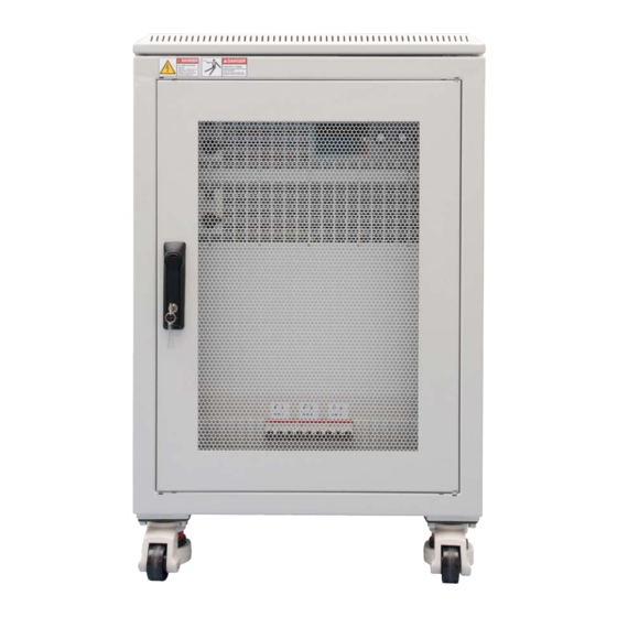
EL 9000 B 15U/24U Series 1.8.4 Views Figure 1 - Front side (example model in 15U) A - Power switch B - Control panel EA Elektro-Automatik GmbH Fon: +49 2162 / 3785-0 www.elektroautomatik.de Page 13 Helmholtzstr. 31-37 • 41747 Viersen Fax: +49 2162 / 16230 ea1974@elektroautomatik.de... - Page 14 EL 9000 B 15U/24U Series Figure 2 - Rear side (example model in 15U) D - Digital and analog interfaces E - Share Bus and remote sensing connection F - DC input G - AC input connection of the single units...
- Page 15 EL 9000 B 15U/24U Series Not included by default Figure 4 - Rear side (example model in 24 U) Figure 3 - Front side (example model in 24U with optional emergency off switch) EA Elektro-Automatik GmbH Fon: +49 2162 / 3785-0 www.elektroautomatik.de...
- Page 16 EL 9000 B 15U/24U Series EA Elektro-Automatik GmbH Fon: +49 2162 / 3785-0 www.elektroautomatik.de Page 16 Helmholtzstr. 31-37 • 41747 Viersen Fax: +49 2162 / 16230 ea1974@elektroautomatik.de Germany...
-
Page 17: Control Elements
EL 9000 B 15U/24U Series 1.8.5 Control elements Figure 7- Control Panel Overview of the elements on the control panel For a detailed description see section „1.9.6. The control panel (HMI)“. Touchscreen display Used for adjustment of set values, setup in menus, as well as display of actual values and status. -
Page 18: Construction And Function
General description The electronic DC loads of the EL 9000 B 15U and EL 9000 B 24U series have been designed for industrial high current and high power demands. Configured as mobile 19” cabinets in either 15 or 24 units of height they allow for operation in many different situations, such as high current battery or motor tests. -
Page 19: Scope Of Delivery
EL 9000 B 15U/24U Series 1.9.3 Scope of delivery 1 x Electronic load cabinet with 2-6 installed PSI 9000 3U units 1 x 1.8 m USB cable 1 x USB stick with documentation and software (for the cabinet, further USB sticks from the power module may be included) 1.9.4... -
Page 20: The Control Panel (Hmi)
EL 9000 B 15U/24U Series 1.9.6 The control panel (HMI) The HMI (Human Machine Interface) consists of a display with touchscreen, two rotary knobs, a pushbutton and an USB port. 1.9.6.1 Touchscreen display The graphic touchscreen display is divided into a number of areas. The complete display is touch sensitive and can be operated by finger or stylus to control the equipment. - Page 21 EL 9000 B 15U/24U Series • Status display (upper right) This area displays various status texts and symbols: Display Description Locked The HMI is locked Unlocked The HMI is unlocked Remote: The device is under remote control from..Analog ..the built-in analog interface USB &...
- Page 22 EL 9000 B 15U/24U Series 1.9.6.4 Resolution of the displayed values In the display, set values can be adjusted in fixed increments. The number of decimal places depends on the device model. The values have 4 or 5 digits. Actual and set values always have the same number of digits.
-
Page 23: Usb Port Type B (Rear Side)
EL 9000 B 15U/24U Series 1.9.7 USB port type B (rear side) The USB-B port on the rear side of the topmost unit (master) is provided for communication with the device and for firmware updates of the master. For the other units (slaves) in the cabinet, firmware updates are applied via the particular USB port of the units. -
Page 24: Share Bus Connector
EL 9000 B 15U/24U Series 1.9.10 Share bus connector This 2 pole WAGO connector “Share” on the rear side of the units is used by the master to balance the DC power consumption between all units. It must not be connected externally or used in a different way and must always remain plugged at all units to ensure safe and proper operation of the electronic load cabinet. -
Page 25: Installation & Commissioning
EL 9000 B 15U/24U Series Installation & commissioning Transport and storage 2.1.1 Transport • The handles on the front side of the units are not for carrying, but only for insertion into or removal from the cabinet! • Because of the weight of the units, transport by hand should be avoided where possible. If unavoidable then only the housing should be held and not on the exterior parts (handles, DC input terminal, rotary knobs). -
Page 26: Installing The Device
EL 9000 B 15U/24U Series 2.3.3 Installing the device • Select the location for the device so that the connection to the source is as short as possible • Leave sufficient space behind the equipment for ventilation, at least 50 cm • Never place the cabinet’s rear in front of flammable material (wood, paper, fabric, plastic etc.),... -
Page 27: Connection To Ac Supply
EL 9000 B 15U/24U Series 2.3.4 Connection to AC supply • Connection to an AC mains supply must only be carried out by qualified personnel! • Cable cross section must be suitable for the maximum input current of the device (see table below)! • Before plugging in the input plug ensure that the device is switched off by its mains switch! -
Page 28: Connection To Dc Sources
EL 9000 B 15U/24U Series 2.3.5 Connection to DC sources The DC input is located on the rear side of the cabinet and is not protected by any kind of fuse. The cross section of the connection cables is determined by the DC current consumption, cable length and ambient temperature. - Page 29 EL 9000 B 15U/24U Series 2.3.5.1 Connection points Every cabinet has bus bars on the DC input, which have 3 or 6 connection points on their lower end. Each con- nection point can be used to screw one or two cables. The table in section 2.3.5 lists the number and size of the connection points for every rated input current and power.
-
Page 30: Grounding Of The Dc Input
EL 9000 B 15U/24U Series 2.3.6 Grounding of the DC input The device’s DC input can always be grounded on the minus pole, i.e. can be directly connected to PE. The DC plus pole, however, if it’s to be grounded, may only be so for input voltages up to 400 V, because the potential of the minus pole is shifted into negative direction by the value of the input voltage. -
Page 31: Installation Of An Interface Module
EL 9000 B 15U/24U Series 2.3.9 Installation of an interface module The optionally obtainable interface modules can be retrofitted by the user and are exchangeable with each other. The settings for the currently installed module vary and need to be checked and, if necessary, corrected on initial installation and after module exchange. -
Page 32: Initial Commission
EL 9000 B 15U/24U Series 2.3.12 Initial commission For the first start-up after installation of the cabinet, the following procedures have to be executed: • Confirm that the connection cables to be used are of a satisfactory cross section! • Check if the factory settings of set values, safety and monitoring functions and communication are suitable for your intended application of the device and adjust them if required, as described in the manual! • Before using remote control via PC, read the additional documentation for interfaces and software! -
Page 33: Adding New Units
EL 9000 B 15U/24U Series 2.3.16 Adding new units Some models have a spare position for another slave unit to install later in order to extend the total power. The new slave unit can be purchased and delivered separately and installed on location. See „1.9.4. Accessories“ for details. -
Page 34: Operation And Application
EL 9000 B 15U/24U Series Operation and application Personal safety • In order to guarantee safety when using the device, it’s essential that only persons operate the device who are fully acquainted and trained in the required safety measures to be taken when working with dangerous electrical voltages • For models which can generate a voltage which is dangerous by contact, or is connected to... -
Page 35: Current Regulation / Constant Current / Current Limiting
EL 9000 B 15U/24U Series 3.2.2 Current regulation / constant current / current limiting Current regulation is also known as current limitation or constant current mode (CC) and is fundamental to the normal operation of an electronic load. The DC input current is held at a predetermined level by varying the internal resistance according to Ohm’s law R = U / I such that, based on the input voltage, a constant current flows. -
Page 36: Dynamic Characteristics And Stability Criteria
EL 9000 B 15U/24U Series See the diagrams below for clarification. Principle derating progression, depicted on the example of one load unit. All models of this series have multiple load units Peak power equipped which not necessarily start derating at the same time. -
Page 37: Alarm Conditions
EL 9000 B 15U/24U Series Alarm conditions This section only gives an overview about device alarms. What to do in case your device indi- cates an alarm condition is described in section „3.6. Alarms and monitoring“. As a basic principle, all alarm conditions are signaled optically (text + message in the display), acoustically (if activated), via the digital interface, plus also as status on the analog interface. -
Page 38: Manual Operation
EL 9000 B 15U/24U Series Manual operation 3.4.1 Switching on the device The cabinets of this series are master-slave systems with one master unit and up to 5 slave units. In order for the master to find and initialise the slaves the fastest way after powering the cabinet, it should be powered last. - Page 39 EL 9000 B 15U/24U Series 3.4.3.1 Menu “General Settings” Setting Description Allow remote control Selection No means that the device can’t be remotely controlled over either the digital or analog interfaces. If remote control isn’t allowed, the status will be shown as Local in the status area on the main display.
- Page 40 EL 9000 B 15U/24U Series Setting Description Enable R mode Activates (Yes) or deactivates (No) the internal resistance control. If activated, the resistance set value of the simulated internal resistor can be adjusted additionally to the other set values. For details refer to „3.2.3. Resistance regulation / constant resistance“...
- Page 41 EL 9000 B 15U/24U Series IF Level 1 Description Node Address Selection of the Profibus or node address of the device within range 1...125 via direct input Function Tag String input box for a user-definable text which describes the Profibus slave function tag.
- Page 42 EL 9000 B 15U/24U Series IF Level 1 Description Host name Free choice of host name (default: Client) Domain name Free choice of Domain (default: Workgroup) Function Tag String input box for a user-definable text which describes the Profinet slave function tag.
- Page 43 EL 9000 B 15U/24U Series Element Description Com Timeout Timeout USB/RS232 [ms] Default value: 5, range: 5...65535 ms Defines the max. time between two subsequent bytes or blocks of a transferred message. For more information refer to the external programming documentation “Programming Guide ModBus &...
- Page 44 EL 9000 B 15U/24U Series Element Description Status page Enables/disables two display related options for the main screen with actual and set values: Show meter bar: in U/I/P mode, i. e. resistance mode not activated, a meter bar for 0-100% actual values of voltage, current and power is shown.
-
Page 45: Adjustment Limits
EL 9000 B 15U/24U Series 3.4.4 Adjustment limits Adjustment limits are only effective on the related set values, no matter if using manual adjust- ment or remote control! Defaults are that all set values (U, I, P, R) and the corresponding ad- justment limits are adjustable from 0 to 102%. -
Page 46: Manual Adjustment Of Set Values
EL 9000 B 15U/24U Series 3.4.6 Manual adjustment of set values The set values for voltage, current, power and resistance are the fundamental operating possibilities of an elec- tronic load and hence the two rotary knobs on the front of the device are always assigned to two of the four values in manual operation. -
Page 47: The Meter Bars
EL 9000 B 15U/24U Series Limitations of the alternative status page: • Set and actual values of power are not displayed and the set value of power is only indirectly accessible • Set value of resistance isn’t displayed and only indirectly accessible • No access to the settings overview (MENU button) while the DC input is on... -
Page 48: Recording To Usb Stick (Logging)
EL 9000 B 15U/24U Series 3.4.10 Recording to USB stick (logging) Device data can be recorded to USB stick (2.0 / 3.0 may work, but not all vendors are supported) anytime. For specifications of the USB stick and the generated log files refer to section „1.9.6.5. USB port (front side)“. -
Page 49: Remote Control
EL 9000 B 15U/24U Series Remote control 3.5.1 General In this cabinet device, remote control is only considered for the master unit. Slave unit can only be monitored, by any available interface. Remotely controlling the master is possible via its built-in analog or USB port or via one of the optional interface modules (IF-AB series). - Page 50 EL 9000 B 15U/24U Series 3.5.3.2 General information about the interface modules The master unit in the cabinet can have one of the plug-in and retrofittable modules listed in 3.5.3.1 installed. It can take over remote control of the device alternatively to the built-in USB type B on the rear side or analog interface.
-
Page 51: Remote Control Via The Analog Interface (Ai)
EL 9000 B 15U/24U Series 3.5.4 Remote control via the analog interface (AI) 3.5.4.1 General The built-in, galvanically isolated, 15-pole analog interface (short: AI) is on the rear side of the device offers the following possibilities: • Remote control of current, voltage, power and resistance • Remote status monitoring (CV, DC input on/off) - Page 52 EL 9000 B 15U/24U Series 3.5.4.4 Analog interface specification Pin Name Type* Description Default levels Electrical specifications 0…10 V or. 0...5 V corre- 1 VSEL Set voltage value Accuracy 0-5 V range: < 0.4% ***** spond to 0..100% of U Accuracy 0-10 V range: <...
- Page 53 EL 9000 B 15U/24U Series 3.5.4.6 Simplified diagram of the pins Digital Input (DI) Analog Input (AI) V~0.5 The DI is internally pulled up and thus it re- High resistance input (impedance quires to use a contact with low resistance >40 k...
- Page 54 EL 9000 B 15U/24U Series In case the DC input is already switched on, toggling the pin will switch the DC input off, similar to what it does in analog remote control: Parameter Level on „Analog Behavior input interface REM-SB Rem-SB“...
-
Page 55: Alarms And Monitoring
EL 9000 B 15U/24U Series Alarms and monitoring 3.6.1 Definition of terms There is a clear distinction between device alarms (see „3.3. Alarm conditions“), such as overvoltage protection, and user defined events such as OCD (overcurrent detection). Whilst device alarms primarily serve to protect the connected DC source by switching the DC input off, user defined events can do the same (Action = ALARM), but can also simply give an acoustic signal to make the user aware. - Page 56 EL 9000 B 15U/24U Series These device alarms can’t be configured and are based on hardware: Short Long Description Indication AC supply over- or undervoltage. Triggers an alarm if the AC supply is out of specification or when the device is cut from supply, for example Display, analog &...
- Page 57 EL 9000 B 15U/24U Series 3.6.2.1 User defined events The monitoring functions of the device can be configured for user defined events. By default, events are deactivated (Action = NONE). Contrary to device alarms, the events only work while the DC input is switched on. It means, for instance, that you can’t detect undervoltage (UVD) anymore after switching the DC input off, while the voltage...
-
Page 58: Control Panel (Hmi) Lock
EL 9000 B 15U/24U Series Control panel (HMI) lock In order to avoid the accidental alteration of a value during manual operation the rotary knobs or the touchscreen can be locked so that no alteration of values will be accepted without prior unlocking. -
Page 59: Loading And Saving A User Profile
EL 9000 B 15U/24U Series Loading and saving a user profile The menu “Profiles” serves to select between a default profile and up to 5 user profiles. A profile is a collection of all settings and set values. Upon delivery, or after a reset, all 6 profiles have the same settings and all set values are 0. -
Page 60: The Function Generator
EL 9000 B 15U/24U Series 3.10 The function generator 3.10.1 Introduction The built-in function generator (short: FG) is able to create various signal forms and apply these to the set value of voltage or current. In manual operation, all generator functions are available for access on the front panel. In remote control, only the customizable arbitrary generator and a XY function are available. -
Page 61: Method Of Operation
EL 9000 B 15U/24U Series 3.10.3 Method of operation In order to understand how the function generator works and how the value settings interact, the following should be noted: The device always operates with the three set values U,I and P, also in function generator mode. -
Page 62: Sine Wave Function
EL 9000 B 15U/24U Series ► How to load a function After setting the values for the required signal generation, tap on the touch area The device will then load the data into the internal controller and changes the display. Shortly afterwards the static values are set... -
Page 63: Triangular Function
EL 9000 B 15U/24U Series 3.10.6 Triangular function The following parameters can be configured for a triangular wave function: Value Range Description I(A), U(A) 0...(Nominal value - (Off)) of U, I A = Amplitude of the signal to be generated I(Off), U(Off) 0...(Nominal value - (A)) of U, I... -
Page 64: Trapezoidal Function
EL 9000 B 15U/24U Series 3.10.8 Trapezoidal function The following parameters can be configured for a trapezoidal curve function: Value Range Description I(A), U(A) 0...(Nominal value - (Off)) of U, I A = Amplitude of the signal to be generated I(Off), U(Off) 0...(Nominal value - (A)) of U, I... -
Page 65: Arbitrary Function
EL 9000 B 15U/24U Series 3.10.10 Arbitrary function The arbitrary, i. e. freely definable function offers the user a wider scope. There are 99 freely configurable sequence points available. While all have the same set of parameters, they can be configured differently so that a complex function process can be created. - Page 66 EL 9000 B 15U/24U Series Schematic diagram: Applications and results: Example 2 Focusing 1 cycle of 1 sequence point: The DC values at start and end are the same but the AC (amplitude) not. The end value is higher than the start so that the amplitude increases with each new half sine wave continuously through the sequence point.
- Page 67 EL 9000 B 15U/24U Series By linking together a number of differently configured sequence points, complex progressions can be created. Smart configuration of the arbitrary generator can be used to match triangular, sine, rectangular or trapezoidal wave func- tions and thus, e.g. a sequence of rectangular waves with differing amplitudes or duty cycles could be produced.
- Page 68 EL 9000 B 15U/24U Series 3.10.10.1 Loading and saving the arbitrary function The 99 points of the arbitrary function, which can be manually configured with the control panel of the device and which are applicable either to voltage (U) or current (I), can be saved to or loaded from a common USB stick via the front side USB port.
-
Page 69: Ramp Function
EL 9000 B 15U/24U Series ► How to save a sequence point table to an USB stick: Do not plug the USB stick yet or remove it. Access the function selection menu of the function generator via MENU -> Function Generator -> Arbitrary... - Page 70 EL 9000 B 15U/24U Series Uploading of a table from an USB stick must use text files in CSV format (.csv). Plausibility is checked on loading (values not too high, number of values correct),and possible errors reported in which case the table will not be loaded.
-
Page 71: Battery Test Function
EL 9000 B 15U/24U Series 3.10.13 Battery test function The purpose of the battery test function is to discharge various battery types in industrial product tests or labora- tory applications. It’s only available via access on the HMI, at least as setup and use are described below, but can also be achieved in remote control using the arbitrary function generator. - Page 72 EL 9000 B 15U/24U Series 3.10.13.3 Other parameters These parameters are separately adjustable in each battery test mode. Parameter Range Description Discharge voltage 0...Nominal value of U Variable voltage threshold to make the test stop when reached (is connected to the battery voltage on the DC input of the load) Discharge time 0...10 h...
-
Page 73: Mpp Tracking Function
EL 9000 B 15U/24U Series 3.10.13.6 Possible reasons for a battery test stop The battery test function run can stop or be stopped by different reasons: • Manual stop on the HMI with touch area STOP • After the max. test time has been reached and action End of test was set for it • After the max. - Page 74 EL 9000 B 15U/24U Series 3.10.14.2 Mode MPP2 This mode tracks the MPP, so it’s closest to the operation of a solar inverter. Once the MPP is found, the function won’t stop, but try to track the MPP permanently. Due to the nature of solar panels this can only be done below the level of the MPP.
- Page 75 EL 9000 B 15U/24U Series 3.10.14.5 Load curve data from USB stick for mode MPP4 Alternatively to manual adjustment of the 1-100 available curve points, which can be quite time-consuming, the curve point data (only one voltage value per point) can be loaded from USB stick in form of a CSV file. See section 1.9.6.5 for the naming convention.
-
Page 76: Remote Control Of The Function Generator
EL 9000 B 15U/24U Series 3.10.15 Remote control of the function generator The function generator can be remotely controlled, but configuration and control of the functions with individual commands is different from manual operation. The external documentation “Programming Guide ModBus & SCPI”... -
Page 77: Other Applications
EL 9000 B 15U/24U Series 3.11 Other applications 3.11.1 Parallel operation in master-slave (MS) Parallel operation of multiple cabinets isn’t intended and not supported. In case the total power of one cabinet is insufficient for the planned application, certain models can be extended by another unit. See „1.9.5. Options“ and „2.3.16. -
Page 78: Service And Maintenance
EL 9000 B 15U/24U Series Service and maintenance Maintenance / cleaning The device needs no maintenance. Cleaning may be needed for the internal fans, the frequency of cleanse is depending on the ambient conditions. The fans serve to cool the components which are heated by the inherent dissipation of power. -
Page 79: Firmware Updates
EL 9000 B 15U/24U Series 5.2.2 Firmware updates Firmware updates should only be installed when they can eliminate existing bugs in the firm- ware in the device or contain new features. The firmware of the control panel (HMI), of the communication unit (KE) and the digital controller (DR), if necessary, is updated via the rear side USB port. -
Page 80: Calibration
EL 9000 B 15U/24U Series Calibration 5.3.1 Preface The devices of this series feature a function to re-adjust the most important DC input related values, which can help in case these values are out of tolerance. The procedure is limited to compensate small differences of up to 1% or 2% of the ratings. - Page 81 EL 9000 B 15U/24U Series 5.3.3.1 Calibrating the set values ► How to calibrate the voltage Adjust the connected voltage source to approx. 102% of the maximum voltage specified for the EL device. For the example with an 80 V EL this would be 81.6 V for the source.
-
Page 82: Contact And Support
EL 9000 B 15U/24U Series 5.3.3.4 Save and exit After calibration you may furthermore enter the current date as “calibration date” by tapping in the selection screen and enter the date in format YYYY / MM / DD. Last but not least save the calibration data permanently by tapping Leaving the calibration selection menu without tapping “Save and exit”... - Page 84 EA Elektro-Automatik GmbH & Co. KG Development - Production - Sales Helmholtzstraße 31-37 41747 Viersen Germany Fon: +49 2162 / 37 85-0 Mail: ea1974@elektroautomatik.com Web: www.elektroautomatik.com...
Need help?
Do you have a question about the EL 9000 B 15U and is the answer not in the manual?
Questions and answers