
Related Manuals for Elektro-Automatik EL 9080-400 HP


Summary of Contents for Elektro-Automatik EL 9080-400 HP
- Page 1 电子负载系列 Electronic Load Series EL 9000 HP 80V/160V/400V/750V 50A/100A/200A/400A 4800W EL 9080-400 HP: 33 200 241 EL 9160-200 HP: 33 200 243 EL 9400-100 HP: 33 200 245 EL 9750-50 HP: 33 200 250...
- Page 3 关于 Elektro-Automatik GmbH & Co. KG 安全须知 请仅在铭板标示电压下操作本仪器。 • 请勿将任何机械零件,特别是金属件,插入仪器内,否 • 则将有触电危险或损坏仪器。 请避免在仪器周围使用任何液体物质,因有可能进入仪 • 器内部并损坏它。 请勿将高于负载额定电压的电压源连接到负载上。比如 • 80V型号的负载,不能连接高于100V的电压源,160V 型号不能连接高于180V的电压源,400V的产品不能连 接460V电压源。 从后板插槽上安装接口卡时,请遵循一般防静电规则。 • 接口卡只能在仪器完全关闭(电源开关关闭)后插入和 • 取出。 当连接其它电压源或电池,或者使用模拟接口时,总是 • 先查看应用设备的各项限定值和标称值。 DC输入端无保险丝熔断保护! • 地址:苏州吴中区珠江南路378号431室 邮箱:amaygang@163.com 网址:www.d-wellmeter.com 传真:0512-66315383 电话:0512-66315386 手机:13913158248 免费服务热线:400-902-3318 EL 9000 HP 系列...
-
Page 4: Table Of Contents
目录 页码 1. 介绍 ....................5 2. 技术规格 ..................5 2.1 控制面板 ..................5 2.2 各产品型号详细规格 ................6 3. 外观 ....................7 3.1 前视图 ..................7 3.2 后视图 ..................7 3.3 供应清单 ..................8 4. 基本信息 ..................8 4.1 序言/警告 ..................8 4.2 与主电源的连接/接地 ................8 4.3 制冷 ..................8 4.4 拆卸 ..................8 4.5 温控关断/通风 ................8 4.6 动态特性和稳定准则 ................8 4.7 温度特性 ..................8... -
Page 5: 技术规格
关于产品 介绍 技术规格 控制面板 实验室用EL9000 HP系列电子负载为极其高效之产品, 建造于仅4U式的19“外壳内,给用户提供多种有趣的特 型号 性。除电子负载的一般功能外,本产品可以在脉动模式 80个字符,两行显示的LCD 下测试电池、加载电压或电流源,其脉冲宽度和幅度皆 显示器: 可调。您也可通过接口卡遥控本产品,通过电脑几乎能 2个旋钮,2 个旋转开关, 运行元素: 控制和监控其所有功能。 1个按钮 通过其中一接口卡,能轻易融入现有系统,并且非常直观 显示格式 地完成产品配置。故本电子负载可与PS9000/PSI9000系 标称值决定可调范围。 列电源结合一起操作,或经由产品后面的模拟接口插座, 通过模拟接口由其它设备来控制和监控。 只要当前运行操作模式允许,可一次性显示实际值和设 定值。 本产品由微处理器控制,得以使产品能准确、快速地测量 和显示出各实际值,并具备一般标准模拟技术不能实现的 多项新扩展可操作性功能。 电压值显示 现代化的设计赋予产品最高性能的同时,也实现了在节 4位数 分辨率: 省的空间内进行复杂和有效应用的理念,比如:为符合 0.0V…999.0V 格式: 研究和开发领域不同需求或演示和测试目的,具有可变 功率的工业测试仪器。 电流值显示 可拔插式数控接口卡大大简化了与象CAN一样的专业工 4位数... -
Page 6: 各产品型号详细规格
关于产品 2.2 各产品型号详细规格 EL9080-400 HP EL 9160-200 HP EL9400-100 HP EL9750-50 HP 主电源输入 输入电压 115V/230V 可转换 输入频率 50/60Hz 输入保险 T2,5A 直流输出 输入电压 U 160V 400V 750V 输入功率 P 4800W,随温度降额 - 固定功率 在40°C环境温度时为4800W 输入电流 I 400A 200A 100A 1.1 * U 过压保护极限... -
Page 7: 前视图
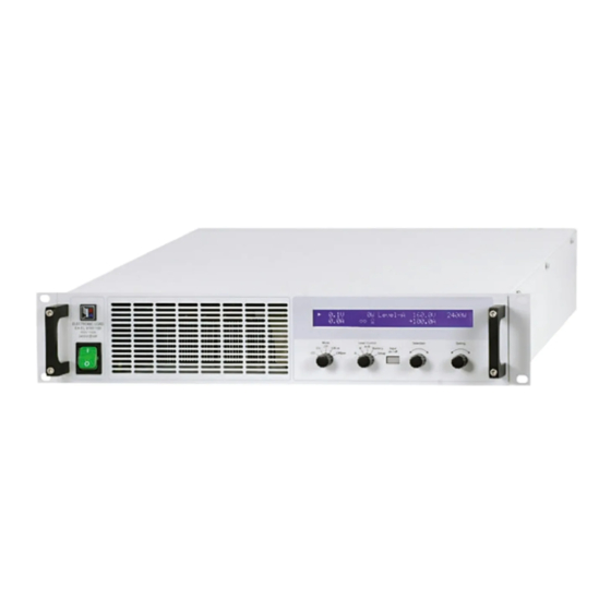
关于产品 3. 外观 3.1 前视图 图 1 3.2 后视图 图 2 EL 9000 HP 系列 日期:06-06-2011 产品说明书... -
Page 8: 供应清单
关于产品 3.3 供应清单 4.7 温度特性 1 x 电子负载 电子负载高功率版是使产品在更高环境温度下也能提供全 额输入功率。见下面对比图: 1 x 印刷版使用说明书 1 x 电源线 4. 基本信息 4.1 序言/警告 本操作说明书和产品专给对本电子负载有基本了解的人士 使用。本产品不应给无基本电器知识的人士操作,因本说 明书未作此方面解释。操作不当和未遵守安全说明的操作 可能会损坏产品或丧失产品保修权利! 4.2 与主电源的连接/接地 本产品通过电源线接地,因此只可与带接地片的电源插座 使用。 千万不可用无接地的延长线打断线路! 本系列产品随环境温度出现的功率降额,与标准版不 4.3 制冷 同: 前板和后板的通风孔必须保持干净,以保证良好的冷却 效果。注意产品(后方)要与周围摆放的任何物体保持至 少20cm距离,以便保证空气通畅。 注意!通风孔处可能有热空气流出! 4.4 拆卸 警告! 严禁用户对本产品自行拆开和修理。 打开本产品或用工具从内部拆除零件时,可能有高压触... -
Page 9: 与市电的连接
关于产品 5. 安装 5.1 目检 收到本产品后,请检查是否有外观受损痕迹。如有,请不 要操作本产品,应立即联系您的供应商。 5.2 与市电的连接 使用随附于产品的电源线与市电相连。 电源插座为IEC320型10A插座,电源线长1.5m,导体直 径为 3 x 0.75mm²。 本产品装有5x20mm保险丝(T2.5A),从后板可拆装更换。 5.3 直流输入端 负载器的输入端位于产品后面。在此处用螺丝固定与任 何馈源的连接。请随时注意设备的正确极性!仅允许连 接直流电压! 产品的输入端并无容丝装置。为避免馈源损坏负载器,应 随时注意电子负载器的标称值。如有必要,特别是在给电 池放电时,可在负载器和馈源之间加装一额外的保险丝。 负载线的直径随输入电流而定。我们建议这样使用: 100A: 2 x 10mm² 或至少1 x 35mm² 200A: 2 x 35mm²或至少1 x 95mm² 400A: 2 x 95mm²或至少1 x 240mm² 针对每根线(弹性线x 如有“+”和“-”输入脚,可将其中任一一脚接地。连接... - Page 10 操作产品 6. 操作 关于所有操作部件的综述也可参考章节3.1。 6.1 显示 下面为两行显示屏的总图和布局。左图通常显示负载输 入启动后的实际值: 图 3 调整模式指示符号(三角形)出现于实际值旁边,它与负 载器当前运行的调整模式相关。如果某标称值超标,根 据选定的不同调整模式而不同。限流或限功率要优先于 限电压或限阻值。这表示,只要标称电流被超过,负载即 转至恒流限制,三角形符号出现而指示出来。 在待机(负载输入关闭)情况下,显示Standby状态,并 只显示实际电压值: 图 7.1 Overvoltage Overtemperature 文本 或 显示错误状态。 如果负载变热,过温错误出现(见“2. 技术规格”) 图 4 。负载输入关闭并持续到错误消失为止。负载冷却后又 显示屏右半边的这部分内容指示不同的操作模式和错误 自动打开。 种类: 如果直流输入的过压极限被超越,过压错误出现。本错 误持续关闭负载输入,直到排除错误后再重新启动负载。 报警管理器 图 5 错误指示一直显示于屏幕上,直至用“Input on/off”按钮 确认为止。目的在于告知用户报警是存在还是已经消除。 当负载器通过可选接口卡设置在远程控制模式下(Remote mode)时出现这部分内容。在模式则可能为Level A, B 例如:...
-
Page 11: 操作元件
操作产品 Input on/off (4)按钮 6.2 操作元件 用于激活(连线)和关闭(断线)负载操作。 如果在电池测试模式下按下本按钮,负载设 为“断线”,计时停止。负载设为“连线”时 Power (1)主电源开关 计时继续。 用于打开或关闭负载器。 负载激活操作可因某些原因被阻止。比如:过压或其它错 误出现,或负载由模拟或数字接口(接口卡)远程控制。 也用于确认显示屏上的报警指示。按下本按钮,显示的 Mode (2)选择器 错误信息被清除(只要报警没有工作),按钮可照常使用。 用于预选负载将运行的调整模式。 在远程操作下,即由数字接口卡控制模式下,按住按钮 >3s,可将远程操作强行恢复至默认模式。 如果达到负载器的标称值并被限 定,不同调整模式会相互影响。这 能使恒功率控制(CP)模式被选定, Selection (5)旋钮 即使之前已经设置恒流控制(CC)为 本旋钮无终止点。Selection (5)的每个位置 运行模式。于是当前运行的调整模 式显示在显示屏上。更多关于各调整模式的内容请见章 对应显示屏的某一元素和设置菜单的某一参 节“6.6 预选调整模式”。 数。并在被选的元素/参数前出现箭头(->)。 有下列可选模式: 选 择 顺 序 为 : 顺 时 针 旋 转 时 , 顶-底-右-底。如果箭头指向电压设定... -
Page 12: 打开Input On/Off开关
操作产品 6.4 打开input on/off开关 6.6 预选调整模式 按下Input on/off (4)按钮,直流输入打开,产品开始以 选择器Mode (2)预先选择决定内部调整特性的调整模式。 有4种模式可选: CC, CV, CP 和 CR。 负载器工作。 再次按下按钮,输入关闭。 是指恒流。此时可调节电流和功率设定值。在此模 如果负载之前已被启动,通过模拟接口(pin = low)叫 式下输入电流被调整并限定为调节值(限流),只要馈源 „REM-SB“的引脚可关闭输入。如果负载之前已被关闭, 能输出电流。功率设定值另外限定消耗功率,影响最大 则不可再打开输入。 电流。功率限制优先于电流限制。 如果Keep set values参数被设为no,手动转换至CC调 负载工作时,电流、电压、功率和阻抗所有这4个实际值 都显示在屏幕左半边。 整模式可将功率设定值恢复至其标称值,电流设定值为 0。如果是yes,保留调整最小的设定值。详情见“7.1 设 负载输入关闭时,只显示实际电压值,因为此时无其它合 置菜单”。 理的实际值。在电池测试模式按下本按钮,计时器停止。 负载操作的激活可因某些原因而被阻止。比如:出现过 是指恒压。此时可调节电压、电流和功率设定值。 压或其它错误,或负载由模拟或数字接口远程控制(接 在此模式下,接载太多馈源会引起输出电压爆跌,输入... -
Page 13: Level A和Level B的使用
操作产品 Externer Trigger 6.7 Level A和Level B的使用 介绍 以触发输入(模拟接口)实现A与B间的外部转换只有在 Level A/B模式下才能执行。触发输入必须在菜单设置下 Level A和Level B代表两组不同的可以转换的设定值。可 mode(见“7. 产品配置”)激活。默认设置 利用Trigger 通过Level Control (3)选择器手动转换,或者通过带触发 为internal。设为external 后可通过触发输入进行A和B 输入的模拟接口从外部转换。或者自动转换(A/B模式)以 等级的转换。 便产生电压跃变。 此时调整后的升/降时间仍然有效,但是脉宽则由触发信 A和B都有对应4个调整模式的5组设定值。意思是电流设 号来决定,触发信号馈入触发输入。本信号必须为方波, 定值对应恒流模式,以A或B的值来表示。例如:在CP 等级请参考“8. 模拟接口”。 模式下,您可以调节功率的两组设定值,在他们之间进 行切换,产生功率跃变。使用A/B模式时(见6.7.3),连 只要外部触发在运行,A和B的脉冲时间就不再显示也不可 同A和B的可调脉宽(即:脉冲时间)进行自动转换。这时 调。显示器显示„Ext. trigger active“状态。 产生方波设定值,其高级别以A值来表示,低级别以B值 Selection(5) 旋钮用于选择A与B的设定值,和脉冲时间, 表示,时间段(或频率)以A和B的可变脉宽总和表示。这 而Setting(6)则来改变它们。显示屏上显示字母A和B的分... -
Page 14: 升/降时间
操作产品 图 9. 在CP调整模式下的正常负载操作 图 10. 带脉宽调节的Level A/B 操作模式 6.8 电池测试模式 介绍 电池测试模式能让用户将电池连到负载对电池定义放电。 测量平均电流,计算累计时间,然后将消耗容量以AH显 示出来。电压监控和可调欠压一起关闭Ulow极限,防止 电池过放。这个极限需调整至少一次。如果测试过程中 超过极限,负载输入自动关闭,计时器终止。电池不再 输出电流。如果极限大于电池电压,测试则不能开始。 选择调整模式 图 12 调整模式必须在转至电池测试模式前通过Mode(2)来选 择。然后您可改变电流、功率或者阻抗设定值。电池测 试不适合在恒压模式下操作,显示器也会显示这样的内 容:Battery test unsupported in CV mode(CV模式 不支持电池测试)。这仅仅告诉用户去选择其它不同的调 图12显示了设定值((U, I, P or R) 和可调脉宽和可变振幅 整模式。 的变化图。升/降时间也可调,但A和B值相等。 通过Level Control(3) 选择开关转至Battery后或者正在 如果升/降时间设至最小,脉动操作的信号接近理想方波... -
Page 15: 报警管理器
操作产品 6.11 串联和并联连接 注意:如用Mode(2)改变了调整模式,在选定模式下不可 调的所有其它设定值将被设为默认值以便测试模式正确操 多台负载可以并联,但也不是完全支持。意思是,并联时 作。因此Keep set values 在此时失效。 电流不会自动分配。故用户需注意正确控制产品。 图13举了一个(一款2400W型号的负载)达到100A的电流 并联操作时,通过控制板或接口卡(数字或模拟)对并 例子,因为限功率已经在运作。 联中所有产品的U,I,P和R调节成相同数值,从而达到平 均分配的效果。 关于时间显示的提示: 本产品的显示时间不是准确的。显示时间与实际耗时的 注意!本系列产品不可串联!否则产品会受损。 偏差为每小时1-2秒。 6.9 报警管理器 报警管理器由两部分组成:第一,最新的报警信息显示 6.12 System Bus的功能 并保留于屏幕上(见图7.2),直到被用户确认才清除;第 6.12.1 两象限操作 二,三种不同的报警信息存储在一个内部错误缓冲区内。 共享总线引脚用于设置两象限操作系统(只能应用于 因为首次出现的报警被认为是重要的,当有更多错误出现 PS9000、PSI9000、PSI8000和PS8000系列产品的结 时会被推向错误缓冲区的末尾而不是被覆盖。 合使用)。使用本操作必须将System Bus-系统总线引脚 如果缓冲区已满,只要没被数字接口卡输入的指令读取, 进行下列连线: 最后输进去的报警信息被最新的信息覆盖。读出缓冲器会 连接(EL9000的共享总线-Share Bus)第5脚到(电源的共 腾空本区域,也自动确认显示屏上的报警信息。 享总线-Share Bus)第5脚,(EL9000的AGND脚)第6脚到... -
Page 16: 横向调整 (两象限操作)
操作产品 6.12.3 横向调整 (两象限操作) 使用两象限操作,即:负载与电源一起操作,必须使用 系统总线,从而负载可控制电源。在终端系统总线的引 脚2(I-Cross) 和3(I-Cross-Rtn) 连上一电阻(0.25W),以 便向电源与负载间注入横向电流,本电流影响负载和电 源持久运行,并更快速地进行设定值的更改。下列运用: R = 0 --> 横向电流为负载标称电流的10% R = 无穷值 --> 横向电流 = 0 (默认) 通过电阻的改变可对横向电流在负载标称电流的0至10% 之间持续调节。 实际上,本操作只在少数特殊应用中使用,要求两象限 间极其快速的负载更改。公同应用如:符合DIN40839要 求的自动瞬间启动不要求这个功能。 6.12.4 远程感测 远程感测的特点在章节“5. 安装”有描述。 6.12.5 System Bus-终端系统总线各引脚分布说明 Pin 1 = Sense (+) Pin 2 = I-Cross Pin 3 = I-Cross-Rtn Pin 4 = Sense (-) Pin 5 = Share Bus... -
Page 17: 产品配置
操作产品 CAN Baud rate 7. 产品配置 可能性设置:10kBd, 20KBd, 50kBd, 100kBd, 125kBd, 7.1 设置菜单 250kBd, 500kBd, 1MBd 除非在遥控模式(通过接口卡)或外控模式(模拟接口)运行 默认设置:100kBd 中,用Level(3)选择器可随时启动设置菜单。负载在设置 过程中不可进行正常负载操作。 属于:CAN接口卡IF-C1 显示屏根据安装的接口卡显示一定数量的参数。这些参 解释:决定CAN总线的波特率(传输速度)。如果将CAN 数可由Selection(5)选定并由Selection(6)改变。显示屏 卡连到现有网络,您必须设置与总线正在使用的相同的 右边的两个三角形指示出还有更多参数。显示屏第一行 波特率,因为总线上的任何负载必须使用相同总线速度。 进一步显示安装卡的型号,如:IF-U1 CAN Relocatable ID 可能性设置:0...31 图 14 默认设置:0 第二行接着显示由Selection(5)选择的所有参数。这些 属于:CAN接口卡IF-C1 参数根据配备的接口卡会不同。下面列出可能出现的参 数极其设置: 解释:本设置决定CAN产品节点所处的(可再定位)地址 段。要了解更多信息请参考基本的CAN技术规格。举... -
Page 18: 模拟接口
操作产品 VREF输出端用于生成VSEL,CSEL,PSEL和RSEL设定 8. 模拟接口 • 值。举例:如果只需要CC调整模式,VSEL设定输入 介绍 必须固定为0V,通过0-10V外部源或可调电位器(GND 模拟接口为一个位于产品后面板的带15个引脚的Sub-D插 和VREF,滑动开关至CSEL)给PSEL,VREF和CSEL 座,专用于通过外部硬件 (如:开关电源, 开关,继电器) 供电。见下表。 遥控电子负载的最重要功能。 Level A/B模式下可调升/降时间和脉宽此时失效。如 • 负载必须转至外部控制以便使用模拟接口。需要连一跳 果期望得到某种形式的振幅-时间-进度,通过一外部 线(或开关)在第7引脚(远程)和第6引脚(接地)之间。 函数发生器产生和输入。 于是显示屏显示状态如下: mode)下触发输入无 在模拟接口控制模式(External • 功能。即只能由输入设定值输入端的信号产生设定值 跃变。 8.2 配置举例 图 15 下表列举了多个单一或组合调整模式的设置。如果不使 避免将负载在远程或电池测试模式下转换到外部操作模 用阻抗调整模式,必须将第7引脚 (远程)和第12引脚 ( 式! 远程)的电压拉到0V。 在任何状态(除菜单设置运行外)下都能转换到外部控 解释:不需对任何固定输入端提供10V的固定电压。可以... -
Page 19: 应用举例
操作产品 8.3 应用举例 输入关闭 各引脚概况 图18显示了模拟接口执行远程关闭输出的连线图。本功能 可随时使用,不需用Remote引脚启动外控。可通过各种 AGnd RSEL 不同接触件,如三极管,继电器,开关等实现与其它应用 DGnd PSEL 设备的结合操作。 Remote CSEL Rem-SB VSEL OVP/OT Trigger In VMON R-Range CMON REMOTE R-active VRef REM-SB DGND 图 16 图 18 模拟主-辅机操作 外控模式的转换 真正的主辅机操作是不可能实现的,因为模拟接口不提供 设定值输出。但是在有些情况下主机的监控输出CMON甚 外控模式的转换在产品即将由外部模拟信号控制时才需 至VMON都可用来控制一台或多台辅助负载器的四组设定 求。如果使用模拟主辅机操作,则只要将辅机转换至外 值输入中的一组。 控模式即可。转换通过极端器或开关来实现。... -
Page 20: 模拟接口各引脚分布说明
操作产品 只外控电流 如上述例子一样,但只有电流可调。功率设为最大值。 DGND VREF CSEL AGND 图 21 8.4 模拟接口各引脚分布说明 引脚 名称 类型² 描述 电位 电气规格 VSEL 电压设定值 0…10V,对应0..100%的U 精确度典型值为 0,1% CSEL 电流设定值 0…10V,对应0..100%的I 输入阻抗 Ri > 40k…100K PSEL 功率设定值 0…10V,对应0..100%的P RSEL 阻抗设定值 0…10V,对应0..100%的R AGND POT 模拟信号参考电位 针对VSEL, CSEL, PSEL, RSEL, VMON, CMON, PMON, VREF DGND POT 数字信号参考电位... -
Page 21: 接口卡
操作产品 9. 接口卡 应用举例 下列这些图片显示通过电脑控制一台或多台负载器的多种 应用的几种。这同样应用于与电源混合配置。 基本信息 图 23的 设 置 也 可 限 制 性 地 用 于 RS232和 IF-R1接 口 本电子负载支持各种接口卡。所有都电绝缘至2000V。 卡。LabView VIs 软件通过RS232目前只支持一台负载。 IF-R1(RS232), IF-C1(CAN) 和IF-U1(USB) 数字卡支持统 一通讯协议。IEE/GPIB卡IF-G1根据SCPI标准使用文本协 议。所有这些卡通过电脑来监控和控制1到30台负载器, 但是使用IEEE就只能控制到16台仪器。 而IF-E1网卡一方面可提供像IEEE卡一样的基于SCPI协 议的文本。另一方面,该卡还有另外一个USB端口,可 使用上述双重通讯协议。 不同卡的设置 接口卡要求不同的至少设置一次的设置参数。详情见章 节“7. 产品配置”。 关于接口卡的更多信息和技术规格可参考其用户指导说... -
Page 22: 其它附件和选项功能
操作产品 10. 附件 10.1 其它附件和选项功能 注意:关于选项功能和附件详情请见各个产品操作说明 书。 可供下列附件: a) USB-至-模拟接口UTA12 经USB(电脑面)和产品内置模拟接口远程控制。 b) 数字接口卡 还配USB,RS232,CAN,GPIB/IEEE (仅SCPI) 或以太 网/LAN (SCPI )用可插拔式数字接口卡。 还供下列选项: a) 水冷式结构 可内置水冷设备。不再需要额外的风扇,但在过温时关 断功率阶段的输出。水冷式结构旨在获取更高连续输入 功率的同时,减少负载的随温功率降额,亦或避免随温 降额的出现。 EL 9000 HP 系列 日期:06-06-2011 产品说明书... - Page 25 General About Safety instructions Elektro-Automatik GmbH & Co. KG Only operate the device at a mains voltage as stipulated • on the type plate Never insert mechanical parts, especially from metal, • through the air ventilation slots Avoid any use of liquids of any kind in the proximity of •...
- Page 26 Table of content Page Introduction................................ 27 Technical specifications ............................. 27 Control panel ..............................27 Device specific data ............................. 28 Design ................................29 Front view ..............................29 Rear view ..............................29 Scope of delivery ............................30 General................................30 Prologue / Warning ............................30 Mains connection / Grounding ........................
-
Page 27: Introduction
About the device Introduction Technical specifications Control panel The electronic loads of the series EL9000 HP are very efficient devices which offer a big variety of interesting Type features in a 19“ case at only 4U. Besides the common functionality of electronic loads you can test batteries, Display: two line character LCD with load voltage or current sources with a pulsed operation,... -
Page 28: Device Specific Data
About the device Device specific data EL9080-400 HP EL 9160-200 HP EL9400-100 HP EL9750-50 HP Mains input Mains voltage 115V/230V selectable Mains frequency 50/60Hz Mains fuse T2,5A DC input Input voltage U 160V 400V 750V Input power P 4800W, with temperature related derating - permanent power 4800W at 40°C ambient temp. -
Page 29: Design
About the device Design Front view Figure 1 Rear view Figure 2 Instruction Manual Date: 06-06-2011 EL 9000 HP Series... -
Page 30: Scope Of Delivery
About the device Scope of delivery Dynamic characteristics and stability criteria 1 x Electronic load The electronic load is characterised by short rise and fall times of the current, which are achieved by a high 1 x Printed instruction manual bandwidth of the internal regulation circuit. -
Page 31: Relation Between Input Voltage And Input Current
About the device Relation of input voltage to input current One of the inputs “+” and “-“ can be grounded if required. When working with applications that input only low Doing so you must observe following: voltages to the load, it becomes necessary to know the The „-“... -
Page 32: Handling
Handling the device Handling For an overview of all operating elements also see 3.1. The display This is an overview of the two line display and its layout. The left side always shows actual values while the load input is switched on: Figure 3 The indicator for the regulation mode(a triangle) appears next to the actual value, which is related to currently... -
Page 33: Operating Elements
Handling the device Operating elements Explanation of the selector positions: Switches to the set values of Level A. These values become instantly active and can be changed now. Mains switch Power (1) Switches to the set values of Level B. These Is used to switch the device on or off. -
Page 34: Switching Power On
Handling the device Adjusting the set values Rotary knob Setting (6) Note: Set values, which must not be changed in the cur- This rotary knob has no end stop. With every rently selected regulation mode, are not shown and can position Setting (6) changes the set value not be selected/changed. -
Page 35: Usage Of Level A And Level B
Handling the device The manual changeover to regulation mode CV can reset The manual changeover to regulation mode CR can reset the set values of voltage, power and current to their no- the set values of resistance, current and power to their minal values, if the parameter Keep set values has been... -
Page 36: Level B
Handling the device 6.7.2 Level B External trigger When selecting Level B with the selector Level Con- The external switchover between A and B, realised with trol(3) the load is switched to manual operation. This the trigger input (analogue interface), is only available mode works the same way as Level A, with the difference in Level A/B mode. -
Page 37: Rise/Fall Time
Handling the device Note: during Level A/B operation following applies: the Note: the pulse widths of A and B should always be gre- set value of A must always be greater than or equal to ater than the rise/fall time, else the pulsed signal would B. -
Page 38: Alarm Management
Handling the device 6.10 Control locations and priorities Note: if external control by analogue interface is activated (pin REMOTE = low) while the battery test is running, the Control locations are the locations from where the device test is aborted. After external control has left again and if is controlled. -
Page 39: Functions Of The Terminal System Bus
Handling the device 6.12 Functions of the terminal System Bus 6.12.4 Remote sense The remote sense feature is described in section “5. 6.12.1 Two-quadrants operation Installation”. The Share Bus pin (only usable in combination with the power supplies PS9000 and PSI9000) can be used to 6.12.5 Pin assignment of terminal System Bus set up a system for two-quadrants operation. -
Page 40: Device Configuration
Handling the Gerätes Device configuration CAN Baud rate Possible settings: 10kBd, 20KBd, 50kBd, 100kBd, The setup menu 125kBd, 250kBd, 500kBd, 1MBd The setup menu can activated anytime by the selector Default setting: 100kBd Level(3), except during remote control mode (by interface Belongs to: CAN interface card IF-C1 card) or external mode (analogue interface). -
Page 41: The Analogue Interface
Handling the device The analogue interface if resistance regulation is used, you can select the • resistance range before or while using the analogue Introduction interface. Pin 13 (R-Range) is used to switch between The analogue interface is a 15pole Sub-D socket and is the two ranges: located at the rear side. -
Page 42: Example Applications
Handling the device Example applications Overview of the pins AGnd RSEL DGnd PSEL Remote CSEL Rem-SB VSEL REMOTE REM-SB DGND Figure 18 Figure 16 OVP/OT Trigger In VMON Switching to external control R-Range CMON Switching to external control is only required if the device R-active VRef is going to be controlled by external analogue signals. -
Page 43: Pin Assignment Of The Analogue Interface
Handling the device External control with current only Like in the example above, but only current adjustable. The power is set to maximum. DGND VREF CSEL AGND Figure 21 Pin assignment of the analogue inter- Name Type² Description Level Electrical specifications VSEL Set value for voltage 0…10V, corresponds to 0..100% of U... -
Page 44: Interface Cards
Handling the device Interface cards Application examples The following figures show only some of many possible applications when controlling one or multiple electronic General loads by a PC. The same applies for mixed configurations The electronic load supports various interface cards. All with power supplies. -
Page 45: Miscellaneous
Handling the device 10. Miscellaneous 10.1 Accessories and options Note: Details about options and accessories are avaible in seperate instruction manuals. Following accessories are optionally available: a) USB-to-Analogue interface UTA12 Galvanically isolated remote control via USB (on PC side) and the device internal analogue interface. b) Digital interface cards RS232, CAN, GPIB/IEEE (SCPI only) or Ethernet/LAN (SCPI) are available. - Page 46 地址:苏州吴中区珠江南路378号431室 邮箱:amaygang@163.com 网址:www.d-wellmeter.com 传真:0512-66315383 电话:0512-66315386 手机:13913158248 免费服务热线:400-902-3318...
- Page 47 地址:苏州吴中区珠江南路378号431室 邮箱:amaygang@163.com 网址:www.d-wellmeter.com 传真:0512-66315383 电话:0512-66315386 手机:13913158248 免费服务热线:400-902-3318...
- Page 48 EA-Elektro-Automatik GmbH & Co. KG 研发 - 生产 - 销售一体化 Helmholtzstraße 31-33 41747 Viersen Germany Tel: +49 2162 / 37 850 Fax: +49 2162 / 16 230 ea1974@elektroautomatik.cn www.elektroautomatik.cn...
Need help?
Do you have a question about the EL 9080-400 HP and is the answer not in the manual?
Questions and answers