Elektro-Automatik EL 9000 HP Series Instruction Manual
Hide thumbs
Also See for EL 9000 HP Series:
- Operating manual (43 pages) ,
- Operating manual (46 pages) ,
- Instruction manual (46 pages)

Subscribe to Our Youtube Channel
Related Manuals for Elektro-Automatik EL 9000 HP Series


Summary of Contents for Elektro-Automatik EL 9000 HP Series
- Page 1 电子负载系列 Electronic Load Series EL 9000 HP 80V/160V/400V/750V 75A/150A/300A/600A 7200W EL 9080-600 HP: 33 200 246 EL 9160-300 HP: 33 200 247 EL 9400-150 HP: 33 200 248 EL 9750-75 HP: 33 200 251...
- Page 3 概述 © Elektro-Automatik 安全须知 严禁再版、复印或部分错误地使用本说明书,否则将承 担本行为导致的法律后果。 请仅在铭板标示电压下操作本仪器。 • 请勿将任何机械零件,特别是金属件,插入仪器内,否 • 则将有触电危险或损坏仪器。 请避免在仪器周围使用任何液体物质,因有可能进入仪 • 器内部并损坏它。 请勿将高于负载额定电压的电压源连接到负载上。比如 • 80V型号的负载,不能连接高于100V的电压源,160V 型号不能连接高于180V的电压源,400V的产品不能连 接460V电压源。 从后板插槽上安装接口卡时,请遵循一般防静电规则。 • 接口卡只能在仪器完全关闭(电源开关关闭)后插入和 • 取出。 当连接其它电压源或电池,或者使用模拟接口时,总是 • 先查看应用设备的各项限定值和标称值。 DC输入端无保险丝熔断保护! • EL 9000 HP 系列 日期:05-31-2011 产品说明书...
-
Page 4: Table Of Contents
索引 页码 介绍 ..................................5 技术规格 ................................5 控制面板 ................................. 5 各产品型号详细规格 ............................6 外观 ..................................7 前视图 ................................7 后视图 ................................8 供应清单 ................................. 9 基本信息 ................................9 序言/警告 ............................... 9 与主电源的连接/接地 ............................. 9 制冷 ................................9 拆卸 ................................9 温控关断/通风... -
Page 5: 技术规格
关于产品 介绍 技术规格 控制面板 EL9000 HP系列电子负载为极其高效之产品,建造于仅 9U式的19“外壳内,给用户提供多种有趣的特性。除电 型号 子负载的一般功能外,本产品可以在脉动模式下测试电 80个字符,两行显示的LCD 池、加载电压或电流源,其脉冲宽度和幅度皆可调。您 显示器: 也可通过接口卡遥控本产品,通过电脑几乎能控制和监 2个旋钮,2 个旋转开关, 运行元素: 控其所有功能。 1个按钮 通过其中一接口卡,能轻易融入现有系统,并且非常直观 显示格式 地完成产品配置。故本电子负载可与PS9000/PSI9000系 标称值决定可调范围。 列电源结合一起操作,或经由产品后面的模拟接口插座, 通过模拟接口由其它设备来控制和监控。 只要当前运行操作模式允许,可一次性显示实际值和设 定值。 本产品由微处理器控制,得以使产品能准确、快速地测量 和显示出各实际值,并具备一般标准模拟技术不能实现的 多项新扩展可操作性功能。 电压值显示 现代化的设计赋予产品最高性能的同时,也实现了在节 4位数 分辨率: 省的空间内进行复杂和有效应用的理念,比如:为符合 0.0V…999.0V 格式: 研究和开发领域不同需求或演示和测试目的,具有可变 功率的工业测试仪器。 电流值显示 可拔插式数控接口卡大大简化了与象CAN一样的专业工 4位数... -
Page 6: 各产品型号详细规格
关于产品 各产品型号详细规格 EL9080-600 HP EL 9160-300 HP EL9400-150 HP EL9750-75 HP 主电源输入 输入电压 115V/230V 可转换 输入频率 50/60Hz 输入保险 T2,5A 直流输出 输入电压 U 160V 400V 750V 输入功率 P 7200W,随温度降额 - 固定功率 在40°C环境温度时为7200W 输入电流 I 600A 300A 150A 过压保护极限 1.1 * U 最大允许输入电压... -
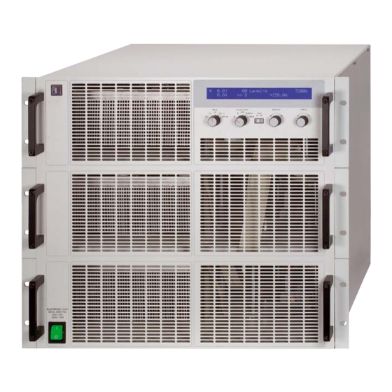
Page 7: 前视图
关于产品 外观 前视图 图 1 EL 9000 HP 系列 日期:05-31-2011 产品说明书... -
Page 8: 后视图
关于产品 后视图 图 2 EL 9000 HP 系列 日期:05-31-2011 产品说明书... -
Page 9: 供应清单
关于产品 供应清单 温度特性 1 x 电子负载 高功率电子负载为改良版,故在更高环境温度下,功率降 额钱,也能提供全额输入功率。见下面对比图: 1 x 印刷版使用说明书 1 x 电源线 基本信息 序言/警告 本操作说明书和产品专给对本电子负载有基本了解的人士 使用。本产品不应给无基本电器知识的人士操作,因本说 明书未作此方面解释。操作不当和未遵守安全说明的操作 可能会损坏产品或丧失产品保修权利! 与主电源的连接/接地 本产品通过电源线接地,因此只可与带接地片的电源插座 使用。 千万不可用无接地的延长线打断线路! 如果出现功率降额,它将随环境温度而变化: 制冷 前板和后板的通风孔必须保持干净,以保证良好的冷却 效果。注意产品(后方)要与周围摆放的任何物体保持至 少20cm距离,以便保证空气通畅。 注意!通风孔处可能有热空气流出! 拆卸 警告! 严禁用户对本产品自行拆开和修理。 打开本产品或用工具从内部拆除零件时,可能有高压触 电的危险。必须将本产品与主电源断开后方才进行,否 则用户自行承担风险。 只有受过电流危险知识训练的人员才可进行相关的维护 或修理。 温控关断/通风 输入电压和输入电流间的关系 本产品装有长期运转的温控风扇。遇高温时,RPM增加,... -
Page 10: 与市电的连接
关于产品 远程感测的使用和连接 EL9400-150 zu U to U 远程感测线连到System Bus上,更多信息请见章节„6.12 System Bus的功能“。 为补偿馈源和负载器间负载线(每根线最大1.1V)的压降, 负载器可测量System Bus远程感测端馈源的电压,然后 进行相应调整。按正确极性连接到产品后面的System Bus端子的引脚1(+感测端)和引脚4(–感测端)。建议使用 – 2,5mm 直径为0,2mm ,带线端护套的弹性线。 (+) 感测端只能与馈源(+)输出端相连,(–)感测端与输 安装 出(–)端相连,否则可能会损坏本产品。 目检 收到本产品后,请检查是否有外观受损痕迹。如有,请不 接口卡插槽 要操作本产品,应立即联系您的供应商。 本产品可配接口卡。接口卡插槽位于产品后面。关于接口 卡更多信息见章节9。 与市电的连接 使用随附于产品的电源线与市电相连。 电源插座为IEC320型10A插座,电源线长1.5m,导体直 径为 3 x 0.75mm²。 本产品装有5x20mm的保险丝(T2.5A),从后面板可拆装 更换。 直流输入端 负载器的输入端位于产品后面。在此处用螺丝固定与任... - Page 11 操作产品 操作 关于所有操作不见的综述也可参考章节3.1。 显示 下面为两行显示屏的总图和布局。左图通常显示负载输 入启动后的实际值: 图 3 调整模式指示符号(三角形)出现于实际值旁边,它与负 载器当前运行的调整模式相关。如果某标称值超标,根 据选定的不同调整模式而不同。限流或限功率要优先于 限电压或限阻值。这表示,只要标称电流被超过,负载即 转至恒流限制,三角形符号出现而指示出来。 在待机(负载输入关闭)情况下,显示Standby状态,并 只显示实际电压值: 图 7.1 Overvoltage Overtemperature 文本 或 显示错误状态。 如果负载变热,过温错误出现。负载输入关闭并持续到 错误消失为止。负载冷却后又自动打开。 图 4 如果直流输入的过压极限被超越(见„2. 技术规格“), 显示屏右半边的这部分内容指示不同的操作模式和错误 过压错误出现。本错误持续关闭负载输入,直到排除错误 种类: 后再重新启动负载。 报警管理器 错误指示一直显示于屏幕上,直至用“Input on/off”按钮 图 5 确认为止。目的在于告知用户报警是存在还是已经消除。 例如: 当负载器通过可选接口卡设置在远程控制模式下(Remote mode)时出现这部分内容。在模式则可能为Level A, B 和...
-
Page 12: 操作按钮
操作产品 Input on/off (4)按钮 操作按钮 用于激活(连线)和关闭(断线)负载操作。 Power (1)主电源开关 如果在电池测试模式下按下本按钮,负载设 为“断线”,计时停止。负载设为“连线”时 用于打开或关闭负载器。 计时继续。 负载激活操作可因某些原因被阻止。比如:过压或其它错 误出现,或负载由模拟或数字接口(接口卡)远程控制。 Mode (2)选择器 也用于确认显示屏上的报警指示。按下本按钮,显示的 用于预选负载将运行的调整模式。 错误信息被清除(只要报警没有工作),按钮可照常使用。 如果达到负载器的标称值并被限 在远程操作下,即由数字接口卡控制模式下,按住按钮 定,不同调整模式会相互影响。这 >3s,可将远程操作强行恢复至默认模式。 能使恒功率控制(CP)模式被选定, 即使之前已经设置恒流控制(CC)为 Selection (5)旋钮 运行模式。于是当前运行的调整模 式显示在显示屏上。更多关于各调 本旋钮无终止点。Selection (5)的每个位置 整模式的内容请见章节„6.6 预选调整模式“。 对应显示屏的某一元素和设置菜单的某一参 有下列可选模式: 数。并在被选的元素/参数前出现箭头(->)。 恒流调整 选择顺序:顺时针旋转时,顶-底-右-底。 如果箭头指向电压设定值,则移向电流设定 恒压调整 值,然后是功率设定值等,这是针对顺时针... -
Page 13: 打开Input On/Off开关
操作产品 打开input on/off开关 是指恒压。此时可调节电压、电流和功率设定值。 按下Input on/off (4)按钮,直流输入打开,产品开始以 在此模式下,接载太多馈源会引起输出电压爆跌,输入 电压会被调整并限定为调节值,如果馈源能输出大于负 负载器工作。 载能吸收的电流,则不能达到电压极限。 再次按下按钮,输入关闭。 如果Keep set values参数被设为no,手动转换至CV模 如果负载之前已被启动,通过模拟接口(pin = low)叫 式可将电压、电流和功率设定值恢复至标称值。如果是 „REM-SB“的引脚可关闭输入。如果负载之前已被关闭, yes,保留调整最小的设定值。详情见„7.1 设置菜单“。 则不可再打开输入。 注意:CV调整不能与电池测试模式一起使用。如果选了 负载工作时,电流、电压、功率和阻抗所有这4个实际值 电池测试,显示屏会出现错误信息。 都显示在屏幕左半边。 注意:指定给CV调整模式的电压设定值在除CV模式外的 负载输入关闭时,只显示实际电压值,因为此时无其它合 任何其它模式都要设置为0.因此在CC, CP或CR模式手动 理的实际值。在电池测试模式按下本按钮,计时器停止。 操作过程中访问不到。 负载操作的激活可因某些原因而被阻止。比如:出现过 远程控制模式下,可将电压设定值传输给负载,但是会被 压或其它错误,或负载由模拟或数字接口远程控制(接 忽略,并由通讯工具报告访问错误。 口卡)。 外部控制(模拟接口)模式下有个例外:需先给出电压设 待机状态(输入=关闭)显示如下: 定值,然后才能按期望使用,如果要求正常的CC, CP或 CR操作,应将电压值设为0V。... -
Page 14: Level A和Level B的使用
操作产品 Externer Trigger Level A和Level B的使用 介绍 以触发输入(模拟接口)实现A与B间的外部转换只有在 Level A/B模式下才能执行。触发输入必须在菜单设置下 Level A和Level B代表两组不同的可以转换的设定值。可 mode(见„7. 产品配置“)激活。默认设置为 利用Trigger 通过Level Control (3)选择器手动转换,或者通过带触发 internal。设为external 后可通过触发输入进行A和B等 输入的模拟接口从外部转换。或者自动转换(A/B模式)以 级的转换。 便产生电压跃变。 此时调整后的升/降时间仍然有效,但是脉宽则由触发信 A和B都有对应4个调整模式的5组设定值。意思是电流设 号来决定,触发信号馈入触发输入。本信号必须为方波, 定值对应恒流模式,以A或B的值来表示。例如:在CP 等级请参考„8. 模拟接口“。 模式下,您可以调节功率的两组设定值,在他们之间进 行切换,产生功率跃变。使用A/B模式时(见6.7.3),连 只要外部触发在运行,A和B的脉冲时间就不再显示也不 同A和B的可调脉宽(即:脉冲时间)进行自动转换。这时 可调。显示器显示„Ext. trigger active“状态。 产生方波设定值,其高级别以A值来表示,低级别以B值 Selection(5) 旋钮用于选择A与B的设定值,和脉冲时间, 表示,时间段(或频率)以A和B的可变脉宽总和表示。这... -
Page 15: 6.7.4 升/降时间
操作产品 图 9. 在CP调整模式下的正常负载操作 图 10. 带脉宽调节的Level A/B 操作模式 电池测试模式 介绍 电池测试模式能让用户将电池连到负载对电池定义放电。 测量平均电流,计算累计时间,然后将消耗容量以AH显 示出来。电压监控和可调欠压一起关闭Ulow极限,防止 电池过放。这个极限需调整至少一次。如果测试过程中 超过极限,负载输入自动关闭,计时器终止。电池不再 输出电流。如果极限大于电池电压,测试则不能开始。 选择调整模式 可在任何时候更改调整模式,即使正在运行测试也可以。 图 12 该操作可重设整个测试,包括计时器和Ah值。 使用 测试之前和测试过程中都可进行调整模式设定值的调节, 欠压会关闭Ulow极限。用Selection(5)选定设定值。用 图12显示了设定值((U, I, P or R) 和可调脉宽和可变振幅 Setting(6)调节。显示器以小时:分:秒(HH:MM:SS)的 的变化图。升/降时间也可调,但A和B值相等。 格式显示累计时间,以Ah为单位显示消耗容量。 如果升/降时间设至最小,脉动操作的信号接近理想方波 计算Ah值 形状。图12只是一个阐述图。举一个实际变化的例子: 安培小时值(吸取的电荷)是最后两次测得的输入电流的平 由1KHZ频率脉动形成的输入电流会多少有些不同。这 均值乘以所用时间而计算出来的。 取决于很多条件,比如馈电源的调整时间,负载的调整 时间,连接线的阻抗等。... -
Page 16: 报警管理器
操作产品 报警管理器 6.11 串联和并联连接 报警管理器由两部分组成:第一,最新的报警信息显示 多台负载可以并联,但也不是完全支持。意思是,并联时 并保留于屏幕上(见图7.2),直到被用户确认才清除;第 电流不会自动分配。故用户需注意正确控制产品。 二,三种不同的报警信息存储在一个内部错误缓冲区内。 并联操作时,通过控制板或接口卡(数字或模拟)对并 因为首次出现的报警被认为是重要的,当有更多错误出现 联中所有产品的U,I,P和R调节成相同数值,从而达到平 时会被推向错误缓冲区的末尾而不是被覆盖。 均分配的效果。 如果缓冲区已满,只要没被数字接口卡输入的指令读取, 最后输进去的报警信息被最新的信息覆盖。读出缓冲器会 注意!本系列产品不可串联!否则产品会受损。 腾空本区域,也自动确认显示屏上的报警信息。 错误缓冲器存储三种可能输入的错误代码和状态代码,告 诉用户错误仍然运行还是已经消除。关于更多信息请参考 接口卡的使用说明。 显示器也显示指示错误的状态。目的在于告诉用户在他不 在的这个时间段出现了一个或多个报警信息,特别是只持 续很短时间的报警信息,如尖峰电压产生的过压。用户要 么按下Input on/off(4) 按钮确认他已发现这个报警指示, 要么通过通讯工具读取错误缓冲器。 注意:在遥控或外控模式下出现的报警不显示于屏幕, 因为已显示了控制模式的状态。因此只需在离开这些模 式时确认一下或者当错误被指令读取后不用做任何动作。 6.10 终端控制区域和优先顺序 控制区域是指产品被控制的区域。这有可能在产品本身( 手工控制),可能通过模拟接口(外部控制)或通过接口卡 (遥控)。为防止用户一次性从两个区域访问负载器而设 置了优先顺序。适用如下: 模拟接口具有最高优先权,数字接口第二,手动控制最 低。意思是如果产品被设为遥控,则不可用开关和旋钮 设置模式和设定值。如果在遥控运行同时转换到外控,遥 控状态将被重设,负载只能通过模拟输入控制。为了将此... -
Page 17: System Bus的功能
操作产品 6.12 System Bus的功能 6.12.1 两象限操作 共享总线引脚用于设置两象限操作系统(只能应用于 PS9000、PSI9000、PSI8000和PS8000系列产品的结 合使用)。使用本操作必须将System Bus-系统总线引脚 进行下列连线: 连接(EL9000的共享总线-Share Bus)第5脚到(电源的共 享总线-Share Bus)第5脚,(EL9000的AGND脚)第6脚到 (电源的AGND脚)第6脚。 共享总线操作过程中,电子负载当引导设备,电源当依 托设备。 两象限操作的典型应用: 能进行自动充放电循环的电池测试 • 带模拟三极管的汽车电子测试,如在引擎发动时的电 • 压中断 电容周期性充放电 • 6.12.2 选择调整速度 负载的调整速度(或时间)事先故意设为慢速,典型值为 50ms (只针对CV和CP模式)。通过此设置可稳定地载荷 像具未知调整特性的电源一样的关键馈源,并在无隔离 条件下运行。在给出最小调整时间内进入动态。见„2.2 各产品型号详细规格“章节“动态值”。 如需要更好的调整动态,可将负载转至快速调整。这需在 终端System Bus-系统总线的第7引脚(FastReg)和第6引 脚(AGnd)上完成。如果这些引脚被短路,快速调整启动。 默认状态时为慢速调整。 只有在负载完全与主电源断开后 才可改变此设置!... -
Page 18: 产品配置
操作产品 CAN Baud rate 产品配置 可能性设置:10kBd, 20KBd, 50kBd, 100kBd, 125kBd, 设置菜单 250kBd, 500kBd, 1MBd 除非在遥控模式(通过接口卡)或外控模式(模拟接口)运行 默认设置:100kBd 中,用Level(3)选择器可随时启动设置菜单。负载在设置 过程中不可进行正常负载操作。 属于:CAN接口卡IF-C1 显示屏根据安装的接口卡显示一定数量的参数。这些参 解释:决定CAN总线的波特率(传输速度)。如果将CAN 数可由Selection(5)选定并由Selection(6)改变。显示屏 卡连到现有网络,您必须设置与总线正在使用的相同的 右边的两个三角形指示出还有更多参数。显示屏第一行 波特率,因为总线上的任何负载必须使用相同总线速度。 进一步显示安装卡的型号,如:IF-U1 CAN Relocatable ID 可能性设置:0...31 图 14 默认设置:0 第二行接着显示由Selection(5)选择的所有参数。这些 属于:CAN接口卡IF-C1 参数根据配备的接口卡会不同。下面列出可能出现的参 数极其设置: 解释:本设置决定CAN产品节点所处的(可再定位)地址 段。要了解更多信息请参考基本的CAN技术规格。举 例:电子负载由于某些原因指定为地址5,这可能与另 Trigger mode 一有相同地址的总线相抵触,您可以将这个地址通过定... -
Page 19: 模拟接口
操作产品 VREF输出端用于生成VSEL,CSEL,PSEL和RSEL设定 模拟接口 • 值。举例:如果只需要CC调整模式,VSEL设定输入 介绍 必须固定为0V,通过0-10V外部源或可调电位器(GND 模拟接口为一个位于产品后面板的带15个引脚的Sub-D插 和VREF,滑动开关至CSEL)给PSEL,VREF和CSEL 座,专用于通过外部硬件 (如:开关电源, 开关,继电器) 供电。见下表。 遥控电子负载的最重要功能。 Level A/B模式下可调升/降时间和脉宽此时失效。如 • 负载必须转至外部控制以便使用模拟接口。需要连一跳 果期望得到某种形式的振幅-时间-进度,通过一外部 线(或开关)在第7引脚(远程)和第6引脚(接地)之间。 函数发生器产生和输入。 于是显示屏显示状态如下: mode)下触发输入无 在模拟接口控制模式(External • 功能。即只能由输入设定值输入端的信号产生设定值 跃变。 图 15 配置举例 可在任何状态下转至外部操作模式。最终运行的远程控制 下表列举了多个单一或组合调整模式的设置。它适用: 或电池测试被终止,于是控制区域设为“本地”。 如果不使用阻抗调整模式,必须将第7引脚 (远程)和第 优先顺序 12引脚 (远程)的电压拉到0V。 模拟接口比其它任何操作模式都有优先权。此时设定值输 解释:不需对任何固定输入端提供10V的固定电压。可以 入被启动,只有通过外部电源(PLC, 0...10V应用)或可调... -
Page 20: 应用举例
操作产品 应用举例 输入关闭 各引脚概况 图18显示了模拟接口远程关闭输出的模拟接口连线图。此 功能可随时使用,不需用Remote引脚启动外控。可通过 AGnd RSEL 各种不同接触件,如三极管,继电器,开关等实现与其它 DGnd PSEL 应用设备的结合操作。再次断开触点,如果输出在关闭( Remote CSEL 远程控制)前是开的,此时可再次打开输出,或者允许从 Rem-SB VSEL 前板手动打开输出。 OVP/OT Trigger In VMON R-Range CMON REMOTE REM-SB DGND R-active VRef 图 16 图 18 模拟主-辅机操作 外控模式的转换 真正的主辅机操作是不可能实现的,因为模拟接口不提供 外控模式的转换在产品即将由外部模拟信号控制时才需 设定值输出。但是在有些情况下主机的监控输出CMON甚 求。如果使用模拟主辅机操作,则只要将辅机转换至外 至VMON都可用来控制一台或多台辅助负载器的四组设定 控模式即可。转换通过极端器或开关来实现。... -
Page 21: 模拟接口各引脚分布说明
操作产品 只外控电流 如上述例子一样,但只有电流可调。功率设为最大值。 DGND VREF CSEL AGND 图 21 模拟接口各引脚分布说明 引脚 名称 类型² 描述 电位 电气规格 1 VSEL 电压设定值 0…10V,对应0..100%的U 精确度典型值为 0,1% 2 CSEL 电流设定值 0…10V,对应0..100%的I 输入阻抗 Ri > 40k…100K 3 PSEL 功率设定值 0…10V,对应0..100%的P 4 RSEL 阻抗设定值 0…10V,对应0..100%的R 5 AGND 模拟信号参考电位... -
Page 22: 接口卡
操作产品 接口卡 基本信息 本电子负载支持各种接口卡。所有都电绝缘至2000V。 IF-R1(RS232), IF-C1(CAN) 和IF-U1(USB) 数字卡支持统 一通讯协议。IEE/GPIB卡IF-G1根据SCPI标准使用文本协 议。所有这些卡通过电脑来监控和控制1到30台负载器, 但是使用IEEE就只能控制到16台仪器。 而IF-E1网卡一方面可提供像IEEE卡一样的基于SCPI协 议的文本。另一方面,该卡还有另外一个USB端口,可 使用上述双重通讯协议。 不同卡的设置 接口卡要求不同的至少设置一次的设置参数。详情见章 节„7. 产品配置“。 关于接口卡的更多信息和技术规格可参考其用户指导说 明。 图 22 特点 通过其中一接口卡和所供LabView VIs软件控制电子负载 器要遵循产品操作条件和各标称值。应检查设定值的合理 性,如有必要应更正或者强行改为标称值。 LabView 我们提供现成的LabView VIs接口卡软件。它不支持电子 负载的所有功能,但在不断开发和增强其功能。 在其它环境下的编程 数字通讯接口在除LabView外的其它IDEs也能普遍应用。 这个通讯协议不遵从任何标准,只代表通讯的最低级别。 在此等别下错误设置和错误设定值的安全级别较低,有可 能导致产品的误动作。请严格按照准则强制性地执行。 图 23 关于通讯协议的详细信息可参考接口卡用户指导说明。 应用举例 下列这些图片显示通过电脑控制一台或多台负载器的多种... -
Page 23: 其它附件和选项功能
操作产品 10. 附件 10.1 其它附件和选项功能 注意:关于选项功能和附件详情请见各个产品操作说明 书。 可供下列附件: a) USB-至-模拟接口UTA12 经USB(电脑面)和产品内置模拟接口远程控制。 b) 数字接口卡 还配USB,RS232,CAN,GPIB/IEEE (仅SCPI) 或以太 网/LAN (SCPI )用可插拔式数字接口卡。 EL 9000 HP 系列 日期:05-31-2011 产品说明书... - Page 25 Always observe limit and nominal values of the device • when connecting a voltage source or battery, as well as when using the analogue interface The DC input is not fused! • Instruction Manual Date: 05-31-2011 EL 9000 HP Series...
- Page 26 Important notes ............................42 Example configurations ..........................42 Sample applications ............................. 43 Pin assignment of the analogue interface ....................44 Interface cards..............................45 10. Miscellaneous..............................46 10.1 Accessories and options ..........................46 Instruction Manual Date: 05-31-2011 EL 9000 HP Series...
- Page 27 Adjustable duty cycle (as time) of 50µs...100s and • Detailed information about this can be found in the in- adjustable rise time of 30µs...200ms struction manual of the interface cards. Instruction Manual Date: 05-31-2011 EL 9000 HP Series...
- Page 28 Example: nom. value is 300A and accuracy is given with 0.2%. A set value of 50A may thus result in an actual value of 49.4A...50.6A. *** Rise and fall time are defined at 10%...90% and 90%...10% of the nominal value All single values, which specify a tolerance are typical values Instruction Manual Date: 05-31-2011 EL 9000 HP Series...
- Page 29 About the device Design Front view Figure 1 Instruction Manual Date: 05-31-2011 EL 9000 HP Series...
- Page 30 About the device Rear view Figure 2 Instruction Manual Date: 05-31-2011 EL 9000 HP Series...
- Page 31 The error remains indicated in the display until it is ack- nowledged by using the „Input on/off“ button or read out by a remote command. An internal error buffer stores up to three different alarms and is purged when read. Instruction Manual Date: 05-31-2011 EL 9000 HP Series...
- Page 32 The unit can be equipped with an optional interface card. The slot to insert the card is located at the rear side. Further information about the interface cards can be found in section 9. Instruction Manual Date: 05-31-2011 EL 9000 HP Series...
- Page 33 This also resets the display and purges the buffer. Instruction Manual Date: 05-31-2011 EL 9000 HP Series...
- Page 34 (power fail), and are restored after switching it on again, all pages and menu elements are through, the navigation if the setting Keep set values = yes has been chosen. rotates to the first resp. to the last page. Instruction Manual Date: 05-31-2011 EL 9000 HP Series...
- Page 35 If the feeding source is able to deliver more current than the device is able to withdraw, then the voltage limit can not be achieved. Instruction Manual Date: 05-31-2011 EL 9000 HP Series...
- Page 36 When changing to remote control the currently selected Level Control setting is taken over and can then be changed by a command. Instruction Manual Date: 05-31-2011 EL 9000 HP Series...
- Page 37 It can be resumed as soon as all alarms are gone and have been acknowledged. Figure 11 Figure 9. Normal load operation in CP regulation mode Figure 10. Level A/B operation with pulse width adjustment Instruction Manual Date: 05-31-2011 EL 9000 HP Series...
- Page 38 20A/100ms. The delta value is not the switch „Level Control“ is still in position „Battery“, the adjustable at this point. test can be started again. Time and Ah value are reset. Instruction Manual Date: 05-31-2011 EL 9000 HP Series...
- Page 39 Thus they only need to be ack- nowledged when leaving those modes or not at all if the error has been read before by command. Figure 13. Battery test operation in current control (CC) mode Instruction Manual Date: 05-31-2011 EL 9000 HP Series...
- Page 40 In practice, this is only used in a little number of special applications where extremely fast load changes are re- quired between the two quadrants. Common applications like, for example, automotive start-up transients after DIN40839 do not require this feature. Instruction Manual Date: 05-31-2011 EL 9000 HP Series...
- Page 41 (also see „6.6 Preselecting the regulation mode“), while defines that the set values are always reset to default values when switching. Instruction Manual Date: 05-31-2011 EL 9000 HP Series...
- Page 42 Pin 13 (R-Range) is used to switch between the two ranges: Pin 13 = Low =Resistance range 2 is used Pin 13 = High = Resistance range 1 is used (default) Instruction Manual Date: 05-31-2011 EL 9000 HP Series...
- Page 43 Opening the contact again will either switch the output on if it was on before switching off (remote control) or enable switching it on again manually on the front panel. Figure 20 Instruction Manual Date: 05-31-2011 EL 9000 HP Series...
- Page 44 RSEL DO = Digital output ³ only for Level A/B operation, requires to be enabled in the setup menu AO = Analogue output see technical specs Instruction Manual Date: 05-31-2011 EL 9000 HP Series...
- Page 45 A strict adherence of the guidelines is mandatory. Details about the communication protocol can be found in the instruction manual of the interface cards. Instruction Manual Date: 05-31-2011 EL 9000 HP Series...
- Page 46 Galvanically isolated remote control via USB (on PC side) and the device internal analogue interface. b) Digital interface cards Pluggable and retrofittable, digital interface cards for USB, RS232, CAN, GPIB/IEEE (SCPI only) or Ethernet/LAN (SCPI language) are available. Instruction Manual Date: 05-31-2011 EL 9000 HP Series...
Need help?
Do you have a question about the EL 9000 HP Series and is the answer not in the manual?
Questions and answers