
Related Manuals for Elektro-Automatik EA-PUL 10000 6U


Summary of Contents for Elektro-Automatik EA-PUL 10000 6U
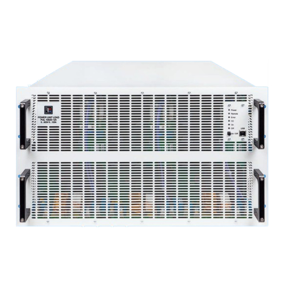
- Page 1 MANUAL EA-PUL 10000 6U Programmable Electronic DC Loads with Energy Recovery © EA Elektro-Automatik in 2023, this information is subject to change without notice 01133009_manual_pul_10000_6u_60kw_en_01...
-
Page 2: Table Of Contents
Remote control via the analog interface 2.1.3 Storage Alarms and monitoring Unpacking and visual check 3.6.1 Definition of terms Installation 3.6.2 Device alarm and event handling © EA Elektro-Automatik in 2023, this information is subject to change without notice 01133009_manual_pul_10000_6u_60kw_en_01... - Page 3 Attention! The part of this document that deals with the handling of features on the control panel is only valid for devices with firmwares “KE: 3.06”, “HMI: 2.05” and “DR: 1.0.2.20” or higher. © EA Elektro-Automatik in 2023, this information is subject to change without notice 01133009_manual_pul_10000_6u_60kw_en_01...
- Page 4 © EA Elektro-Automatik in 2023, this information is subject to change without notice 01133009_manual_pul_10000_6u_60kw_en_01...
-
Page 5: General
Symbol for general notices Warranty EA Elektro-Automatik guarantees the functional competence of the applied technology and the stated performance param- eters. The warranty period begins with the delivery of free from defects equipment. Terms of guarantee are included in the general terms and conditions (TOS) of EA Elektro-Automatik. -
Page 6: Disposal Of Equipment
Maximum voltage of the device in Volt (“10360” = 360 V) Series: 10 = Series 10000 Type identification: PUL = Power Unit Load (electronic load as single power unit) © EA Elektro-Automatik in 2023, this information is subject to change without notice 01133009_manual_pul_10000_6u_60kw_en_01... -
Page 7: Intended Usage
Read and understand the operat- ing guide before using this device. Non-adherence of the instructions in the operating guide can result in serious injury or death. © EA Elektro-Automatik in 2023, this information is subject to change without notice 01133009_manual_pul_10000_6u_60kw_en_01... -
Page 8: Safety
It’s not allowed to run the device on AC sources such as generators or UPS equipment. It must only be • connected to a power grid! © EA Elektro-Automatik in 2023, this information is subject to change without notice 01133009_manual_pul_10000_6u_60kw_en_01... -
Page 9: Responsibility Of The Operator
• before starting work must have read and understood the operating manual • © EA Elektro-Automatik in 2023, this information is subject to change without notice 01133009_manual_pul_10000_6u_60kw_en_01... -
Page 10: Alarm Signals
Only if the current and voltage are supplied by the device as adjustable in the range of 0-100% FS, the device can be consid- ered as fully operational. © EA Elektro-Automatik in 2023, this information is subject to change without notice 01133009_manual_pul_10000_6u_60kw_en_01... -
Page 11: Technical Data
1.8.2 General technical data Display: 6 LED with different colors Controls: 1 pushbutton © EA Elektro-Automatik in 2023, this information is subject to change without notice 01133009_manual_pul_10000_6u_60kw_en_01... -
Page 12: Specific Technical Data
0 - 10 V: ≤0.2%, 0 - 5 V: ≤0.4% Device confi guration Parallel operation Up to 64 units of any power class in series 10000 starting from 5 kW, with Master-Slave bus and Share-Bus © EA Elektro-Automatik in 2023, this information is subject to change without notice 01133009_manual_pul_10000_6u_60kw_en_01... - Page 13 Dimensions (W x H x D) Enclosure: 19“ x 6U x 668 mm (26.3 in) Weight 76 kg (168 lb) Weight with water cooling 82 kg (180 lb) © EA Elektro-Automatik in 2023, this information is subject to change without notice 01133009_manual_pul_10000_6u_60kw_en_01...
- Page 14 Article numbers Standard 01133013 01133014 01133015 Standard + Water Cooling 01663005 01663006 01663007 *1 At 100% power and 100% input voltage BWL = band width limit © EA Elektro-Automatik in 2023, this information is subject to change without notice 01133009_manual_pul_10000_6u_60kw_en_01...
-
Page 15: Views
1.8.4 Views 1.8.4.1 Technical drawings PUL 10000 6U Side view of the air-cooled version shown © EA Elektro-Automatik in 2023, this information is subject to change without notice 01133009_manual_pul_10000_6u_60kw_en_01... - Page 16 6. DC input terminal (copper blades) 7. Share bus connectors to set up a system for parallel connection 8. AC input connector 9. Remote sense connectors © EA Elektro-Automatik in 2023, this information is subject to change without notice 01133009_manual_pul_10000_6u_60kw_en_01...
- Page 17 6. DC input terminal (copper blades) 7. Share bus connectors to set up a system for parallel connection 8. AC input connector 9. Remote sense connectors 10. Water inlet and outlet © EA Elektro-Automatik in 2023, this information is subject to change without notice 01133009_manual_pul_10000_6u_60kw_en_01...
-
Page 18: Control Elements
For quick and easy access to the most important DC input related values when the device isn’t in master-slave mode. This port has reduced functionality compared to the rear port. Status indicators (LED) These six color LEDs show the device status. © EA Elektro-Automatik in 2023, this information is subject to change without notice 01133009_manual_pul_10000_6u_60kw_en_01... -
Page 19: Construction And Function
There are digital, microprocessor controlled components (KE, DR, HMI), which can be target of firmware updates. Share & Sense Power blocks Controller (DR) ≈ ≈ Commu- Commu- nication nication PUL 10000 (KE) (KE) Block diagram © EA Elektro-Automatik in 2023, this information is subject to change without notice 01133009_manual_pul_10000_6u_60kw_en_01... -
Page 20: Scope Of Delivery
Water cooling ment due to exhausted hot air caused by a certain power dissipation. As a side effect, this type of cooling also reduces audible noise. © EA Elektro-Automatik in 2023, this information is subject to change without notice 01133009_manual_pul_10000_6u_60kw_en_01... -
Page 21: The Control Panel (Hmi)
LED “Error” lighting up, indicated an MSP alarm (see section “3.6. Alarms and monitoring” for more information about this alarm) which is normal for not yet initialized slave. © EA Elektro-Automatik in 2023, this information is subject to change without notice 01133009_manual_pul_10000_6u_60kw_en_01... -
Page 22: Usb Port (Rear Side)
The modules can be installed by the user and hence retrofitted anytime. A firmware update of the device may be necessary in order to recognize and support certain modules. Switch your device off before adding or removing modules! © EA Elektro-Automatik in 2023, this information is subject to change without notice 01133009_manual_pul_10000_6u_60kw_en_01... -
Page 23: Analog Interface
The Sense cover must be installed during operation, because there can be hazardous voltage on the sense lines! Reconfiguration on the Sense terminals is only permissible if the device is disconnected from AC supply and all DC sources! © EA Elektro-Automatik in 2023, this information is subject to change without notice 01133009_manual_pul_10000_6u_60kw_en_01... -
Page 24: Master-Slave Bus
The water taps are located on the rear side of the device, also see the rear view drawing in section 1.8.4 . Details about the connection, requirements and use of the water cooling can be found in section 2.3.4 . © EA Elektro-Automatik in 2023, this information is subject to change without notice 01133009_manual_pul_10000_6u_60kw_en_01... -
Page 25: Installation & Commissioning
© EA Elektro-Automatik in 2023, this information is subject to change without notice 01133009_manual_pul_10000_6u_60kw_en_01... -
Page 26: Preparation
1. Disadvantages of this combination: changing the configuration re- quires access via a PC, either on the front or rear USB port. © EA Elektro-Automatik in 2023, this information is subject to change without notice 01133009_manual_pul_10000_6u_60kw_en_01... - Page 27 It could lead to damage or even fire in the wires or connection points. In order to avoid damages and accidents, the existing installation concept must be taken into regard before installing such recovering devices. © EA Elektro-Automatik in 2023, this information is subject to change without notice 01133009_manual_pul_10000_6u_60kw_en_01...
-
Page 28: Installing The Device
The unacceptable positions, as shown below, are also valid for the vertical mount of the device onto a wall (room or inside a cabinet). The required air flow would be insufficient. Acceptable and unacceptable installation positions (air or water cooled, air cooled shown): Standing surface © EA Elektro-Automatik in 2023, this information is subject to change without notice 01133009_manual_pul_10000_6u_60kw_en_01... -
Page 29: Connection To Water Supply (Wc Models)
23.3 24.22 26°C 13.15 14.84 16.26 17.67 18.9 20.09 21.29 22.32 23.32 24.31 25.16 27°C 14.08 15.68 17.24 18.57 19.83 21.11 22.23 23.31 24.32 25.22 26.1 © EA Elektro-Automatik in 2023, this information is subject to change without notice 01133009_manual_pul_10000_6u_60kw_en_01... - Page 30 118.3 120.2 2.3.4.4 Notes The water flow should be started prior to powering the device, but at least prior to switching the DC input on • © EA Elektro-Automatik in 2023, this information is subject to change without notice 01133009_manual_pul_10000_6u_60kw_en_01...
-
Page 31: Connection To Ac Supply
See section “2.3.5.4. Mounting the strain relief” . Figure 10 - Example for an AC cable (wire bundling) © EA Elektro-Automatik in 2023, this information is subject to change without notice 01133009_manual_pul_10000_6u_60kw_en_01... - Page 32 The cross section of that line must be at least the same as with the ground conductor in the AC supply cables. Figure 13 - Grounding point © EA Elektro-Automatik in 2023, this information is subject to change without notice 01133009_manual_pul_10000_6u_60kw_en_01...
-
Page 33: Connection To Dc Sources
90° up or down • space saving in depth • • no bending radius horizontal lead • space saving in height • • large bending radius © EA Elektro-Automatik in 2023, this information is subject to change without notice 01133009_manual_pul_10000_6u_60kw_en_01... -
Page 34: Grounding Of The Dc Terminal
Dangerous voltage on the sense terminals! The sense cover must always be installed. Figure 14 - Example for remote sensing wiring (DC terminal and Sense terminal covers left away for illustrative purposes) © EA Elektro-Automatik in 2023, this information is subject to change without notice 01133009_manual_pul_10000_6u_60kw_en_01... -
Page 35: Installation Of An Interface Module
On the bottom side of the module are two plastic nibs which must click into the green board (PCB) so that the module is properly aligned on the rear wall of the device. © EA Elektro-Automatik in 2023, this information is subject to change without notice 01133009_manual_pul_10000_6u_60kw_en_01... -
Page 36: Connection Of The Analog Interface
Refer to “2.3.13. Initial commission” . Only after successful checking of the device as listed may it be operated as usual. © EA Elektro-Automatik in 2023, this information is subject to change without notice 01133009_manual_pul_10000_6u_60kw_en_01... -
Page 37: Operation And Application
1.8.3 . If less voltage than U is supplied, the load proportionally draws less current, which can be calculated easily. Imax See principle view to the right. I(A) © EA Elektro-Automatik in 2023, this information is subject to change without notice 01133009_manual_pul_10000_6u_60kw_en_01... -
Page 38: Current Regulation / Constant Current / Current Limiting
The value to achieve the expected result is not defined and has to be found out. We recommend: 360 V model: 100uF...470uF 750/920/1000 V models: 22uF...100uF 500 V model: 47uF...150uF 1500/2000 V models: 4.7uF...22uF © EA Elektro-Automatik in 2023, this information is subject to change without notice 01133009_manual_pul_10000_6u_60kw_en_01... -
Page 39: Alarm Conditions
DC input reaches the adjusted OPP limit. • This function serves to protect the connected external source so it’s not overloaded and possibly damaged due to an exces- sive power. © EA Elektro-Automatik in 2023, this information is subject to change without notice 01133009_manual_pul_10000_6u_60kw_en_01... -
Page 40: Share Bus Fail
In case the system is initialized only later on, the slave will signal SF. The alarm must be acknowledged after the cause of the alarm has been removed. © EA Elektro-Automatik in 2023, this information is subject to change without notice 01133009_manual_pul_10000_6u_60kw_en_01... -
Page 41: Manual Operation
DC input related parameters via the front USB port. The button can also be used to acknowledge device alarms signaled by LED “Error”. Configuration of parameters via one of the USB ports is considered as remote control and is thus described in 3.5 . © EA Elektro-Automatik in 2023, this information is subject to change without notice 01133009_manual_pul_10000_6u_60kw_en_01... -
Page 42: Remote Control
INPut[:STATe] [SOURce:]VOLTage:LIMit:HIGH? INPut[:STATe]? [SOURce:]VOLTage:LIMit:LOW [SOURce:]CURRent [SOURce:]VOLTage:LIMit:LOW? [SOURce:]CURRent? [SOURce:]VOLTage:PROTection[:LEVel] [SOURce:]CURRent:LIMit:HIGH [SOURce:]VOLTage:PROTection[:LEVel]? [SOURce:]CURRent:LIMit:HIGH? STATus:OPERation? [SOURce:]CURRent:LIMit:LOW STATus:QUEStionable? [SOURce:]CURRent:LIMit:LOW? SYSTem:ALARm:ACTion:PFAil [SOURce:]CURRent:PROTection[:LEVel] SYSTem:ALARm:ACTion:PFAil? [SOURce:]CURRent:PROTection[:LEVel]? SYSTem:ALARm:COUNt:OCURrent? [SOURce:]POWer SYSTem:ALARm:COUNt:OPOWer? [SOURce:]POWer? SYSTem:ALARm:COUNt:OTEMperature? [SOURce:]POWer:LIMit:HIGH SYSTem:ALARm:COUNt:OVOLtage? © EA Elektro-Automatik in 2023, this information is subject to change without notice 01133009_manual_pul_10000_6u_60kw_en_01... -
Page 43: Interface Monitoring
The timeout of the monitoring can be changed anytime via remote control; the new value would only be valid after the • current timeout has elapsed The interface monitoring doesn’t deactivate the Ethernet connection timeout, so these two timeouts can overlap • © EA Elektro-Automatik in 2023, this information is subject to change without notice 01133009_manual_pul_10000_6u_60kw_en_01... -
Page 44: Remote Control Via The Analog Interface
The same is required for PF and OT in case the related EA Power Control settings Other->DC input/output state after PF alarm or Other->DC input/output state after OT alarm are set to Off. © EA Elektro-Automatik in 2023, this information is subject to change without notice 01133009_manual_pul_10000_6u_60kw_en_01... - Page 45 0...100% of a value when working in the 10 V range. In the 5 V range this resolution halves. Due to tolerances, the truly achievable resolution can be slightly lower. © EA Elektro-Automatik in 2023, this information is subject to change without notice 01133009_manual_pul_10000_6u_60kw_en_01...
- Page 46 -> REM-SB level” being set to “Normal”, it requests to switch the DC input on. So when activating remote control, the DC input will instantly switch on. © EA Elektro-Automatik in 2023, this information is subject to change without notice 01133009_manual_pul_10000_6u_60kw_en_01...
- Page 47 Reading actual values The AI provides the DC input values as current and voltage monitor. These can be read using a standard multimeter or similar. © EA Elektro-Automatik in 2023, this information is subject to change without notice 01133009_manual_pul_10000_6u_60kw_en_01...
-
Page 48: Alarms And Monitoring
Acknowledging a PF alarm during runtime can only occur approx. 15 seconds after the cause of the alarm has gone. Switching the DC input on again requires another approx. 5 seconds of waiting time. © EA Elektro-Automatik in 2023, this information is subject to change without notice 01133009_manual_pul_10000_6u_60kw_en_01... - Page 49 These events shall not be confused with alarms such as OT and OVP which are for device protection. User defined events can, however, if set to action “Alarm”, switch off the DC input and thus protect the source, like a sensitive electronic application. © EA Elektro-Automatik in 2023, this information is subject to change without notice 01133009_manual_pul_10000_6u_60kw_en_01...
-
Page 50: Other Applications
DC minus poles of all units have to be connected, because DC minus is the reference for the share bus. Principle view (without source): Share bus connection Master-slave bus © EA Elektro-Automatik in 2023, this information is subject to change without notice 01133009_manual_pul_10000_6u_60kw_en_01... - Page 51 51 kW, which is even less than the single 60 kW unit can provide. However, when switching to the 60 kW unit as master, the system will result in 63 kW total power. © EA Elektro-Automatik in 2023, this information is subject to change without notice 01133009_manual_pul_10000_6u_60kw_en_01...
- Page 52 With any of the other available interfaces, the translation of values is to be done by the software. © EA Elektro-Automatik in 2023, this information is subject to change without notice 01133009_manual_pul_10000_6u_60kw_en_01...
- Page 53 OCP alarm though the global OCP limit of the MS system was not reached. The same can occur with the OPP alarm. © EA Elektro-Automatik in 2023, this information is subject to change without notice 01133009_manual_pul_10000_6u_60kw_en_01...
-
Page 54: Series Connection
“see” almost the full DC input voltage which will most likely damage the DC input stage, as well as insulation. © EA Elektro-Automatik in 2023, this information is subject to change without notice 01133009_manual_pul_10000_6u_60kw_en_01... -
Page 55: Service And Maintenance
Newly implemented features may require an updated documentation (user manual and/or programming guide, as well as • LabVIEW VIs), which is often delivered only later, sometimes significantly later © EA Elektro-Automatik in 2023, this information is subject to change without notice 01133009_manual_pul_10000_6u_60kw_en_01... -
Page 56: Trouble-Shooting Device Problems
As an additional measure include fuses in line with the DC cables which could attenuate or even prevent damage to the device. © EA Elektro-Automatik in 2023, this information is subject to change without notice 01133009_manual_pul_10000_6u_60kw_en_01... -
Page 57: Contact And Support
Telephone EA Elektro-Automatik GmbH Technical support: Switchboard: +49 2162 / 37850 Helmholtzstr. 31-37 support@elektroautomatik.com Support: +49 2162 / 378566 41747 Viersen All other topics: Germany ea1974@elektroautomatik.com © EA Elektro-Automatik in 2023, this information is subject to change without notice 01133009_manual_pul_10000_6u_60kw_en_01... - Page 58 9845 Via Pasar 41747 Viersen CA, 92126, San Diego Phone: +49 2162 3785 - 0 Phone: +1 (858) 281 2265 Fax: +49 2162 16230 ea1974@elektroautomatik.com sales@elektroautomatik.com www.elektroautomatik.com www.eapowered.com © EA Elektro-Automatik in 2023, this information is subject to change without notice 01133009_manual_pul_10000_6u_60kw_en_01...
Need help?
Do you have a question about the EA-PUL 10000 6U and is the answer not in the manual?
Questions and answers