AVer CAM520 Pro3 User Manual
Hide thumbs
Also See for CAM520 Pro3:
- User manual (46 pages) ,
- Quick start manual (88 pages) ,
- Quick start manual
Table of Contents
Advertisement
Quick Links
Advertisement
Table of Contents

Subscribe to Our Youtube Channel
Related Manuals for AVer CAM520 Pro3


Summary of Contents for AVer CAM520 Pro3
- Page 1 CAM520 Pro3 User Manual...
- Page 2 Federal Communications Commission Statement NOTE: This equipment has been tested and found to comply with the limits for a Class A digital device, pursuant to part 15 of the FCC Rules. These limits are designed to provide reasonable protection against harmful interference when the equipment is operated in a commercial environment. This equipment generates, uses, and can radiate radiofrequency energy and, if not installed and used in accordance with the instruction manual, may cause harmful interference to radio communications.
- Page 3 Remote Control Battery Safety Information Store batteries in a cool and dry place. Do not throw away used batteries in the trash. Properly dispose of used batteries through specially approved disposal methods. Remove the batteries if they are not in use for long periods of time. Battery leakage and corrosion can damage the remote control.
- Page 4 © 2023 AVer Information Inc. All rights reserved. | May x, 2023 All rights of this object belong to AVer Information Inc. Reproduced or transmitted in any form or by any means without the prior written permission of AVer Information Inc. is prohibited. All information or...
- Page 5 Tel: +81 (0) 3 5989 0290 テクニカル・サポート: https://jp.aver.com/technical-support Vietnam Branch Office Công ty TNHH AVer Information (Việt Nam) Tầng 5, 596 Nguyễn Đình Chiểu, P.3, Quận 3, Thành phố Hồ Chí Minh 700000, Việt Nam Tel: +84 (0)28 22 539 211...
-
Page 6: Table Of Contents
Contents Package Contents ......................1 Product Introduction ......................2 Overview .......................... 2 LED Indicator ........................2 Remote Control........................ 3 Pan and Tilt Angle ......................6 Installation .......................... 7 Device Connection......................7 Power Connection ......................8 HDMI Connection ......................9 RS-232 Connection ....................... 10 Wall Mount Installation .................... - Page 7 SmartFrame Preset Point ..................32 Auto Focus ......................33 Camera Focus ...................... 33 Home Position ...................... 33 Sleep Position ...................... 33 Sleep Timer ......................34 On Screen Menu ....................34 Camera Binding ....................34 Save Preset......................34 Image Settings ......................35 Image Flip ......................
- Page 8 Allow Providing of anonymous usage data ............49 Information ......................49 PTZApp 2 ........................... 50 Install PTZApp 2 ......................50 Use PTZApp 2 with USB Devices .................. 51 Use PTZApp 2 with a Virtual Stream ................59 EZLive ..........................60 Use AVer EZLive ......................60...
-
Page 9: Package Contents
Mini DIN 8 to D-Sub 9 Ceiling Mount HDMI Cable (3m) Foldable TV Mount Cable (Upside Down Installation) *Optional Accessories will vary depending on the country where it is sold. **To mount on ceiling, please purchase ceiling mount kit from AVer. -
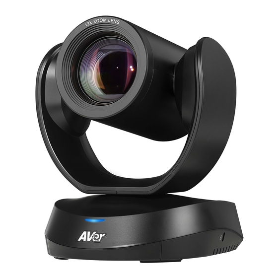
Page 10: Product Introduction
Product Introduction Overview 4 5 6 7 Status LED USB 3.1 Type B Port PoE Port* IR Sensor RS-232 In/Out Port Kensington Lock HDMI Port 12V DC Power Jack *Power over Ethernet (PoE), compatible with IEEE 802.3AT. Please use CAT 5e FTP cable (not included). -
Page 11: Remote Control
1. Camera Select One remote control can control up to 3 AVer USB series cameras. You can use AVer PTZApp 2 or IP web page to set numbers associated with each camera, and then select which camera you would like to control using the remote. - Page 12 function and select “Off”. [Notes] Default is Manual Framing. SmartFrame deploys face and body detection technology. People wearing masks and side facial profiles can still be detected. The maximum detection distance is 7~10 meters away from the camera. Camera will track people while moving.
- Page 13 button and preset position button 0-9 to load a saved camera position. Repeat steps if needed. Preset position buttons are used in 7. Preset Position/Number conjunction with the Preset button to Buttons save positions. There are a total of 10 presets.
-
Page 14: Pan And Tilt Angle
Pan and Tilt Angle... -
Page 15: Installation
Connect the power to the CAM520 Pro3; power indicator will light up and camera head will rotate. Install PTZApp 2 on laptop or PC that is connected with CAM520 Pro3. The app can be used to adjust and setup the parameters of the camera (refer to the section of PTZApp 2). -
Page 16: Power Connection
Power Connection The power supply can be plugged into the wall outlet or drawn from PoE switch (Ethernet). Wall outlet [Note] To ensure stability of IP video streaming, please use CAT 5e FTP cable (not included). -
Page 17: Hdmi Connection
HDMI Connection Connect with TV or monitor through the HDMI port to display camera video on the screen. -
Page 18: Rs-232 Connection
RS-232 Connection Camera RS-232 Port Pin Definition Mini DIN9 Function I/O Type Signal Description PIN # Output Data Terminal Ready Input Data Set Ready VISCA IN Output Transmit Data Input Receiver Data Output Data Terminal Ready Input Data Set Ready VISCA OUT Output Transmit Data... - Page 19 Computer/Keyboard Controller and Camera Connection Direct Connection If users do not use AVer RS-232 adapter cable, please refer to the pin connection shown below. Mini DIN 9 to DB9 cable Camera controller Camera Camera controller or PC (Mini DIN 9) (DB9) 1.
- Page 20 Use the supplied RS-232 mini DIN 9 to mini DIN 8 cable RS232 mini DIN 9 to mini DIN 8 cable** VISCA IN (female) Mini DIN 8 to DB9 cable* VISCA OUT (female) Camera controller Camera controller or PC Camera (DB9) (Mini DIN 8) 1.
- Page 21 * Mini DIN 8 to D-Sub 9 (DB9) cable 064AOTHERCGN is an optional item. ** RS-232 mini DIN 9 to mini DIN 8 Cable Pin Definition Mini DIN 9 Connect to an AVer camera Mini DIN 8 (in) Connect to the next camera...
- Page 22 Camera Cascade Connection Direct Connection If users do not use AVer RS-232 adapter cable, please refer to the pin connection shown below for cascading cameras. Total can connect up to 7 cameras. Camera 1 Camera 2 (Mini DIN 9) (Mini DIN 9) 1.
- Page 23 Connect camera with AVer mini DIN 9 to mini DIN 8 adapter cable. Connect the mini DIN 8 female side to male mini DIN 8 Visca cable (Users have to buy it in the market) and then connect AVer mini DIN 9 to mini DIN 8 adapter cable again to connect to next camera.
-
Page 24: Wall Mount Installation
Wall Mount Installation 1. Use the drilling paper included in the package to drill the holes in the wall where the user wants to mount the camera. 46.00[1.81] Ø 5.50[Ø 0.22] 51.00[2.01] P/N: 303AU340-AGR 2. Use the screws (not included) to secure the L-mount bracket on the wall. - Page 25 3. Then, assemble the L-mount brackets with screws (included in package). Screw size: M4 x8mm (x2) 4. After assembling the L-mount brackets, use the screws (not included) to secure the lower part of L-mount brackets on the wall. Screw For Cement wall: M4 x20mm self-tapping screws (x2) + Plastic conical anchor For Wooden wall: M4 x20mm self-tapping screws (x2)
- Page 26 5. Pass the cables through the hole on the L-mount bracket and connect the cables to corresponding connection ports. 6. Use the remaining screws (included in package) to secure the camera on the L-mount bracket. 1/4”-20 L=7.5mm (x2) Screw:...
-
Page 27: Ceiling Mount Installation
Ceiling Mount Installation Install the provided screw underneath the camera but do not tighten. 2. Turn the camera to right side. Pass cables through A or B hole first. Connect cables with camera. - Page 28 4. Turn the camera to face the front side. Install the second screw and tighten both screws. Find suitable screws to fix the camera mount to the ceiling.
-
Page 29: Secure The Cables
Secure the Cables The USB and RS-232 cables have a screw on the cable for securing cable on the camera. Install the cable first and tighten the screw to secure the cable. [Note] Make sure the cable is well connected to the connector on the camera before securing the cable. -
Page 30: Operating The Camera
Wirecast, XSplit, etc.) on your PC or laptop. Set the CAM520 Pro3 camera as the primary camera for your video application (refer to your video application user guide). You can now make your call. [Note] The CAM520 Pro3 is a plug-and-play conference camera. The system requires no special drivers, but we do recommend installing the PTZApp 2 for a better user experience. - Page 31 Input the new account, password and click Login, you will be prompted with a setting for sharing the non-personal data with AVer, such as the functions used and firmware versions of the AVer devices. Click to enable sharing the usage data with AVer and then click Done.
- Page 32 * For information on how to install and use the PTZApp 2, refer to the PTZApp 2 section in this user manual. ** To support IP address changes in groups, user can download AVer IP Finder app. 1. Download the IP Finder from https://www.aver.com/download-center...
-
Page 33: Web Settings
Web Settings CAM520 Pro3 supports Ethernet connection; users can enter the IP address into the web browser to connect to the camera for detail settings. First Time Login To find the IP address of the camera, please refer to “Make a connection through the Browser”... -
Page 34: Live Screen Operation
Live Screen Operation User can control the camera direction, zoom in/out, and preset selection. [Notes] The system will force the previous login to log out, when there is a second login. If the web page is idle without any request for more than 4 hours, user will be logged out. ... -
Page 35: Ptz Control
PTZ Control You can use the PTZ Control page to configure up to 10 preset positions. In live screen, use ▲ , ▼ , , and zoom in/out buttons to adjust the camera screen view to desired position. Select “Set” button and click on the preset number to save the preset. The system will capture the preset screen view and display in preset number frame. - Page 36 After setting up the preset positions, you can start performing the function. Select the “Load” button and then click on the preset numbers, the live screen will move to the preset screen view.
-
Page 37: Camera Settings
Camera Settings The video icon is to turn on camera live view while adjusting any settings. IP icon shows the IP address of the camera. Live screen preview Click the icon to show/hide people count number & stream interval. Click the icon to hide people count and the time interval of enabling the live streaming of the camera. -
Page 38: Tracking Mode
Tracking Mode Select Setting > Camera > Tracking Mode > Off, Manual Frame, Auto Frame, Preset Framing or Smart Composition. Off: Tracking mode is disabled. Manual Frame: User one-click SmartFrame button and camera will adjust view angle to fit all participants in screen. -
Page 39: Camera Moving Speed
Overlap beginning & end of each zone [Note] CAM520 Pro3 frames people in masks or any facial profile up to 7~10 meters away! Smart Composition: Frame up to 6 people, when 7 or above appear in the image, camera will return to wide view. -
Page 40: Framing Speed
Framing Speed Select Setting > Camera > Framing Speed > Slow Speed, Middle Speed (default), or High Speed. When in auto framing or preset framing mode, camera will automatically frame people if they stand still without moving for 1~5 seconds. ... -
Page 41: Auto Focus
Auto Focus Set auto focus mode. First select Setting > Camera > Camera Focus > Auto. Select Setting > Camera > Auto Focus > PTZ or Continuous. PTZ: Click the button (such as pan, tilt, or zoom in/out) to adjust focus once. ... -
Page 42: Sleep Timer
Select Setting > Camera > Camera Binding > Camera1, Camera2, or Camera3. [Note] When camera binding is off, press camera 1, 2, or 3 button on the remote control can control all the AVer USB camera nearby you. Save Preset Enable/disable “save preset”... -
Page 43: Image Settings
Image Settings Image Flip Flip the image vertically for upside down installation. Select Setting > Image > Image Flip > Off or On. Image Mirror Flip the image horizontally. Select Setting > Image > Image Mirror > Off or On. In back light environment, enable WDR to improve the brightness of image. -
Page 44: Flicker Decrease On Ifp/Monitor
Flicker Decrease on IFP/Monitor This is to ensure fluid content capture on IFP monitor Select Setting > Image > Flicker Decrease on IFP / Monitor > Off or On. [Note] While in WDR mode, flicker decrease function will be disabled. Frequency Select the frequency of the camera. -
Page 45: Brightness
Brightness Adjust the value of brightness. Select Setting > Image > Brightness > 1 ~ 9. Sharpness Adjust the value of sharpness. Select Setting > Image > Sharpness > Off, Low, Middle, or High. Saturation Adjust the value of saturation. Select Setting >... -
Page 46: Enlarge Total Zoom Up To 36X
30fps is with much better image quality than 60fps. Unless you want to shoot fast moving objects, please use 30fps. RS-232 Settings When CAM520 Pro3 connects with PTZ camera controller through the RS-232 port, please setup ADDR, Baud Rate, Protocol, and Visca Over IP settings. Select Setting > RS-232. -
Page 47: Video Format Settings
Video Format Settings H.264 Profile While in live broadcasting, user can choose preferable profile to get best streaming quality. Select Video Format > H.264 Profile > Baseline Profile or High Profile. IP Stream Resolution only Set up the resolution for IP stream. Not supported for USB video stream. Select Video Format >... -
Page 48: Rtsp
For Facebook live broadcasting, it’s suggested to choose less than 4Mbps to ensure smooth streaming. RTSP To use RTSP player connecting to the camera, please enter the RTSP URL which displays on the web in your application such as VLC, PotPlayer, or Quick Time. Select On/Off to enable/disable password requirement while opening RTSP. -
Page 49: Rtmp
RTMP Set up for uploading the camera’s live view to the broadcasting platform (e.g. YouTube). Select Video Format > RTMP. 1. Locate the RTMP server URL and stream key from the broadcasting platform and enter in Server URL and Stream Key fields. 2. -
Page 50: Network Settings
Network Settings Hostname User can set a hostname. The hostname only allows numeric and alphabetic characters. Select Network > Hostname. Click the pencil icon to enter hostname. DHCP Enable/disable DHCP function. Select Network > DHCP > Off or On. -
Page 51: Static Ip
Static IP Assign a fixed IP address to the camera. Please turn off the DHCP function. 1. Select Network > DHCP > Off. 2. Click pencil icon and enter the IP Address, Gateway, NetMask, and DNS in the corresponding fields. 3. -
Page 52: System Settings
Update the camera’s firmware. Select System > FW Update > Auto Update or Manual Update. Auto Update: The system will check firmware version from AVer server and request to update. Manual Update: To update the firmware from specific location. -
Page 53: Factory Default
Factory Default Reset the camera back to factory default setting. 1. Select System > Factory Default > Reset. 2. User can choose to keep current IP address or back to default. 3. Select Continue to reset back to factory default. [Note] When factory default is activated, the password of Webpage login will not be set to default. -
Page 54: Change Password
Change Password Change the web login password. The default password is “aver4321”. 1. Select System > Change Password > Change WEB Access Password. 2. Enter the old account and password. Select Continue. 3. Enter the new account and password. Select Continue to save the new setting. 4. -
Page 55: Ssl Certificate
SSL Certificate Import the SSL certificate from specific location. 1. Select System > SSL Certificate > Import. 2. Select the type by clicking “+”. 3. Direct the file location. 4. Select Import. [Note] If you want to disable SSL certificate function, please use PTZApp 2 to switch off this function. Date Format Select the date format. -
Page 56: Time Correction Mode
Time Correction Mode Adjust time automatically or manually. Select System > Time Correction Mode > Auto or Manual. Auto: The system time will be set by NTP server on the network. Click the pencil icon of NTP Server and enter the URL of NTP server. Select the Time Zone. Select NTP Update to save setting. -
Page 57: Allow Providing Of Anonymous Usage Data
Allow Providing of anonymous usage data You can enable this function to help AVer continuously improve our products and services. Please visit AVer’s privacy policy for more information. https://www.aver.com/privacy Select System > Allow Providing of anonymous usage data > Off or On. -
Page 58: Ptzapp 2
PTZApp 2 In PTZApp 2, user can change the IP address setting of CAM520 Pro3, configure the parameters of the camera, set up AI tracking functions and some advanced image settings, pan, tilt, and zoom the camera. Install PTZApp 2 Please go to https://www.aver.com/download-center... -
Page 59: Use Ptzapp 2 With Usb Devices
WDR, brightness, and sharpness feature. 3. Launch PTZApp 2 ( ) and it will open in Chrome browser automatically. Choose “USB device” and connect CAM520 Pro3 to PC/laptop with USB cable When the camera is detected, the product card will show up. - Page 60 Set up IP address. The camera default IP address is 192.168.1.168. Click pencil icon ( ) to edit IP address. Click the setting icon to change Language, Hotkey Control, and PTZApp 2 Version. Language: Select desired language and click the check icon to confirm the selection.
- Page 61 Hotkey Control: User can control the camera by using keyboard. This is a general list for all AVer USB Cameras. Backlight control equals to WDR function in CAM520 Pro3. PTZApp Update: Get current PTZApp 2’s version number and do auto update here.
- Page 62 Information: Click the drop-down triangle icon to review the information of camera. To minimize the information, click the triangle again or the model name. Camera: Click the camera icon to view the camera live view. Click the X icon to close the camera live view. If the live video did not appear, please check the camera and the laptop/PC connection to make sure all are correct and well connected.
- Page 63 Full Screen: PTZApp 2 can switch to full screen mode. Click “ ” icon and video screen will switch to full screen mode. In full screen mode, user can use direction panel to control camera direction. Click “ ” icon to go back to normal screen view. The resolution of full screen mode is 1080p/ 30fps.
- Page 64 People Count and Stream Interval: Click the icon to show people count number and stream interval. Click the icon to hide the stream interval. Control Panel: To control the camera direction, zoom in and out during your video call.
- Page 65 Setting: Click “Setting” button to set up parameters of the camera and speakerphone. Click arrow icon to leave the Setting page. PTZ Control: Use control panel to set up preset positions. Since most of operations are the same as web page, refer to <PTZ Control>...
- Page 66 10. PTZApp 2 Quit & Restore: To quit the application, right-click the icon on the system tray and select “Quit”. If you can’t launch PTZApp 2 right after installation, please right –click the icon and choose “Restore”.
-
Page 67: Use Ptzapp 2 With A Virtual Stream
Virtual Stream technology uses an RTSP stream. If you set a password for RTSP, you will be asked to provide that password while enabling this function. Launch VC software (e.g. Zoom, Teams, Skype) and choose AVer USB VCam as the video source to start collaborating. -
Page 68: Ezlive
EZLive Please go to http://www.aver.com/download-center to download the AVer EZLive software. After downloading, double-click on the file and follow the on-screen instructions to complete the installation. Use AVer EZLive During a video call, EZLive can help user to do: (1) Camera ePTZ (2) Volume control for the speaker connected (3) Capture camera’s still images...
Need help?
Do you have a question about the CAM520 Pro3 and is the answer not in the manual?
Questions and answers