AVer TR333V2 User Manual
Ai auto tracking ptz camera
Hide thumbs
Also See for TR333V2:
- User manual (78 pages) ,
- User manual (65 pages) ,
- User manual (75 pages)

Related Manuals for AVer TR333V2


Summary of Contents for AVer TR333V2
- Page 1 AI Auto Tracking PTZ Camera TR333V2 / TR323NV2 / TR313V2 / TR311HWV2 PTC330UV2 / PTC320UNV2 / PTC320UV2 / PTC310UV2 / PTC310HWV2 User Manual...
- Page 2 Federal Communications Commission Statement NOTE: This equipment has been tested and found to comply with the limits for a Class A digital device, pursuant to part 15 of the FCC Rules. These limits are designed to provide reasonable protection against harmful interference when the equipment is operated in a commercial environment.
- Page 3 © 2022 AVer Information Inc. All rights reserved. | June 7, 2022 All rights of this object belong to AVer Information Inc. Reproduce d or transmitted in any form or by any means without the prior written permission of AVer Information Inc. is prohibited. All information or specifications are subject to change without prior notice.
- Page 4 WARNING To reduce the risk of fire or electric shock, do not expose this appliance to rain or moisture. Warranty will be void if any unauthorized modifications are done to the product. Do not drop the camera or subject it to physical shock . ...
- Page 5 Tel: +81 (0) 3 5989 0290 テクニカル・サポート: VCInfo.JP@aver.com Vietnam Branch Office Công ty TNHH AVer Information (Việt Nam) Tầng 5, 596 Nguyễn Đình Chiểu, P.3, Quận 3, Thành phố Hồ Chí Minh 700000, Việt Nam Tel: +84 (0)28 22 539 211...
-
Page 6: Table Of Contents
System ................25 Web Setup ..................... 26 Access the Web Interface of the Camera ........... 26 Accessing the Camera via AVer IPCam Utility ....26 Accessing the Camera via AVer PTZ Management ... 28 Live View ..................... 29 Camera Control ..............29 Preset ................. - Page 7 Image Process ..............33 Video & Audio ..................34 Network ....................36 Tracking Settings ................39 Presenter Mode ..............41 Zone Mode ................. 46 Hybrid Mode ............... 48 Gesture ................50 NDI ...................... 52 System ....................54 Appendix ......................56 VISCA RS-232 Command Table ..............
-
Page 8: Package Contents
Package Contents Package Contents Ceiling Mount Camera Unit Drilling Paper Quick Start Guide Bracket (x2) 1/4”-20 L=6.5mm M2 x 4mm Power Adapter & Cable Fixing Plate Screw (x3) Power Cord Screw (x2) M3 x 6mm DIN8 to D-Sub9 RS-232 In/Out Remote Control Screw (x3) Cable... -
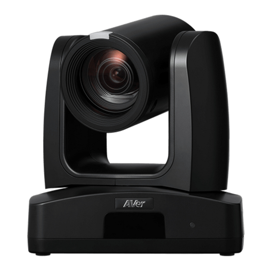
Page 9: Product Introduction
Product Introduction Overview (5) (6) (7) (8)(9) (11) (10) (12) (1) Tally Lamp (5) PoE+ IEEE 802.3AT (9) Audio In* (2) IR Sensor (6) RS-232 Port (10) HDMI Port (3) LED Indicator (7) RS-422 Port (11) 3G-SDI** (4) Kensington Lock (8) USB 3.0 Port (Type-B) (12) DC Power Jack *Line input level: 1Vrms (max.). -
Page 10: Pan And Tilt Angle
Pan and Tilt Angle... -
Page 11: Dimensions
Dimensions 80mm 156.5mm 145mm 180mm 161.3mm 145mm 156.5mm 161.3mm 180mm... - Page 12 Ceiling Mount 80mm 104mm 153mm 161.3mm 180mm 200.8mm...
- Page 13 Wall Mount 180mm 161.3mm 206mm 263.2mm...
-
Page 14: Device Connection
Device Connection Joystick (Camera Control) Laptop (Management/Presentation/ Video Conference) Microphone Audio Input RS232, RS422 or IP 3G-SDI Monitor/TV PoE+ (Display) HDMI Lecture Capture System Camera (Record) Web Application (Remote Management) PoE Connection Connect the camera to the router or switch through the PoE+ port. [Note] Only support IEEE 802.3AT PoE+ standard. -
Page 15: Rs-232 And Rs-422 Connection
RS-232 and RS-422 Connection Connect through the RS-232 or RS-422 for camera control. RS232 RS232 (VISCA) Cable (Not Included) Joystick Laptop... - Page 16 ● RS-232 Port Pin Definition Mini DIN9 Function I/O Type Signal Description PIN # Output Data Terminal Ready Input Data Set Ready VISCA IN Output Transmit Data Input Receiver Data Output Data Terminal Ready Input Data Set Ready VISCA OUT Output Transmit Data Input...
- Page 17 ● RS-232 mini DIN9 to mini DIN8 Cable Pin Definition Mini DIN8 Cable Pin Definition Signal...
- Page 18 ● Din8 to D-Sub9 Cable Pin Definition...
- Page 19 RS-422 [Note] Use cat5e splitter for multi-camera connection. RS-422 Pin Cat5e splitter pin assignment: Camera Camera/Joystick Camera/Joystick...
-
Page 20: Audio Input Connection
Audio Input Connection Connect the audio device for audio receiving. [Note] Line input level: 1Vrms (max.). Mic input level: 50mVrms (max.); Supplied voltage: 2.5V. Microphone Audio Mixer... -
Page 21: Video Output Connection
Video Output Connection HDMI Use the HDMI cable to connect with monitor or TV for video output. HDMI Cable Monitor/TV 3G-SDI Connect to 3G-SDI monitor for video output. 3G-SDI Cable (Not Included) SDI Monitor [Notes] HDMI and 3G-SDI monitors can be connected to camera and output live video simultaneously; Assuming HDMI monitor is well connected before the camera turned on, the OSD menu will be displayed on HDMI monitor in default. - Page 22 Cable Fixing Plate Installation Secure the cable fixing plate to the camera with 3 M2 x 4mm screws (included in the package). Use 4 cable ties to secure the cables and cable Plug in cables. fixing plate.
- Page 23 Ceiling Mount Installation 1. Secure the mount bracket on the ceiling. 2. Install the mount bracket on the camera. Screw: 4 screws, M4 x 10mm (Not Screw: 2 screws, 1/4"-20 L=6.5mm (Included Included in the package) in the package) 3. Slide the mount bracket with the camera 4.
-
Page 24: Camera Installation
Camera Installation Angle A: less than 30˚ Height B: 2~3m from floor Distance C: longer than 3m away from podium Position: center of classroom Distance between the camera and tracking target (presenter): Optical zoom ratio ability Upper body size Full body size 3~16m... -
Page 25: Remote Control
Remote Control (10) (12) (11) (14) (13) (15) (17) (16) (19) (20) (18) (21) (22) (24) (23) Name Function Turn the unit on/standby. (1) Power Open and exit the OSD menu. (2) Menu CAM1 to CAM3 button (3) Camera Select Select a camera to operate. - Page 26 Name Function Zoom in/out slowly. (13) Zoom +/- Enable manual focus. Use Far/Near to adjust the focus. (14) MF/Far/Near Zoom in/out fast. (15) Zoom Fast +/- Pan-Tilt speed adjustment. (16) Pan-tilt Fast/Slow Auto focus. (17) AF Auto Tracking on/off. (18) Auto Tracking Freeze the live image.
-
Page 27: Set Up The Camera
Set Up the Camera OSD Menu You can use the supplied Remote Control to operate the OSD Menu. Press the button to call out the OSD menu and use the ▲ , ▼ , , and buttons to operate the OSD menu. IP Address Setup Static IP 1. -
Page 28: Dhcp
DHCP 1. Press the button on the remote control to call out the OSD menu. 2. Go to Network > DHCP > On. 3. After turning the DHCP on, the user can go to System > Information to view the IP address. -
Page 29: Osd Menu Tree
OSD Menu Tree Camera Set up camera parameters – Exposure Mode, White Balance, Pan Tilt Zoom, Noise Reduction, Saturation, Contrast, Sharpness, Mirror and Flip. Layer Layer Layer Layer Layer Camera Exposure Mode Full Auto Exposure Value -4/-3/-2/-1/0/1/2/3/4 Gain Limit Level 24dB/27dB/30dB/33dB/36dB /39dB/42dB Slow Shutter... - Page 30 Layer Layer Layer Layer Layer Camera White Balance Auto Indoor Outdoor One push Manual R Gain (0-255) B Gain (0-255) Pan Tilt Zoom Preset Speed 5/25/50/100/150/ Digital Zoom Off/On Digital Zoom x2-x12 Limit Pan/Tilt Slow Off/On Noise Reduction Off/Low/Mediu m/High Saturation 0-10 Contrast...
-
Page 31: Video Output
Video Output Select video resolution (2160p is only supported on certain models). Layer Layer Layer Video Output Priority Mode 2160p/1080p Frequency 50 Hz/59.94 Hz/60 Hz Resolution 2160P/30, 2160P/29.97, 1080P/60, 1080P/59.94, 1080P/30, 1080P/29, 1080I/60, 1080I/59, 720P/60, 720P/59.94, 2160P/25, 1080P/50, 1080P/25, 1080I/50, 720P/50 Network Set up IP mode –... -
Page 32: System
System Status OSD: Enable/disable Preset status (Save Preset, Call Preset, Cancel Preset) display on the screen. Camera Selector: Set the camera ID 1~3 for using remote control on multiple cameras control (also see No.3 Camera Select in Remote Control chapter). ... -
Page 33: Web Setup
Connect the camera from a remote site through the internet. Access the Web Interface of the Camera To access the Web interface of the camera, you have to find the IP address of the camera using AVer IPCam Utility or AVer PTZ Management software. - Page 34 5. Login with the new ID/Password, the Web interface of the camera will be displayed (Chrome browser). Please refer to the Live View chapter for more details. [Note] If IPCam utility cannot find the camera, please check the following: 1. Please make sure the Ethernet connection of the camera is well connected. 2.
-
Page 35: Accessing The Camera Via Aver Ptz Management
Accessing the Camera via AVer PTZ Management To find the IP address of your cameras using the AVer PTZ Management, follow the steps below. 1. Download the AVer PTZ Management software from https://www.aver.com/download-center 2. Download the Windows program and install it. -
Page 36: Live View
Live View You can control the camera and operate the Preset functions using this page. Camera Control Click the Camera Control tab to display the panel below for operation. Pan-Tilt-Zoom Control , and to navigate the camera view. Adjust the Pan Speed and Tilt Speed if necessary. -
Page 37: Preset
Focus Auto Focus : Click for the camera to perform the auto focus. : Click to manually adjust the focus. You can use the Focus + and Focus – Manual Focus buttons to adjust the focus. One Push Focus : Click to automatically adjust the focus once. Focus Near Limit: Set up the focus distance limit. - Page 38 To perform the go to preset positions: 1. Input a preset number (0~255) in the Load Preset column or click a preset number (0~19) in the Quick Call section. 2. Click Load, the camera will move to the preset position. When operating the go to preset positions, you can optionally adjust the Preset Speed or enable/disable the Video Freeze while Preset function.
-
Page 39: Camera Settings
Camera Settings Exposure Click the Exposure tab to display the panel below for configuration. Exposure Mode: Options include Full Auto, Iris Priority, Shutter Priority and Manual. Select an exposure mode and optionally adjust the value of Exposure Value, Gain Level, Shutter Speed, Gain Limit Level, Iris Level, and BLC. -
Page 40: Image Process
Image Process Click the Image Process tab to display the panel below for configuration. White Balance: Options include AWB, ATW, Indoor, Outdoor, One Push and Manual. If Manual is selected, adjust the R Gain and B Gain manually. If One Push is selected, click the Set button in the One Push field when placing a white paper sheet in front of the camera lens. -
Page 41: Video & Audio
Video & Audio You can configure video and audio settings on this page. Video Setting: Priority Mode: Select 2160p or 1080p. 2160p is only available for certain models. Power Frequency: Select 50Hz, 59.94Hz or 60Hz based on your region. ... - Page 42 Audio Setting: Audio Input Type: Select an audio source for the audio input. Line In or MIC In. Encoding Type: Select AAC. Audio Volume: Adjust the audio volume. Sampling Rate: Select from 8K, 16K, 24K, 32K, 44.1K or 48K. ...
-
Page 43: Network
Static IP: Select Off to disable the DHCP button and manually input the IP Address, Netmask, Gateway and DNS. Click Confirm to save the settings. Hostname: The default Hostname is AVer. You can change the hostname to be displayed on other devices, e.g. IP router. - Page 44 HLS Settings: To transfer the HLS streaming, input the Stream URL and click Start Stream. Click STOP to stop transferring. SRT Settings: Please refer to the below examples to set up SRT streaming. Example 1 vMix: Set the workstation and the TR300V2 camera in the same network. Check the workstation’s IP address (Destination IP).
- Page 45 Example2 OBS (Open Broadcaster Software): Set the workstation and the TR300V2 camera in the same network. Check the workstation’s IP address (Destination IP). Example: Open OBS, add a scene, add a source, enter srt://Work Station IP:port?mode=listener Example: srt://10.100.105.127:8889?mode=listener [Note] If there is no image, please try right-click on the source->Transform->Fit to screen to re-scale image.
-
Page 46: Tracking Settings
Tracking Settings You can set up the tracking modes and then use the Tracking Control panel to perform the tracking function. You can also enable Gesture control to use hand to control certain camera functions, such as turn on/off auto tracking, switch people size between full and upper body, zoom in/out and pan/tilt control. - Page 47 2. After configuring the tracking modes, you can enable the tracking function using the Tracking Control panel on the Web interface. a. Select On to enable the Tracking function. b. Select a Tracking Mode: Presenter, Zone or Hybrid. 3. Optionally click the Click Track button if you want to select a new target presenter to track. a.
-
Page 48: Presenter Mode
Presenter Mode Camera will start tracking when object enters the camera live view. to adjust the camera to a Tracking Point (preset position). Click Save to Preset 1 to save the Tracking Point. Adjust the value or enable the below functions. Tracking Sensitivity: Slide the bar to adjust the sensitivity of the tracking function. - Page 49 [Note] The position of the red solid frame corresponds to the central position of the presenter. The black dotted frames represent the tracking areas for different positions of the presenter. Therefore, the red dotted frame is the actual effective tracking area of the red solid frame. Auto Zoom: When Auto Zoom is off, the camera stops zooming in/out automatically but keep the zoom size based on the preset point selected from the drop-down list below.
- Page 50 The example below shows the Live Camera View A is fully covered within the area of Preset 3, when two people are detected by the camera, the Multi-Presenter Detection will be triggered. While for Live Camera View B, the left part of the live view is not covered within the area of Preset 3, therefore, even though there are two people showing in the live view, the Multi-Presenter Detection will not be triggered.
- Page 51 [Note] When Multi-Presenter Detection is enabled, only when the presenters appear within the current camera view will be detected, and the Multi-Presenter Detection will be triggered. Multi-Presenter Detection will be triggered Multi-Presenter Detection will not be triggered Preset Position bundled with Current Camera View Preset Position bundled with Current Camera View...
- Page 52 You can also use the supplied Remote Control to quickly set up the Presenter Mode. Adjust the camera view properly and then save to preset 1 as the initial position. Press the Auto Tracking “On” button to enable the function. Press the UPPER BODY button to track the presenter with a closer view (up to 60% of body), or FULL BODY to track the entire presenter in the view.
-
Page 53: Zone Mode
Zone Mode Set up the block areas for the camera to detect the presenter and track the presenter when the presenter appears within the pre-configured areas (preset areas). 1. To configure the preset areas: Select the number of blocks (2 Blocks, 3 Blocks or 4 Blocks) you want to configure for the preset areas. - Page 54 [Note] Set up the preset view to clearly see the preseter at least complete half body (60% upper body) to ensure tracking accuracy. Make sure there is no any other human-outline poster/TV/moniter in the background. The result of the Zone Mode is illustracted as below. 2.
-
Page 55: Hybrid Mode
Hybrid Mode You can benefit from the advantages of both the Presenter and Zone modes. The camera will start tracking when a presenter is detected in the camera view. If the position where a presenter enters is pre-configured as a tracking zone (preset area), the camera will activate as Zone tracking. Set up a Tracking Point. - Page 56 [Note] To better perform the Hybrid Mode, do not overlay the zones (preset areas) nor configure the zones close to each other. It’s recommended to leave some distance among the zones. Adjust the value or enable the below functions. Tracking Sensitivity: Slide the bar to adjust the sensitivity of the tracking function. Tracking Point: When losing tracking target, camera will go back to the Tracking Point (preset position).
-
Page 57: Gesture
Gesture The Gesture Control function allows users to control certain camera functions with the use of hand gestures recognized by the camera. To perform the gesture control function: 1. Ensure the camera has been set up at 1X zoom ratio and the distance between the presenter and the camera is 15ft. - Page 58 Auto Tracking Disable Make a fist beside your face to disable Auto Tracking. Upper/Full Body Switch Shows four fingers beside your face to switch upper or full body size. Zoom In/Out Shows two fingers beside your shoulder and move up to zoom in, move down to zoom out.
-
Page 59: Ndi
You can activate the NDI function using this page. Camera firmware version v31 and later supports NDI function. To set up the NDI function: 1. Get an NDI license key. This camera is compatible with NDI|HX of NewTek, Inc. To use NDI|HX, you are required to purchase the license key from the URL of NewTek, Inc. - Page 60 3. Configure the below settings and then click Confirm. Local Device Name: Enter a name of the camera to be shown within NDI devices. For best results, name all AVer cameras the same Local Device Name. e.g. PTZ Cameras or Tracking Cameras.
-
Page 61: System
You can view the system information, or configure some system settings on this page. Upgrade firmware: Follow below steps to upgrade the firmware. Download the newest firmware from https://www.aver.com/download-center/ On the Web page, go to System > Upgrade firmware. Click Choose File to select the firmware. - Page 62 Power Off to Preset: If this function is enabled, when power-off the camera, the camera will move to the input preset position. To set up this function, input a preset position and then click Save. Ensure the preset positions have been pre-configured before enabling this function. ...
-
Page 63: Appendix
Appendix VISCA RS-232 Command Table Command Set Command Command Packet Comments 8x 01 04 00 02 FF CAM_Power Power ON/OFF 8x 01 04 00 03 FF Stop 8x 01 04 07 00 FF Tele(Variable) 8x 01 04 07 2p FF p=0 (Low) to 7 (High) Wide(Variable) 8x 01 04 07 3p FF... - Page 64 Inquiry Command Command Packet Reply Packet Comments y0 50 02 FF CAM_PowerInq 8x 09 04 00 FF y0 50 03 FF y0 50 00 FF Auto y0 50 01 FF In Door y0 50 02 FF Out Door CAM_WBModeInq 8x 09 04 35 FF y0 50 03 FF One Push WB y0 50 04 FF...
-
Page 65: Visca Over Ip Settings
Visca over IP Settings... -
Page 66: Cgi Command
CGI Command CGI List for Video Transmission CGI item name Command Parameter Name Parameter value Description Get JPEG /snapshot 1280x720 jpg Get RTSP stream rtsp://ip/live_st1 CGI List for Camera Control CGI item name Command Parameter Name Parameter value Description up start /cgi-bin?SetPtzf= 1,0,1&(random) up end...
Need help?
Do you have a question about the TR333V2 and is the answer not in the manual?
Questions and answers