
Related Manuals for Hitachi 65


Summary of Contents for Hitachi 65
- Page 1 WIN-62-0075-01 HITACHI INDUSTRIAL COMPUTER HF-W7500 Model 65/60 INSTRUCTION MANUAL USER'S MANUAL...
- Page 2 WIN-62-0075-01 HITACHI INDUSTRIAL COMPUTER HF-W7500 Model 65/60 INSTRUCTION MANUAL Read and keep this manual. • Read safety instructions carefully and understand them before starting your operation. • Keep this manual at hand for reference. USER'S MANUAL...
- Page 3 First Edition, May 2022, WIN-62-0075 (out of print) Second Edition, August 2022, WIN-62-0075-01 All Rights Reserved, Copyright 2022, Hitachi, Ltd. The contents of this publication may be revised without prior notice. No part of this publication may be reproduced in any form or by any means without permission in writing from the publisher.
- Page 4 This manual is intended for operators of the HITACHI INDUSTRIAL COMPUTER HF-W7500 MODEL 65/60 (hereafter called as this equipment) contains information about the operation and maintenance of various devices necessary for their routine work. And also this manual describes the setup procedure of the OS installed in this equipment, namely the following pre-installed OS.
- Page 5 • Magic Packet™ is a trademark or a registered trademark of Advanced Micro Devices, Inc. • All other product names (software and hardware) not from Hitachi described in this manual are the registered trademarks, the trademarks, or the products of their respective owners.
-
Page 6: Important Notifications
IMPORTANT NOTIFICATIONS • The contents of this manual cannot be copy without permission. • The contents of this manual are subject to change without notice. NOTICE Depending on the type of failure, important files may be lost when you use this equipment. - Page 7 ● This equipment has been tested and found to comply with the limits for a Class A digital device, pursuant to part 15 of the FCC Rules. These limits are designed to provide reasonable protection against harmful interference when the equipment is operated in a commercial environment.
- Page 8 [Terms used in this manual] Terms used in this manual are defined as follows. ・Install: An operation of installing software programs in the computer’s HDD ・Setup: An operation of setting an environment so that the software can use in the computer ・Virtual machine: A virtual hardware environment provided by Virtual PC or Hyper-V®...
-
Page 9: Safety Instructions
SAFETY INSTRUCTIONS Carefully read and fully understand the safety precautions below before operating the equipment. ⚫ Operate the equipment by following the instructions and procedures described in this manual. ⚫ Pay attention especially to safety precautions displayed on the equipment or in this manual. - Page 10 ⚫ Do not operate this equipment without the dust filter because that may cause of a fire. In addition, make sure you use the Hitachi brand dust filter. ⚫ Do not open the equipment cover if you are not a maintenance personnel. In...
- Page 11 SAFETY INSTRUCTIONS (Continued) CAUTION ⚫ If the equipment drops or is tipped over, personal injury may result. Pay full attention when transporting the equipment. ⚫ Make sure you do not catch or hit your fingers to cause personal injury when unpacking or carrying the equipment.
- Page 12 SAFETY INSTRUCTIONS (Continued) 1.3 NOTICE ⚫ This equipment alone cannot guarantee the system safety. In order to ensure sufficient safety of your system even when this equipment should fail, malfunction, or have program bugs, you must add systemic protections such as building external protective/safety circuits to facilitate safety measures to prevent personal injury and serious incidents.
- Page 13 SAFETY INSTRUCTIONS (Continued) ⚫ Use the basic software that we specify. Operation is not guaranteed if any other basic software is used. ⚫ Performing emergency shutdown (that is, unplugging the power cord from the outlet or shutting off the circuit breaker without proper shutdown of the OS) may cause the OS or applications not to work properly or may cause the saved data to be corrupted.
- Page 14 SAFETY INSTRUCTIONS (Continued) 2. SAFETY WARNINGS IN THIS MANUAL 2.1 Safety Warning Indicated as “ WARNING” ⚫ Warning about the power supply unit (hazardous voltage) Do not remove, disassemble, or modify the power supply unit. If you do, serious personal injury or death may result due to an electric shock. (Page 1-4) ⚫...
- Page 15 SAFETY INSTRUCTIONS (Continued) ⚫ Do not open the equipment cover if you are not a maintenance personnel. In addition, do not install or replace the hardware. ⚫ Before you start the work, make sure you shut down the OS, unplug the power cord from the outlet, and wait for at least one minute.
- Page 16 SAFETY INSTRUCTIONS (Continued) 2.2 Safety Warning Indicated as “ CAUTION” ⚫ Cautions about the fans (rotating objects) Only maintenance personnel are allowed to remove a fan. If you remove a fan yourself, your hand or objects may be caught by the rotating part of the operating fan and personal injury may result.
- Page 17 SAFETY INSTRUCTIONS (Continued) ⚫ When you install the cover of the equipment, do not put your fingers inside the cover. If you do, your fingers may get caught and injured. (Page 6-7) ⚫ If you bend the tab of the grounding spring at the slot by mistake when you remove an extension board, be careful not to cut your fingers when you fix the bend because the tab has a sharp edge.
- Page 18 SAFETY INSTRUCTIONS (Continued) ⚫ This equipment uses a lithium battery. When you replace the lithium battery, make sure you replace it with one specified by the Manufacture. Otherwise, an explosion, a fire, a burst battery, heat generation, a liquid spill, or gas generation may result.
- Page 19 SAFETY INSTRUCTIONS (Continued) 2.3 Safety Warning Indicated as “NOTICE” ⚫ Depending on the type of failure, important files may be lost when you use this equipment. Files can be lost by power failure and human mistakes during operation in addition to the failure of the equipment. If such a situation occurs, the files cannot be recovered.
- Page 20 SAFETY INSTRUCTIONS (Continued) ⚫ Before you move this equipment, make sure you shut down the OS, disconnect the plug of the power cord from the outlet, and wait for at least one minute. If you do not, the HDDs and other devices may fail. ⚫...
- Page 21 SAFETY INSTRUCTIONS (Continued) ⚫ If you insert or access an Optical disc, the system load may increase and running applications may be affected. Do not insert or access an optical disc during online operation (system operation). ⚫ When you finish accessing an Optical disc, eject the disc from the DVD drive. If you leave the disc in the DVD drive, failure may result.
- Page 22 SAFETY INSTRUCTIONS (Continued) ⚫ If you wash a dust filter, dry it completely before re-attaching it to the equipment. If you use the equipment while its dust filter is not completely dry, the equipment may fail. When you use a detergent to clean a dust filter, make sure you use a neutral detergent.
- Page 23 SAFETY INSTRUCTIONS (Continued) ⚫ Put the HDD on a shock-absorbing material such as an antistatic cushion even for a temporary task. If you put an HDD directly on a hard surface such as a desktop, a failure or a shorter life span of the unit or loss of data may result due to possible jarring or shock.
- Page 24 SAFETY INSTRUCTIONS (Continued) ⚫ A recovery DVD contains an image file created for the hardware configuration at the factory shipment. If the hardware configuration has changed from the one at the factory, the OS may not start after restoration work. Remove all external storage devices to resume the hardware configuration at the factory shipment before you perform restoration work using a recovery DVD.
- Page 25 ⚫ If you are building a RAID1 system from scratch, prepare two new drives of the models specified and tested by Hitachi. If you use a different model, data stored on the drives might be lost. (Page 10-3) ⚫...
- Page 26 SAFETY INSTRUCTIONS (Continued) ⚫ Wear cotton gloves when replacing a drive in order to prevent failure caused by static electricity. If you do not, the data stored on the drive may get corrupted. ⚫ Make sure you check the correct procedure before you start the work. If you do not follow the correct procedure, the data stored on the drive may be lost.
- Page 27 SAFETY INSTRUCTIONS (Continued) ⚫ Do not use a replaceable component for longer than the recommended replacement cycle. If you do, a deteriorating or worn-out component may cause the equipment to fail. (Page A-1) S-19...
- Page 28 SAFETY INSTRUCTIONS (Continued) WARNING LABELS The warning labels are attached to the following position on the equipment. S-20...
- Page 29 SAFETY INSTRUCTIONS (Continued) 4. PRECAUTIONS WHEN YOU USE THE LASER The DVD drive uses a laser. Do not look into the laser beam, whether directly or indirectly, because that may cause a visual impairment. CLASS 3B VISIBLE AND INVISIBLE LASER RADIATION WHEN OPEN AND INTERLOCKS DEFEATED AVOID Label EXPOSURE TO THE BEAM.
- Page 30 SAFETY INSTRUCTIONS (Continued) DISPOSING THE EQUIPMENT This Equipment contains materials potentially harmful to environment if improperly abandoned. When you dispose of this Equipment, observe local laws and regulations whatever applicable. 7. EU BATTERY DIRECTIVE (2006/66/EC) EU This symbol mark is valid in countries inside the European Union. This symbol mark is specified in Article 20 “Information for end-users”...
- Page 31 This Page Intentionally Left Blank...
-
Page 32: Precautions
PRECAUTIONS 1. PRECAUTIONS ABOUT THE EQUIPMENT NOTICE ⚫ Before you move this equipment, make sure you shut down the OS, disconnect the plug of the power cord from the outlet, and wait for at least one minute. If you do not, the HDDs and other devices may fail. ⚫... - Page 33 (3) CONNECTOR <Precautions> ・In order to connect a connector properly, you need to insert it with the proper orientation and at the proper angle. If a connector is not inserted properly, the connection may fail or malfunction. ・Make sure there are no loose I/O cable connectors on the equipment. (4) POWER SUPPLY 1.
- Page 34 3. Turning the Power On and Off <Precautions> • When you turn off the power, turn off the main power switch on the rear of the equipment. (See “1.7 Hardware connection”.) • Wait for at least one minute before turning the power on again after turning it off. If you wait for less than one minute, the equipment may not operate as specified by the BIOS power setting.
- Page 35 (5) INSTALLATION ENVIRONMENT <Precautions> ・When you install a commercially extension slot, the specifications for the required environment for both the commercially available device and this equipment must be met. (See “1.6.1 Environment”.) ・When you install a device in a general purpose 5-in bay or extension slot, make sure the power consumption does not exceed the maximum current rating.
- Page 36 <Required action> ・If you mount the equipment in a chassis or on a desk, the temperature increase around the equipment needs to be taken into consideration. ・The system clock and the like inside the equipment always operates using a backup battery even when the power is off.
-
Page 37: Network
2. NETWORK <Precautions> ・When you send a Magic Packet™ frame, make sure the standby lamp of the equipment is on. If you send a Magic Packet™ frame when the power is about to be turned off after an OS shutdown, the equipment may restart without being turned off or wake on lan (WOL) may not function at all. -
Page 38: Display Screen
3. DISPLAY SCREEN <Specifications> ・Before you set up the screen, terminate all running application software. ・When you change connections to switch between single- and multi- display configurations, turn off the power to the equipment, change the connection of display cables, turn the power back on, and then set up the screen configuration. ・When you change the connection configuration for the displays, reconfigure the screen settings accordingly. -
Page 39: Hard Disks Drives (Hdds
4. HARD DISKS DRIVES (HDDs) NOTICE Depending on the type of failure, important files may be lost when you use this equipment. Files can be lost by power failure and human mistakes during operation in addition to the failure of the equipment. If such a situation occurs, the files cannot be recovered. -
Page 40: Dvds
5. DVDs (1) Handling the DVD Drive <Precautions> ・The DVD drive is subject to damage by dust. Install the equipment in a place with minimum dust and clean up around the equipment regularly. When you use insecticide sprays, or the like, cover the equipment with a protective sheet or covering beforehand. - Page 41 ・When removing an Optical disc from the case, hold both ends of the case (Picture 1), and then press the center part of the case (Picture 2) to remove the disc without putting stress on the disc. If you bend the disc while removing it, the disc might become distorted, which might result in errors during read or write operations on the disc.
-
Page 42: Usb Device
6. USB DEVICE <Precautions> ・When you start using a USB device, test the device before using it. Never use a USB device for mission critical use. ・Do not connect a USB device during the OS startup because the OS may not start normally. -
Page 43: Rack-Mounting Metal Fittings
8. RACK-MOUNTING METAL FITTINGS <Precautions> ・When the equipment is mounted on a rack with rack-mounting metal fittings, do not put anything on the equipment. In addition, do not put a load (for example, an object) on the cover of the equipment. ・When you mount the equipment on a rack mount, for safety reasons, we recommend you use a combination of rack-mounting metal fittings, a shelf board for a rack mount, and slide rails. -
Page 44: Maintenance Services
12. MAINTENANCE SERVICES <Specifications> ・Microsoft® Windows®, device drivers, and commercially available application software may not be able to be modified directly as a counter measure for a particular failure. Instead, the Manufacturer may offer a work-around as a counter measure. ・If you add new commercially available hardware to the equipment without notice to the Manufacturer, the equipment as a whole will lose eligibility for warranty. - Page 45 ⚫ Confirmation procedure of the current power plan settings 1. Open Control Panel and click System and Security. 2. Click Power Options. 3. Power Options window appears. ・Confirm that HF-W Power Settings radio button is selected under Preferred plans. C-14...
- Page 46 ⚫ Confirmation procedure of "Turn off hard disk after" setting 1. Following the confirmation procedure of the current power plan settings, click Change plan settings at HF-W Power Settings. 2. Edit Plan Settings window appears. ・Click Change advanced power settings. C-15...
- Page 47 3. Advanced setting tab of Power Options appears. ・Confirm that Turn off hard disk after setting is "0". ⚫ When you change the settings from factory default setting, restore the factory default setting following the procedure below. 1. Open Control Panel and click System and Security. 2.
- Page 48 4. Edit Plan Settings window appears. ・Click Restore default settings for this plan. 5. Power Options window appears. ・Click Yes. C-17...
- Page 49 This Page Intentionally Left Blank...
-
Page 50: Table Of Contents
CONTENTS PREFACE ........................IMPORTANT NOTIFICATIONS ................SAFETY INSTRUCTIONS ................PRECAUTIONS ..................... 1. PRECAUTIONS ABOUT THE EQUIPMENT ............... C-1 2. NETWORK ..........................C-6 3. DISPLAY SCREEN ......................... C-7 4. HARD DISKS DRIVES (HDDs) ..................... C-8 5. DVDs ............................C-9 6. USB DEVICE ......................... C-11 7. - Page 51 CHAPTER 2 OPERATION ................. 2.1 Before Turning On the Power ....................2-1 2.2 Starting the Equipment ......................2-2 2.3 Shutting Down the Equipment ..................... 2-3 2.4 Power Shutdown ........................2-4 2.5 Emergency Shutdown ......................2-4 2.6 DVD drive ..........................2-5 2.6.1 Inserting an Optical disc ....................
- Page 52 CHAPTER 6 CHECKUP AND MAINTENANCE ..........6.1 Daily Checkup ........................6-1 6.2 Periodic Checkup ......................... 6-4 6.3 Installing and Removing Components ................. 6-5 6.3.1 Types and locations of installed components ..............6-5 6.3.2 Before installing or removing components ..............6-6 6.3.3 Installing and removing the cover of the equipment .............
- Page 53 CHAPTER 9 TROUBLESHOOTING ..............9.1 List of Problems ........................9-1 9.1.1 Problems that occur before the OS startup ..............9-1 9.1.2 Problems that occur after the OS startup ............... 9-2 9.2 Countermeasures ........................9-3 9.2.1 Problems that occur before the OS startup ..............9-3 9.2.2 Problems that occur after the OS startup ...............
- Page 54 FIGURES Figure 1-1 Name of Each Part (Front View) ................1-5 Figure 1-2 Name of Each Part (Rear View) ................1-6 Figure 1-3 Physical Configuration Inside Equipment ..............1-7 Figure 1-4 Operation and Service Clearance (Top View) ............1-15 Figure 1-5 Installation Clearance ..................... 1-15 Figure 1-6 Exterior View (Horizontal Installation on the Desktop) ........
- Page 55 TABLES Table 1-1 Function of Each Part ....................1-8 Table 1-2 Environment ......................1-13 Table 1-3 Dimension, Service Clearance, and Installation Clearance ........1-15 Table 1-4 Power Cord and Plug Identification ................ 1-23 Table 2-1 Specification of the LAN setting ................2-11 Table 4-1 Error / Warning Eventlog (During the OS setup) ............
- Page 56 Table 8-8 Information Displayed by the getrasinfo Command ..........8-19 Table 8-9 Error Messages of the getrasinfo Command ............8-28 Table 9-1 STOP Error Codes ....................9-20 Table 9-2 Action list for STOP Error Code 0x80 ..............9-21 Table 9-3 Event Log Entries Unique to the Equipment ............9-23 Table 9-4 Performance Counters Related to the Performance of the Equipment ....
-
Page 57: Chapter 1 Getting Started
1.1 Scope This manual is intended for operators of the HITACHI INDUSTRIAL COMPUTER HF-W7500 MODEL 65/60 and contains information about the operation and maintenance of various devices necessary for their routine use. After you unpack, go through the “delivered items list” to confirm all the items have been delivered and no items are missing or damaged. - Page 58 1. GETTING STARTED (3) Keep this equipment in good condition When you use this equipment, an operator must take care of the following items. (a) Backing up files See “PRECAUTIONS 4. HARD DISKS DRIVES (HDDs) (2) Backing Up Files”. (b) Power cord and shutting down the power See “PRECAUTIONS 1.
-
Page 59: Work Flow
1. GETTING STARTED 1.4 Work Flow The following provides the work flow required until the equipment is turned on. Unpack In case of installing an extension board, Install see “6.3.4 Installing and removing an extension board.” extension boards See “1.6 Installation Environment.” Install this equipment See “1.7 Hardware connection.”... -
Page 60: Name And Function Of Each Part
1. GETTING STARTED 1.5 Name and Function of Each Part WARNING Warning about the power supply unit (hazardous voltage) Do not remove, disassemble, or modify the power supply unit. If you do, serious personal injury or death may result due to an electric shock. CAUTION Cautions about the fans (rotating objects) Only maintenance personnel are allowed to remove a fan. -
Page 61: Figure 1-1 Name Of Each Part (Front View)
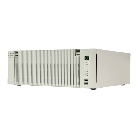
1. GETTING STARTED ● Display and User Input Sections (1) Front view The dimensions do not include rubber feet. 150mm 450mm 400mm Procedure for opening the protective cover [1] Lift up the tab of the protective cover Power switch [2] Pull the cover toward you (*1) [3] Open the cover Digital LED for... -
Page 62: Figure 1-2 Name Of Each Part (Rear View)
1. GETTING STARTED (2) Rear view USB3.0 port (2 ports) DVI-D port B Serial port (COM2) (*5) Serial port (COM1) Main power switch External contacts port (EXT) (*5) AC inlet DisplayPort (*1) Audio port DVI-D port A Upper: LINE IN Lower: LINE OUT Extension slots (From left to right) ACT/LINK lamp... -
Page 63: Figure 1-3 Physical Configuration Inside Equipment
1. GETTING STARTED (3) Physical configuration inside the equipment PS fan Power supply unit Motherboard DVD drive Front fan 2 (installed inside the equipment) Drive bay 2 Front fan 1 Drive bay 1 (installed inside the equipment) Figure 1-3 Physical Configuration Inside Equipment... - Page 64 1. GETTING STARTED Table 1-1 Function of Each Part (1/5) Name Function Power switch (POWER) When you press this switch, the power is turned on. When you press the switch for four seconds or more, the power is turned off and the system goes into standby mode (for emergencies only).
- Page 65 1. GETTING STARTED Table 1-1 Function of Each Part (2/5) Name Function AC inlet Used for connecting a power cord. Power supply A power supply module with a wide-range input voltage (100 to 240 VAC). Main power switch If you press the switch to the 1 position, the power is supplied. If you press the switch to the 0 position, the power is shut down.
- Page 66 1. GETTING STARTED Table 1-1 Function of Each Part (3/5) Name Function You can connect a LAN cable to a LAN port. (See “5.9.1 Connector LAN port specification”.) (1000BASE-T/100BASE-TX/ 10BASE-T) ⚫ Onboard LAN Communication speed lamp ACT/LINK lamp ACT/LINK lamp Lamp Status Lit in green A link is established.
- Page 67 1. GETTING STARTED Table 1-1 Function of Each Part (4/5) Name Function ⚫ Option LAN adaptor (HJ-F7560-20) LAN port (1000BASE-T/100BASE-TX/ 10BASE-T) ACT/LINK lamp Communication speed lamp ACT/LINK lamp Lamp Status Lit in green A link is established. Both the equipment and the remote device are powered up and the connection over the twisted-pair Ethernet cable is stable.
- Page 68 Status indication LEDs LED for Status indication from a user application, refer to the “HF-W7500 ( ) ”.) Model 65/60 RAS FEATURES MANUAL WIN-63-0101 < NOTE > ・ For information about the precautions for USB devices, see “PRECAUTIONS 6. USB DEVICES”.
-
Page 69: Table 1-2 Environment
1. GETTING STARTED 1.6 Installation Environment 1.6.1 Environment CAUTION If you keep at high temperature this equipment, do not touch bare hands. Otherwise you may result burns. When this equipment is used, it must be used in the following environment. Table 1-2 Environment Item Requirement... -
Page 70: Installation Environment
1. GETTING STARTED 1.6.2 Installation WARNING ⚫ The power cord that comes with the equipment is rated at the input voltage of 125 VAC. When using this equipment at over 125 VAC, prepare the power cord fitting input voltage and inspect the safeness of this equipment enough. ⚫... -
Page 71: Figure 1-4 Operation And Service Clearance (Top View)
1. GETTING STARTED Table 1-3 Dimension, Service Clearance, and Installation Clearance Operation and Dimension (mm) Installation clearance (mm) service clearance (mm) Height Width Depth Front Rear Left Right Front Rear Left Right ・When you operate the equipment or do maintenance work, provide sufficient clearance as shown in Figure 1-1. -
Page 72: Figure 1-6 Exterior View (Horizontal Installation On The Desktop)
1. GETTING STARTED (a) Horizontal Installation Place a non-slip mat between the equipment and the desktop to secure the equipment. 150mm 6.0mm Non-slip mat Figure 1-6 Exterior View (Horizontal Installation on the Desktop) (b) Rack mount ・For information about how to attach and remove rack-mounting metal fittings, see “6.3.8 Attaching and removing rack-mounting metal fittings (option)”. - Page 73 1. GETTING STARTED • When mounting the equipment inside a rack, fully address the concerns below. For the rack mounting metal fittings, see Subsection 1.6.2 Installation (b), “Rack mount.” • Elevated Operating Ambient: If installed in a closed or multi-unit rack assembly, the operating ambient temperature of the rack environment may be greater than room ambient.
-
Page 74: Figure 1-8 Exterior View (Vertical Installation)
1. GETTING STARTED (c) Vertical Installation ・When you install the equipment vertically, the status display lamps must come at the upper side and make sure the equipment is placed so it does not fall. ・When you mount the equipment vertically, prepare a mounting metal fitting as shown in the figure below and use it to secure the equipment. -
Page 75: Hardware Connection
1. GETTING STARTED 1.7 Hardware connection WARNING ⚫ Do not apply a heavy load on the cables connected to equipment while the equipment is operating. Use of the equipment with a load applied to the cables might cause smoke or fire. NOTICE ⚫... -
Page 76: Power Cord
1. GETTING STARTED Connect hardware based on the connection example shown in the figure below. Connect the display, keyboard, and mouse to this equipment and then insert the plug of the power cord into an outlet. (the equipment connection side) Power cord for this equipment Cable tie mount (tie anchor) (for USB cables) - Page 77 1. GETTING STARTED ⚫ Connecting to an outlet Fully and securely insert the plug of the power cord of this equipment into an outlet with a grounding pole that is properly grounded. (*1) Make sure you use a power cord with a 2-pole plug with a grounding pole.
- Page 78 1. GETTING STARTED 1.8 Power cord CAUTION When procuring an AC power cord, make sure that the cord has proper rating and meets local safety requirements whatever applicable. Otherwise, an electric shock or machine failure may result. The power cord that comes with the equipment is rated at the input voltage of 125VAC. When using this equipment at over 125VAC, prepare the power cord fitting input voltage and inspect the safeness of this equipment enough.
-
Page 79: Table 1-4 Power Cord And Plug Identification
1. GETTING STARTED Table 1-4 Power Cord and Plug Identification Reference Input rating Plug configuration Cord and connector standards 100V - 120V 1 ANSI C73.11 2 NEMA 5-15P 3 IEC 83 North America 125V 1 ANSI C73.11 2 NEMA 5-15P a=7±0.05 mm 3 IEC C13 b=7±0.05 mm... - Page 80 This Page Intentionally Left Blank...
-
Page 81: Chapter 2 Operation
2. OPERATION CHAPTER 2 OPERATION 2.1 Before Turning On the Power WARNING If any of the air intake and exhaust holes of the equipment is blocked, the temperature inside the equipment may rise and that may cause a fire or failure of the equipment. -
Page 82: Starting The Equipment
2. OPERATION 2.2 Starting the Equipment Follow the procedure below to start the equipment: 1. Connect the plug of the power cord to the outlet. 2. Turn on the power to the display. 3. Turn on the main power switch on the rear of the equipment. The standby lamp (STBY) will be turned on. -
Page 83: Shutting Down The Equipment
2. OPERATION 2.3 Shutting Down the Equipment When you shut down the equipment, first confirm that no other users are using the equipment and no background programs are running. Then follow the procedure below: ・Stop application programs. ・Shut down the OS. The specific procedure for stopping an application program differs depending on each application. -
Page 84: Power Shutdown
2. OPERATION 2.4 Power Shutdown Confirm that the equipment is shut down. (See “2.3 Shutting Down the Equipment”.) Turn off the main power switch. When the main power is turned off, the standby lamp (STBY) is turned off. 2.5 Emergency Shutdown WARNING In case of smoke, a burning smell, or the like, unplug the power cord from the outlet, and contact your dealer or maintenance personnel. -
Page 85: Dvd Drive
2. OPERATION 2.6 DVD drive NOTICE ● If you insert or access an Optical disc, the system load may increase and running applications may be affected. Do not insert or access an optical disc during online operation (system operation). ● When you finish accessing an Optical disc, eject the disc from the DVD drive. If you leave the disc in the DVD drive, failure may result. -
Page 86: Inserting An Optical Disc
2. OPERATION 2.6.1 Inserting an Optical disc 1. Press the eject button gently to open the disc tray. 2. Set the Optical disc on the disc tray with the label side facing up. 3. Push the disc tray to load the disc into the DVD drive. Front View When the Disc Tray Is Open Eject button Disc tray... -
Page 87: Controlling The Power Using The Lan
2. OPERATION 2.7 Controlling the Power Using the LAN The power for this equipment can be turned on from a remote device by way of the LAN. This section explains WOL (Wake ON LAN), which is used for turning on the power for the equipment through the LAN. - Page 88 2. OPERATION 2. Use DESKTOP-xxxxxxx to select the WOL function of either LAN1 or LAN2 to be enabled. For the xxxxxxx part, the character string to be displayed might differ depending on the equipment. Select whether to enable the WOL function of LAN1 or LAN2.
-
Page 89: Turning On The Power Using The Lan
2. OPERATION 2.7.2 Turning on the power using the LAN 1. Perform steps 1 through 3 described in “2.7.1 Enabling the WOL (Wake ON LAN) function” to enable the WOL function. 2. Use the shutdown processing to turn off the power. The standby lamp (STBY) is turned on. - Page 90 2. OPERATION < About the Magic Packet™ frame > In a Magic Packet™ frame, the SOURCE ADDRESS, DESTINATION ADDRESS (the MAC address of the receiver or the MULTICAST ADDRESS including the BROADCAST ADDRESS), CRC, and the like must meet the basic requirements of the LAN in use. The data in a Magic Packet™...
-
Page 91: Setting Up The Lan Interface
2. OPERATION 2.8 Setting Up the LAN Interface This equipment has two built-in 1000BASE-T/100BASE-TX/10BASE-T LAN ports. For information about the location of the LAN port connector (1000BASE-T/100BASE-TX /10BASE-T), see “1.5 Name and Function of Each Part”. < NOTE > ・ For information about the precautions for the network, see “PRECAUTIONS 2. NETWORK”. - Page 92 2. OPERATION ● Setting the network transfer speed (The display image assumes Windows® 10 but it is similar under other OS.) 1. Log on to the computer using an administrator's account. 2. Right-click Start. Then click Device Manager. The Device Manager window appears. 3.
- Page 93 2. OPERATION 4. Click ACPI x64-based PC > Microsoft ACPI-Compliant System > PCI Express Root Complex. 2-13...
- Page 94 2. OPERATION 5. See the following and double-click the network adapter you want to configure and open Network Connection Properties window. [When you configure the built-in LAN (LAN1)] Click Intel(R) PCI Express Root Port #20 – A343. Then double-click the network adapter under it (in the example in the figure below, Intel(R) I210 Gigabit Network Connection).
- Page 95 2. OPERATION 6. Click the Advanced tab. Select Speed & Duplex. 7. Select the transfer speed and the transfer mode you want to choose from the Value list. ・Auto Negotiation: auto-negotiation setting ・10 Mbps Half Duplex: 10 Mbps/Half-duplex setting ・10 Mbps Full Duplex: 10 Mbps/Full-duplex setting ・100 Mbps Half Duplex: 100 Mbps/Half-duplex setting ・100 Mbps Full Duplex: 100 Mbps/Full-duplex setting ・1.0 Gbps Full Duplex: 1.0 Gbps/Full-duplex setting...
- Page 96 2. OPERATION If you do not have to configure the transfer speed and the transfer mode, select Auto Negotiation at the top of the list to choose the auto-negotiation setting. 8. Click OK. 9. Close the Device Manager window. < NOTE > ・...
- Page 97 2. OPERATION ⚫ Action to take if the link is unstable at 1.0 Gbps Depending on the type of the connected hub, the link may not be stable at 1.0 Gbps. If you want to use the network at 1.0 Gbps, verify the connection with the hub in advance. If the link is unstable at 1.0 Gbps, it is made stable by taking the following action.
- Page 98 2. OPERATION ⚫ Precautions for mounting and using multiple LAN adapters If multiple LAN adapters are mounted and there are frequent interrupt requests from either of the adapters or the amount of processed data is too large, the performance of the adapters may not be as high as expected.
- Page 99 2. OPERATION ・Flow Control This enables adapters to generate or respond to flow control frames, which help regulate network traffic. The default setting of the flow control is different depending on the OS and the type of LAN adapter in use. You must configure the flow control setting according to the network you are using.
- Page 100 2. OPERATION ・Interrupt Moderation Rate This sets the rate at which the controller moderates or delays the generation of interrupts. ・Receive Buffers This sets the number of Receive Buffers used by the driver when copying data to protocol memory. 2-20...
- Page 101 2. OPERATION ・Transmit Buffers This sets the number of Transmit Buffers, data segments used by the adapter when recording transmission packets in system memory. 2-21...
- Page 102 2. OPERATION ⚫ Notes about the case when link down is recorded in the log during OS startup. While Windows® is starting, the following warnings may be displayed in the event log. These warnings are recorded by the initialization process of the LAN driver at the startup of Windows®...
-
Page 103: Setting Up The Screen
2. OPERATION 2.9 Setting Up the Screen For screen settings, you can configure resolution (the number of dots that constitutes the screen), refresh rate (the number of screen refreshes per second), and the single- display and multiple-display settings. (The display image assumes Windows® 10 but it is similar under other OS.) <... - Page 104 2. OPERATION 2. You can change the resolution (the number of dots that make up the screen) on the display screen. 3. To change the refresh rate (the number of times the screen is updated per second), click Advanced display settings on the above screen to display the Display adapter properties for Display 1 on the screen displayed below.
- Page 105 2. OPERATION 4. Click the Monitor tab. Select an appropriate value from the Screen refresh rate list in Monitor Settings. 5. Click OK. 6. If the following is displayed, click Keep changes. < NOTE > ・ When you configure the resolution, color depth, and refresh rate, you must choose from the options described in “5.1 Equipment Specification (6) Supported resolutions”.
- Page 106 2. OPERATION (2) Configuring screen settings for two (multiple) displays This equipment supports multiple display output. If you connect two displays, the two displays can be used simultaneously. The following shows how to set up the multiple display output. 1. As described in "(1) Configuring screen settings for a single display", start Display settings.
- Page 107 2. OPERATION < NOTE > ・ The multi-stream function (daisy chain) of DisplayPort is not supported. ・ Types of Multiple displays settings. (Some settings are not displayed depending on the number of displays connected.) Setting items Description ・Extend desktop to this display The main display and other additional displays ・Extend these displays are displayed as the displays.
- Page 108 This Page Intentionally Left Blank...
-
Page 109: Chapter 3 Setup
3. SETUP CHAPTER 3 SETUP 3.1 Setup Procedure when you turn on the power for the first time 3.1.1 Setting up Windows® 10 This section describes the procedure for setting up the preinstalled Windows® 10. • Set basic items of Windows® 10. •... - Page 110 3. SETUP ● Windows® 10 setup procedure Perform the following procedure to set up Windows® 10. 1. Turn on the power to this equipment. Windows starts running and setup is prepared. • This might take several minutes. Please wait until it completes. •...
- Page 111 3. SETUP 10. The Create a really memorable password window will appear. • Enter a password in the Password field, and then click the Next button. • The Confirm your password window will appear. Re-enter the password in the Confirm password field, and then click the Next button. <...
- Page 112 3. SETUP 16. The Partition Size Setting window opens. • The minimum (default) and maximum (MAX) range capacities are displayed. Set the capacity you want to create and click the OK button. The minimum value of the range that can be created is the capacity of the factory default setting (default).
- Page 113 3. SETUP 17. The confirmation window for partition capacity setting displayed. Click the OK button if the displayed partition capacity is OK. 18. When the partition capacity setting is successful, the following message is displayed. Click the OK button. Exit the dialog. Setup will then continue, and the following messages will be displayed: “Windows System Assessment Tool”...
-
Page 114: Setting Up Windows Server® 2019
3. SETUP 3.1.2 Setting up Windows Server® 2019 This section describes the procedure for setting up the preinstalled Windows Server® 2019. • Set basic items of Windows Server® 2019. • The RAS function is automatically set up. • This setup procedure takes about 30 minutes. ●... - Page 115 3. SETUP ● Windows Server® 2019 setup procedure Perform the following procedure to set up Windows Server® 2019. 1. Turn on the power to this equipment. Windows starts running and setup is prepared. • This might take several minutes. Please wait until it completes. •...
- Page 116 3. SETUP 6. The Partition Size Setting window opens. • The minimum (default) and maximum (MAX) range capacities are displayed. Set the capacity you want to create and click the OK button. The minimum value of the range that can be created is the capacity of the factory default setting (default).
- Page 117 3. SETUP 7. The confirmation window for partition capacity setting displayed. Click the OK button if the displayed partition capacity is OK. 8. When the partition capacity setting is successful, the following message is displayed. Click the OK button. Exit the dialog. Setup will then continue, and the following messages will be displayed: “Windows System Assessment Tool”...
-
Page 118: Configuring Basic Settings After Os Setup
3. SETUP 3.2 Configuring Basic Settings after OS Setup 3.2.1 Basic Settings for Windows® 10 and Windows Server® 2019 This section describes the basic settings procedure of the preinstalled Windows® 10 and Windows Server® 2019. Perform this procedure as needed after the setup of OS according to “3.1 Setup Procedure Required after the First Power-on”. - Page 119 3. SETUP 3.2.1.2 Setting Up Automatic Updates Windows® 10 and Windows Server® 2019 settings allow update programs delivered from Windows Update to be applied automatically. The system and application update programs are regularly checked and are automatically downloaded and installed. Perform the following procedure to set auto-update.
- Page 120 3. SETUP The automatic update settings in Windows® 10 and Windows Server® 2019 include the following items. (1) Changing the active hours Downloads and installation will be performed automatically, but system will not restart during active hours. Rather, restarts will be scheduled outside of active hours. Configure this setting according the needs of the customer environment.
- Page 121 3. SETUP [Enabling manual update of Windows Update] If you do not want auto download and installation of update programs, you can set Windows Update to manual update by using the local group policy editor (gpedit.msc). The following describes the procedure to set Windows Update to manual update. 1.
- Page 122 This Page Intentionally Left Blank...
-
Page 123: Chapter 4 Precautions While The Os Is Running
4. PRECAUTIONS WHILE THE OS IS RUNNING CHAPTER 4 PRECAUTIONS WHILE THE OS IS RUNNING 4.1 Event Log Entries during Setup This equipment may record the following events in the event log during the OS setup, but those events do not affect the operation of the system. Table 4-1 Error / Warning Eventlog (During the OS setup) Source Event ID... -
Page 124: Event Log Entries While The Os Is Running
4. PRECAUTIONS WHILE THE OS IS RUNNING 4.2 Event Log Entries While the OS is Running This equipment may record the following events in the event log while the OS is running, but those events do not affect the operation of the system. Table 4-2 Error / Warning Eventlog (While Windows®... - Page 125 4. PRECAUTIONS WHILE THE OS IS RUNNING This equipment may record the following events in the event log while the OS is running Table 4-3 Error / Warning Eventlog (While Windows® 10 and Windows Server® 2019 running) (2/2) Source Event ID Type DistributedCOM 10016...
-
Page 126: Scheduled Functions By Default
4. PRECAUTIONS WHILE THE OS IS RUNNING 4.3 Scheduled Functions by Default In Windows®, various functions are scheduled by default and executed periodically in the background. Among those functions, Windows Defender (anti-spyware feature) and the disk defragmenter (or optimize drives) may increase the system load significantly when they run and may affect the operation of the applications for business use. - Page 127 4. PRECAUTIONS WHILE THE OS IS RUNNING 4. The Optimize Drives window appears. ・ Under Scheduled optimization, click Turn on. 5. The Optimization schedule window appears. Select the Run on a schedule (recommended) check box. 6. As required, configure the frequency of defragmentation. The initial schedule of defragmentation is as follows.
- Page 128 4. PRECAUTIONS WHILE THE OS IS RUNNING 8. The Select the drives you want to optimize on a regular schedule window appears. As required, select the drives you want to defragment ・ Click OK. 9. The Optimization schedule window appears. Click OK. 10.
- Page 129 4. PRECAUTIONS WHILE THE OS IS RUNNING (b) Run the drive optimization manually. 1. Execute steps 1 though 3 in ” (a) Turn on the drive optimization schedule.” 2. The Optimize Drives window appears. ・ Under Status, select the drive you want to defragment, and click Optimize. ・When the disk optimization process is complete, the date and time of the optimization is displayed in the Last Run column.
-
Page 130: Security Enhancement Function
4. PRECAUTIONS WHILE THE OS IS RUNNING 4.4 Security Enhancement Function In Windows® 10 and Windows Server® 2019, a spyware preventive function Windows Defender has been enabled. The Windows Defender also includes a virus preventive function. Windows Defender also has antivirus functions that might adversely impact application performance. -
Page 131: Product Activation In Windows® 10
4. PRECAUTIONS WHILE THE OS IS RUNNING 4.6 Product Activation in Windows® 10 In Windows® 10, product activation is carried out automatically when you connect the Internet connection. If you don't carry out the Product Activation in the environment unconnected to the Internet, "Connect to the Internet to activate Windows"... -
Page 132: Display Of Device Manager
4. PRECAUTIONS WHILE THE OS IS RUNNING 4.8 Display of Device Manager The PCI Simple Communications Controller (PCI bus 0, device 22, function 0) of this device is Intel® Management Engine (Intel® ME). This device does not use the Intel® ME function, so the driver is not installed. -
Page 133: Chapter 5 Specifications
5. SPECIFICATION CHAPTER 5 SPECIFICATIONS 5.1 Equipment Specifications (1) Common specifications Table 5-1 Common specifications list Item Specifications See “(2) Individual specifications”. Model See “(2) Individual specifications”. Processor Main memory 16GB/32GB/64GB Display resolution See “(6) Supported resolutions”. and color depth DVD drive (*1) Built-in file See “(2) Individual specifications”. - Page 134 5. SPECIFICATION (*1) The DVD drive in this equipment supports the following types of media. Read supported : CD-ROM, DVD-ROM, DVD-RW, DVD-R Depending on its condition, an Optical disc might be unreadable. In such a case, use another Optical disc. We do not support writing to media because writing might be impossible depending on the quality of the media.
-
Page 135: Table 5-2 Individual Specifications List
5. SPECIFICATION (2) Individual specifications Table 5-2 Individual specifications list Specifications Item HF-W7500 model 65 HF-W7500 model 60 Model(*1) D model : HJ-7565-xxyD D model : HJ-7560-xxyD Processor Intel® Xeon® E-2226GE Intel® Xeon® E-2124G SATA HDD 2TB Drive bay 1... -
Page 136: Table 5-3 Os Type List
5. SPECIFICATION (3) Pre-installed OS model Table 5-3 OS type list OS type Pre-installed OS Microsoft® Windows® 10 IoT Enterprise 2019 LTSC (64bit) (Embedded licensing version) Microsoft® Windows Server® IoT 2019 Standard (64bit) (Embedded licensing version) NO OS (4) Accessories Table 5-4 Accessories list Item Specifications... -
Page 137: Table 5-6 Supported Resolutions List
(*1) It has been confirmed that all refresh rate settings indicated in the table actually work in the test environment provided by Hitachi. Note that supported resolutions and refresh rates vary depending on the display. Therefore, some settings might be unavailable for a specific display. -
Page 138: Table 5-9 Maximum Current Specifications
5. SPECIFICATION (9) Maximum current specifications (USB port, Extension board, DisplayPort) The following table shows the maximum total current consumption for the USB ports, extension slots (PCI Express / PCI) and DisplayPort. Table 5-9 Maximum current specifications Maximum total current consumption for USB port 8 ports/ DC Output Extension board 7 slots/... -
Page 139: Memory Space
5. SPECIFICATION 5.2 Memory Space 0000 Main Memory A_0000 Legacy Video Area B_FFFF (SMM Memory)(128K) Space available for real mode. C_0000 Video BIOS(Max 64K) (*1) C_FFFF D_0000 Option ROM(64K) (*2) D_FFFF E_0000 Extended System BIOS/System F_FFFF BIOS(128K) (1MB)10_0000 Main Memory TSEG_BASE TSEG (TSEG_SIZE) (Max) D000_0000 PCI Memory E000_0000... -
Page 140: I/O Space
5. SPECIFICATION (*1) The video BIOS is not supported, so the relevant area is free (reserved). (*2) The extended BIOS space is a narrow space between D0000 and DFFFF and may already be in use by other devices. In addition, the size of the BIOS of standard built-in adapters may change in future versions. -
Page 141: Interrupts List
5. SPECIFICATION 5.4 Interrupts list Table 5-12 Interrupts list Interrupt pin Description Cascade (from 8259 #1) IRQ0 IRQ1 Not used Timer IRQ2 IRQ3 Serial port 2 (COM2) Serial port 1 (COM1) IRQ4 IRQ5 Not used Not used IRQ6 IRQ7 Not used Real-time clock IRQ8 IRQ9... -
Page 142: Serial Port Settings
5. SPECIFICATION Table 5-13 Interrupts list (IRQ assignment when the APIC is disabled) Interrupt pin Description IRQ0 Timer IRQ1 Not used IRQ2 Cascade IRQ3 Serial port 2 (COM2): B IRQ4 Serial port 1 (COM1): A IRQ5 Not used IRQ6 Not used IRQ7 Not used IRQ8... -
Page 143: Bios Setup
5. SPECIFICATION 5.6 BIOS Setup The BIOS stores the system configuration information in the SPI-ROM. When the system configuration is modified, it may be necessary to change the BIOS settings. < NOTE > When the equipment is shipped, the BIOS is configured in accordance with the system configuration. -
Page 144: Table 5-16 Bios Setup Menu List
5. SPECIFICATION (4) Details of the setup menu The following tables show the details of the items you can set up in each menu. Table 5-16 BIOS Setup menu list (1/3) Setting item Default value Note menu Main System Date When you set the system up for the first time, be sure to System Time... - Page 145 5. SPECIFICATION Table 5-16 BIOS Setup menu list (2/3) Setting item Default value Note menu Advanced I/O Device Serial port A Enabled Do not change this setting. Configuration Base I/O Address 3F8h Interrupt IRQ4 Serial port B Enabled Base I/O Address 2F8h Interrupt IRQ3...
- Page 146 5. SPECIFICATION Table 5-16 BIOS Setup menu list ( (3/3) Setting item Default value Note menu Power After AC Power On Auto Specifies the action when the power to the equipment is turned on. Power On : When the power is turned on, the OS is started automatically.
- Page 147 5. SPECIFICATION (5) Restoring the default settings When you want to restore all items in the setup menu back to the default settings, follow the procedure below: 1. Start the setup menu. (See “(1) Starting the setup menu”.) 2. Open Exit in the top menu. Move the cursor to Load Setup Defaults and press Enter. The message “Load default configuration now?”...
-
Page 148: Boot Menu
5. SPECIFICATION 5.7 Boot menu When starting up the system, you can boot from a device different from the boot device priority in the BIOS setup menu, and start the BIOS setup menu and Internal Shell. < NOTE > When the equipment is shipped, the Boot menu is configured in accordance with the system configuration. -
Page 149: Hardware System Clock
5. SPECIFICATION 5.8 Hardware System Clock This equipment has a hardware system clock that uses an RTC (real-time clock) IC. The clock has a built-in calendar and continues to work using a backup battery even when the system power is off. Table 5-19 Hardware System Clock Specification Item Specifications... -
Page 150: Interface Specifications
5. SPECIFICATION 5.9 Interface Specifications 5.9.1 Connector specifications The following shows the specifications of the interfaces from this equipment to external devices. For information about the location of the ports, see “1.5 Name and Function of Each Part”. (1) Motherboard (Standard) ●... - Page 151 5. SPECIFICATION ● Serial port (male connector, inch screws) (COM1, COM2 (optional) ) Pin No. Signal name Pin No. Signal name ● LAN port (RJ-45 modular port 8 pins) Pin No. Signal name TRD0+ TRD0- TRD1+ TRD2+ TRD2- TRD1- TRD3+ TRD3- For network connection, use a cable specified as follows.
- Page 152 5. SPECIFICATION ● Video port (DVI-D 24 pins, inch screws) Pin No. Signal name Pin No. Signal name Pin No. Signal name TX2M TX1M TX0M TX2P TX1P TX0P SGND SGND SGND NC(TX4M) NC(TX3M) NC(TX5M) NC(TX4P) NC(TX3P) NC(TX5P) DDCCLK2 P5DFP SGND DDCDAT2 PGND TXCP...
- Page 153 5. SPECIFICATION ● Audio port: LIN and LOUT (3.5φ stereo audio port) LOUT Pin No. Signal name Pin No. Signal name AGND AGND LIN_L LOUT_L LIN_R LOUT_R Mold Plug Audio cable < NOTE > The diameter of the mold of the cable must be 10 mm or less. If the diameter of the mold is larger than 10 mm, when you try to connect cables to both LINE IN and LINE OUT, the two molds get in the way of each other and you cannot insert the connectors.
- Page 154 5. SPECIFICATION (2) RAS external control interface (optional) NOTE: Serial port and External control I/O port ● External control I/O port (male connector, inch screws) Pin No. Signal name Pin No. Signal name MCALL_1 MCALL_2 GENDO0_1 GENDO0_2 GENDO1_1 GENDO1_2 WDTTO_1 WDTTO_2 PSDOWN_1 PSDOWN_2...
-
Page 155: External Control Specifications
5. SPECIFICATION 5.9.2 External control specifications (1) External control I/O port (EXT) specifications Table 5-20 External control I/O port specifications Item Sub-item Specification External Usage RMTRESET, RMTSHTDN (GENDI), GENDI0, control GENDI1, and GENDI2 (RMTPWRON) (*1) (*2) (*3) input Electrical Interface Non-voltage transistor contact interface Contact current... -
Page 156: Table 5-21 List Of External Control I/O Signals
5. SPECIFICATION (2) List of external control I/O signals Table 5-21 List of external control I/O signals (1/2) Connection diagram HJ-F7560-17 HJ-F7560-18 Signal name Meaning B contact A contact CPU side Terminal User side specifications specifications PSDOWN_1 40 VDC 0.1A Activated when the OS is When the power is When the power is... - Page 157 5. SPECIFICATION Table 5-21 List of external control I/O signals (2/2) Connection diagram HJ-F7560-17 HJ-F7560-18 Signal name Meaning B contact A contact CPU side Terminal User side specifications specifications RMTSHTDN_1 This is a shutdown request 5V(VCC) (GENDI_1) signal or a general purpose input signal.
- Page 158 5. SPECIFICATION (3) Recommended EXT cable specifications 1. For connection, the following cable is required. Model: HJ-7805-C1-XX, where the XX part shows the length. (*1) D-sub 25-pins M4 solderless female terminal connector Shielded grounding (*2) (*1) The maximum cable length is 30 m. (*2) To connect a cable shield, beside the cable, you must provide a shielded grounding bar dedicated for a shielded wire connection.
-
Page 159: External Interface Cable Length Specifications
5. SPECIFICATION 5.9.3 External interface cable length specifications The recommended maximum cable length for each interface of this equipment is as follows. Table 5-22 External interface cable length specifications Connector name Cable length (m) Remarks DVI-D port DisplayPort UTP Category 5e or better LAN port For information about the cable External control I/O port (Optional) - Page 160 This Page Intentionally Left Blank...
-
Page 161: Chapter 6 Checkup And Maintenance
6. CHECKUP AND MAINTENANCE CHAPTER 6 CHECKUP AND MAINTENANCE 6.1 Daily Checkup WARNING Make sure to install a dust filter to equipment. If you do not, dusts enter into the equipment and the short circuit fire may occur as a result. CAUTION Before you clean or replace the dust filter or the case fan of this equipment, make sure you shut down the OS, turn off the main power of the equipment,... - Page 162 6. CHECKUP AND MAINTENANCE (1) Cleaning a dust filter NOTICE If you wash a dust filter, dry it completely before re-attaching it to the equipment. If you use the equipment while its dust filter is not completely dry, the equipment may fail.
- Page 163 ● Do not spray detergent directly on to the keyboard or spill liquid detergent on it. ● Do not wipe the keyboard with a wet cloth. If you do, the equipment may fail. HITACHI ● When you use detergent, spray a minimum amount of detergent on a cloth.
-
Page 164: Periodic Checkup
6. CHECKUP AND MAINTENANCE 6.2 Periodic Checkup The table below shows how to check up the Equipment periodically. A qualified maintenance personnel must conduct this periodical checkout. Include the checkout time in the system operation schedule. Table 6-1 Periodic Checkup Checkup item Frequency Note... -
Page 165: Installing And Removing Components
6. CHECKUP AND MAINTENANCE 6.3 Installing and Removing Components 6.3.1 Types and locations of installed components The figure below shows the types and locations of the components installed in this equipment. Front fan Dust filter Fan duct DVD drive Main memory slot (from right to left, A1 and A2 and B1 and B2) -
Page 166: Before Installing Or Removing Components
6. CHECKUP AND MAINTENANCE 6.3.2 Before installing or removing components When you install or removing components, confirm and keep strictly the following instructions. WARNING ● Do not open the equipment cover if you are not a maintenance personnel. In addition, do not install or replace the hardware. ●... -
Page 167: Installing And Removing The Cover Of The Equipment
6. CHECKUP AND MAINTENANCE 6.3.3 Installing and removing the cover of the equipment CAUTION When you install the cover of the equipment, do not put your fingers inside the cover. If you do, your fingers may get caught and injured. Before starting to work, see “6.3.2 Before installing or removing components”. -
Page 168: Installing And Removing An Extension Board
6. CHECKUP AND MAINTENANCE 6.3.4 Installing and removing an extension board WARNING Before you install or remove an extension board, make sure you shut down the OS, unplug the power cord from the outlet, and wait for at least one minute. If you install or remove an extension board without shutting down the power, an electric shock or a fire may result. -
Page 169: Table 6-2 Extension Boards List
The board sizes (length × height) in the PCI Express / PCI specifications are as follows (the height includes the connector): ● PCI Express specification ・Short size: 167.65 × 111.15 (mm) ● PCI specification ・Short size: 174.63 × 106.68 (mm) - Page 170 6. CHECKUP AND MAINTENANCE (3) Removing an extension board or a slot cover [1] Follow the instructions in “6.3.3 Installing and removing the cover of the equipment” to remove the cover of the equipment. [2] Remove the screw of the slot where you want to install an extension board or a slot, and remove an extension board or a slot cover.
-
Page 171: Figure 6-3 Installing An Extension Board
6. CHECKUP AND MAINTENANCE (4) Installing an extension board or a slot cover [1] See “(3) Removing an extension board or a slot cover”, and remove the cover of the equipment. [2] If the PCI connector or the PCI Express connector has a cover, remove the cover. When installing a slot cover, attach the cover to the PCI connector or the PCI Express connector. -
Page 172: Installing And Removing A Main Memory
6. CHECKUP AND MAINTENANCE 6.3.5 Installing and removing a main memory WARNING Before you install or remove main memory, make sure you shut down the OS, unplug the power cord from the outlet, and wait for at least one minute. If you install or remove main memory without shutting down the power, an electric shock or a fire may result. -
Page 173: Figure 6-4 Removing The Sata Cables
6. CHECKUP AND MAINTENANCE (2) Installing a main memory NOTICE ⚫ The orientation of a main memory module on a connector is fixed. When you install a main memory module, make sure the orientation is correct. Otherwise, failure of the equipment may result. ⚫... -
Page 174: Figure 6-5 Installing A Main Memory
6. CHECKUP AND MAINTENANCE [3] Make sure the lock on both ends of the connector of the memory slot is open. [4] Insert the main memory into the connector from directly above the connector. When the main memory is inserted, you will hear a click and it is locked. Make sure the lock is completely closed. -
Page 175: Installing And Removing An Hdd
6. CHECKUP AND MAINTENANCE 6.3.6 Installing and removing an HDD CAUTION When you install or remove an HDD, make sure you do not cut your fingers on the protrusions. NOTICE ⚫ Put the HDD on a shock-absorbing material such as an antistatic cushion even for a temporary task. -
Page 176: Figure 6-6 Opening The Front Cover
6. CHECKUP AND MAINTENANCE (2) Removing an HDD [1] Push down on the two claws on the left and right, and open the front cover. [2] Loosen two set screws for the Drive case. [3] Hold two set screws for the Drive case and pull out the case. Push down on the two claws on the left and right, and open the front cover. -
Page 177: Figure 6-8 Removing A Drive Bay 3 Hdd
6. CHECKUP AND MAINTENANCE (3) Removing a Drive bay 3 HDD (Option) [1] Open the front cover referring to [1] of “(2) Removing an HDD”. [2] Loosen two set screws for the Drive case. [3] Hold two set screws for the Drive case and pull out the case. Set screws for the Drive case Figure 6-8 Removing a Drive bay 3 HDD (4) Installing an HDD... -
Page 178: Installing And Removing A Dvd Drive
6. CHECKUP AND MAINTENANCE 6.3.7 Installing and removing a DVD drive CAUTION When you install or remove a DVD drive, make sure you do not cut your fingers on the protrusions. NOTICE Make sure you do not apply too much force to the connector of the DVD drive and the top of the DVD drive. -
Page 179: Figure 6-10 Removing The Screw Fixing The Dvd Drive
6. CHECKUP AND MAINTENANCE [6] Remove the screw fixing the equipment and the DVD drive. (Use a Phillips screwdriver JIS #2) Figure 6-10 Removing the screw fixing the DVD drive [7] Pull the DVD drive lightly toward the front of the equipment and remove the DVD drive cable from the DVD drive. -
Page 180: Attaching And Removing Rack-Mounting Metal Fittings (Option)
6. CHECKUP AND MAINTENANCE 6.3.8 Attaching and removing rack-mounting metal fittings (option) CAUTION ⚫ Rack-mounting metal fittings are designed to be used for pulling out the equipment toward the front by hooking your fingers on the handles. Do not grip the handles to lift up or carry the equipment. If you do, the equipment may fall and personal injury may result. -
Page 181: Figure 6-12 Attaching Rack-Mounting Metal Fittings
6. CHECKUP AND MAINTENANCE (2) Attaching rack-mounting metal fittings [1] Follow the instructions in “6.3.3 Installing and removing the cover of the equipment” to remove the cover of the equipment. [2] If the rack-mounting metal fittings came with the equipment, use the screws that also came with the equipment to attach the rack-mounting metal fittings. -
Page 182: Attaching And Removing Rubber Feet
6. CHECKUP AND MAINTENANCE 6.3.9 Attaching and removing rubber feet (1) Before attaching and removing rubber feet and cover screws ・Before starting to work, see “6.3.2 Before installing or removing components”. (2) Removing rubber feet [1] Insert the blade of a slotted screwdriver into the center part of a mounted rubber foot. [2] Gradually pry up the cap at the center of the rubber foot by gently pushing the handle of the driver toward the bottom plate of the equipment. -
Page 183: Figure 6-14 Removing Cover Screws
6. CHECKUP AND MAINTENANCE (3) Removing cover screws [1] Remove the four cover screws using a Phillips screwdriver. Cover screw Figure 6-14 Removing cover screws < NOTE > ・ Save the rubber feet, and keep them in place for later use. CAUTION When you install the equipment on the mounting metal fitting for vertical installation, do not use set screws for the cover to secure the equipment. -
Page 184: Replacing A Dust Filter
6. CHECKUP AND MAINTENANCE 6.3.10 Replacing a dust filter WARNING Make sure to install a dust filter to equipment. If you do not, dusts enter into the equipment and the short circuit fire may occur as a result. [1] Follow the instructions in “6.3.6 Installing and removing an HDD (2) Removing an HDD”... -
Page 185: Installing And Removing A Lithium Battery
6. CHECKUP AND MAINTENANCE 6.4 Installing and removing a lithium battery CAUTION ● This equipment uses a lithium battery. When you replace the lithium battery, make sure you replace it with one specified by the Manufacture. Otherwise, an explosion, a fire, a burst battery, heat generation, a liquid spill, or gas generation may result. -
Page 186: Figure 6-16 Removing A Lithium Battery
6. CHECKUP AND MAINTENANCE (2) Removing a lithium battery [1] Follow the instructions in “6.3.3 Installing and removing the cover of the equipment” to remove the cover of the equipment. [2] Remove the lithium battery from the battery holder as shown in the figure below. [3] Remove the lithium battery from the BAT connector on the motherboard. -
Page 187: Enabling The Remote Power On Function
6. CHECKUP AND MAINTENANCE 6.5 Enabling the Remote Power On Function CAUTION Do not directly touch the parts inside the equipment with your hand when you install or remove a jumper socket. Those parts are hot and if you touch them, you may get burned. -
Page 188: Figure 6-17 Removing A Jumper Socket
6. CHECKUP AND MAINTENANCE (2) Removing a jumper socket [1] Follow the instructions in “6.3.3 Installing and removing the cover of the equipment” to remove the cover of the equipment. [2] When removing the jumper socket, follow the instructions in “6.3.4 Installing and removing an extension board”... -
Page 189: Chapter 7 Restoring The Factory-Shipped Condition Usinga Recovery Dvd
7. RESTORING THE FACTORY-SHIPPED CONDITION USING A RECOVERY DVD CHAPTER 7 RESTORING THE FACTORY-SHIPPED CONDITION USING A RECOVERY DVD NOTICE A recovery DVD contains an image file created for the hardware configuration at the factory shipment. If the hardware configuration has changed from the one at the factory, the OS may not start after restoration work. -
Page 190: Preparation
7. RESTORING THE FACTORY-SHIPPED CONDITION USING A RECOVERY DVD 7.2 Preparation Before you start restoration work using recovery DVDs, have the following recovery DVDs ready. Recovery DVD HITACHI HJ-756x-**** Product Recovery DVD for HF-W (The underlined part is the model number of the equipment you purchased.) -
Page 191: Restoring The System Drive Back To The Factory-Shipped Condition
7.3 Restoring the System Drive Back to the Factory-Shipped Condition 7.3.1 Procedure for restoring the system drive back to the factory-shipped condition Follow the procedure below to restore the system drive of an HF-W7500 Model 65/60 back to the factory-shipped condition using a recovery DVD. - Page 192 7. RESTORING THE FACTORY-SHIPPED CONDITION USING A RECOVERY DVD When you click No, the following message box is displayed. Click OK. The recovery DVD is automatically ejected, and then the equipment is automatically shut down. If you want to go back to the confirmation window for the attention message, click Cancel.
- Page 193 ■ The system drive has more than one boot partition. ■ The size of the boot partition is less than the minimum boot partition size defined for this equipment. (For an HF-W7500 Model 65/60, the minimum size is 200 GB.)
- Page 194 7. RESTORING THE FACTORY-SHIPPED CONDITION USING A RECOVERY DVD When you click Cancel, the following message is displayed. Click OK. The recovery DVD is automatically ejected, and then the equipment is automatically shut down. If you want to go back to the selection window for the drive restore option, click Cancel.
- Page 195 7. RESTORING THE FACTORY-SHIPPED CONDITION USING A RECOVERY DVD <When you select Entire drive in the selection window for the drive restore option> 5. If you select Entire drive in the selection window for the drive restore option, the confirmation window for the settings of the drive restoration is displayed. ・If you are OK with the displayed partition size to be restored, click Yes.
- Page 196 7. RESTORING THE FACTORY-SHIPPED CONDITION USING A RECOVERY DVD 7. When you click the Yes button in the confirmation window for the settings of the drive restoration, preparation for restoration to the shipping state starts. The [Status] box displays the following message: “Copying data. Please wait. This might take several minutes.”...
- Page 197 7. RESTORING THE FACTORY-SHIPPED CONDITION USING A RECOVERY DVD 8. When drive restoration processing with the current recovery DVD is complete, the following message is displayed, and the recovery DVD is automatically ejected. Remove the recovery DVD from the DVD drive and insert the next recovery DVD. 9.
- Page 198 DVD is fully completed, “Recovery Complete.” is displayed in the [Status] box. Click Exit, the equipment will be shut down. The system drive of the HF-W7500 Model 65/60 is now successfully restored to the factory condition by using a recovery DVD. After you finish the procedure above, follow the instruction in “CHAPTER 3 SETUP”...
-
Page 199: Errors Generated During A Restoration Process And Their Corrective Actions
7. RESTORING THE FACTORY-SHIPPED CONDITION USING A RECOVERY DVD 7.3.2 Errors generated during a restoration process and their corrective actions When an error occurs during a recovery operation, record the error message and the error code displayed on the window, and then contact the system administrator. Then, take action as shown in the following table. -
Page 200: Chapter 8 Maintenance Operations
8. MAINTENANCE OPERATIONS CHAPTER 8 MAINTENANCE OPERATIONS This chapter describes maintenance operations that use the Reliability, Availability, and Serviceability (RAS) features of this equipment. 8.1 Overview RAS features are designed to achieve highly reliable features of the equipment. The following table shows an overview of the RAS features of this equipment. - Page 201 8. MAINTENANCE OPERATIONS <Monitoring> (1) Hardware status monitoring This function monitors the hardware status of this equipment including the status of the fans and drives as well as the temperature inside the chassis. (2) OS hangs monitoring This function monitors the operational state of the OS by using a dedicated timer implemented on this equipment.
- Page 202 8. MAINTENANCE OPERATIONS This icon is not shown in the notification area of the taskbar by default, but if you click the arrow at the side of the notification area, the icon will appear. Furthermore, you can set this icon to reside in the taskbar notification area.
- Page 203 8. MAINTENANCE OPERATIONS <Control> (11) Automatic shutdown This feature automatically shuts down the equipment when a fan failure, abnormal temperature inside the chassis, or a remote shutdown signal input is detected. Use “(4) RAS setting window” to enable or disable the automatic shutdown feature. (12) Shutdown using library functions You can shut down the equipment from a user application using the RAS library.
- Page 204 This manual explains the features in (13), (16), and (19). For details about other features, refer to “HF-W7500 Model 65/60 RAS FEATURES MANUAL (WIN-63-0101)”. For information in (8) POST messages, see “9.6.1 POST messages”.
-
Page 205: Collecting A Memory Dump
8. MAINTENANCE OPERATIONS 8.2 Collecting a Memory Dump When one of the errors in Table 8-1 occurs, this equipment records the contents of the system memory in a file (memory dump file). Then a blue screen appears and a STOP error code is displayed. - Page 206 8. MAINTENANCE OPERATIONS In order to collect a complete memory dump file, you need a memory dump file of a size comparable to the capacity of the physical memory. In addition, the virtual memory (page file) and memory dump settings must be the ones recommended for this equipment (*3). (*3) 1.
-
Page 207: Memory Dump Confirmation Messages
8. MAINTENANCE OPERATIONS 8.2.1 Memory Dump Confirmation Messages If the capacity of the physical memory exceeds the capacity of the memory dump file or the virtual memory due to, for example, newly added physical memory, or if a complete memory dump cannot be collected because the memory dump setting has changed, this equipment displays the following message and records an event in the event log. -
Page 208: Configuring The Settings Related To A Memory Dump
8. MAINTENANCE OPERATIONS 8.2.2 Configuring the settings related to a memory dump This subsection describes how to configure the settings related to a memory dump. Use the following procedure when you want change the memory dump setting to the one recommended for this equipment. - Page 209 8. MAINTENANCE OPERATIONS (2) Specifying a memory dump file 1. Click Start > Control Panel > System and Security. Then click System. 2. On the left side of the window, click Advanced system settings. 3. In the Advanced tab page, click Settings under Startup and Recovery. 4.
-
Page 210: Startup Suppression On Serious Failure Detection
If an automatic shutdown is not selected, startup is not suppressed. For information about how to use the RAS setting window, refer to “HF-W7500 Model 65/60 RAS FEATURES MANUAL (WN-63-0101)”. When a remote shutdown signal input is detected, the equipment displays a blue screen and then stops. -
Page 211: Maintenance Operation Commands
8. MAINTENANCE OPERATIONS 8.4 Maintenance Operation Commands This section explains how to use maintenance operation commands. These commands are used when problems occur in the equipment and during preventive maintenance. All these commands are started at the command prompt when they are used. Table 8-3 shows a list of maintenance operation commands. -
Page 212: Log Information Collection Command (Logsave)
8. MAINTENANCE OPERATIONS 8.4.1 Log information collection command (logsave) <Name> logsave - Collecting log information <Syntax> logsave [-e file name][Directory] <Feature> The logsave command saves the data used for preventive maintenance and post-failure analysis of problems. The data is compressed and recorded as one file (File name: logsave.zip). -
Page 213: Table 8-5 Error Messages Of The Logsave Command
・Start the command prompt with administrator privileges and run the command. ・The log information can also be collected by using a program in the start menu For details, refer to “HF-W7500 Model 65/60 RAS FEATURES MANUAL (WIN- 63-0101)”. ・Confirm the existence of the collected files by Double-clicking on the saved zip file. -
Page 214: Memory Dump File Copy Command (Mdump)
8. MAINTENANCE OPERATIONS 8.4.2 Memory dump file copy command (mdump) <Name> mdump - Copying a memory dump file <Syntax> mdump [-n | -e file name] <Copy (Decompress) destination path name> <Feature> The mdump command compresses a memory dump file collected by Microsoft® Windows® when the equipment stops unexpectedly. -
Page 215: Table 8-6 Error Messages Of The Mdump Command
・Do not run the mdump command immediately after the OS start after the blue screen is displayed. If you do, the Compressed Folders Error occurs. For details, refer to “HF-W7500 Model 65/60 RAS FEATURES MANUAL (WIN-63-0101)”. ・Confirm the existence of the memory dump file by Double-clicking on the saved zip file. -
Page 216: Disk Area Allocation Command For Saving A Memory Dump (Createdmp)
8. MAINTENANCE OPERATIONS 8.4.3 Disk area allocation command for saving a memory dump (createdmp) <Name> createdmp - Reserving a disk area for a memory dump file <Syntax> createdmp <Feature> The createdmp command creates a vacant memory dump file beforehand and reserves the disk area for a memory dump in order to prevent the situation where collecting a memory dump fails because the disk capacity is insufficient. -
Page 217: Table 8-7 Error Messages Of The Createdmp Command
8. MAINTENANCE OPERATIONS <Diagnosis> When this command finishes normally, the command exits without output in the command prompt window. When this command is terminated with an error, the following error message is displayed. Table 8-7 Error Messages of the createdmp Command Error message Meaning Error: In the current settings, memory dump file... -
Page 218: Ras Information Display Command (Getrasinfo)
8. MAINTENANCE OPERATIONS 8.4.4 RAS information display command (getrasinfo) <Name> getrasinfo - Displays the status of the equipment such as the status of the fan and the temperature inside the chassis as well as the configuration information of the RAS software <Syntax>... - Page 219 8. MAINTENANCE OPERATIONS <Display output> The following is an example of display output when the getrasinfo command is executed without options. <<getrasinfo result>> Date: 2021/10/30 17:28:30 Header Model Name: HJ-756x [Hardware Status] [Fan condition] PS fan status: Normal Front fan1 status: Normal Front fan2 status: Normal...
- Page 220 8. MAINTENANCE OPERATIONS [RAS Setting] [Automatic shutdown setting] Fan: Temperature: Remote shutdown: [Watchdog timer setting] Retrigger type: Automatic Timeout: 60 sec Interval: 20 sec [Drive failure prediction setting] Function is available: Enable [Drive used hours monitoring setting] Function is available: Enable Drive bay1: Enable...
- Page 221 8. MAINTENANCE OPERATIONS <Explanation of the display output> ■ Header: This section shows the date and time when the getrasinfo command is executed and the model name. The following is the format of the header. << getrasinfo result >> Date : YYYY / MM / DD hh : mm : ss Model Name : HJ - 756x YYYY: Year, MM: Month, DD: Day, hh: hour (24-hour clock), mm: minute, ss: second...
- Page 222 8. MAINTENANCE OPERATIONS ・ [RAID condition] section: Shows the RAID status. The following table shows the list of items in this subsection and their respective descriptions. Output item Description Arrayxx Shows the number of the RAID array. Status: yy(zz ww, Media Shows the RAID status Error) Optimal:Normal status...
- Page 223 8. MAINTENANCE OPERATIONS ・ [Memory condition] section: Shows the status of the main memory. The following table shows the list of items in this subsection and their respective descriptions. Output item Description DIMM xx status:yy Shows the memory slot name. A1:DIMM A1 A2:DIMM A2 B1:DIMM B1...
- Page 224 8. MAINTENANCE OPERATIONS ・ [Watchdog timer setting] section: Shows the watchdog timer setting. The following table shows the list of items in this subsection and their respective descriptions. Output item Description Retrigger type:xx Shows the retrigger type. Automatic: Automatically retriggered. Application: Retriggered by an application.
- Page 225 8. MAINTENANCE OPERATIONS ・ [Drive used hours monitoring setting] section: Shows the drive power-on (used) hours monitoring setting. The following table shows the list of items in this subsection and their respective descriptions. Output item Description Function is available:xx Shows whether the drive power-on (used) hours monitoring function is enabled or disabled.
- Page 226 8. MAINTENANCE OPERATIONS ・ [Popup setting] section: Shows the pop-up notification setting. The following table shows the list of items in this subsection and their respective descriptions. Output item Description Function is available:xx Shows whether the pop-up notification function is enabled or disabled.
-
Page 227: Table 8-9 Error Messages Of The Getrasinfo Command
8. MAINTENANCE OPERATIONS <Diagnosis> When this command finishes normally, the getrasinfo command returns exit code 0. When this command is terminated with an error, one of the following error messages is displayed and exit code 1 is returned. Table 8-9 Error Messages of the getrasinfo Command Error message Meaning Usage: getrasinfo [/status | /setting] [/e File]... - Page 228 This Page Intentionally Left Blank...
-
Page 229: Chapter 9 Troubleshooting
9. TROUBLE SHOOTING CHAPTER 9 TROUBLESHOOTING This chapter explains the possible causes of common problems and the actions to be taken to address those problems. Select an applicable symptom from the list in “9.1 List of Problems”. Follow the link (“9.2 Countermeasures” through “9.6 Digital LED for Status indication”) and take actions according to the instruction. -
Page 230: Problems That Occur After The Os Startup
9. TROUBLE SHOOTING 9.1.2 Problems that occur after the OS startup The following is a list of problems that occur after the desktop is displayed (after the OS startup). (1) The alarm lamp is lit and the Digital LEDs for Status indication show alphanumeric characters. -
Page 231: Countermeasures
9. TROUBLE SHOOTING 9.2 Countermeasures 9.2.1 Problems that occur before the OS startup (1) The equipment does not start. 1.The standby lamp does not turn on, or the standby lamp turns on but the equipment does not start. <Possible cause> Power is not supplied to the equipment, or there might be a failure in the customer-prepared power supply unit connected to the equipment. - Page 232 9. TROUBLE SHOOTING 4. The screen is blank. <Possible cause> The display has a problem. <Action> 1. Make sure that the power switch of the display is on. 2. Make sure that the plug of the power cord for the display is connected to the outlet. 3.
- Page 233 9. TROUBLE SHOOTING 6. The system stops when the Windows® logo is displayed. <Possible cause> There is an error in hardware, or the OS is corrupted. <Action> 1. Unplug the plug of the power code from the outlet and remove all USB devices except a keyboard and mouse as well as all extension boards.
- Page 234 9. TROUBLE SHOOTING (3) The BIOS setup menu cannot be opened. <Possible cause> Keyboard input is not accepted. <Action> 1. Disconnect the keyboard cable and securely reconnect it to ensure stable connection. 2. Connect the keyboard cable to another port. 3.
-
Page 235: Problems That Occur After The Os Startup
9. TROUBLE SHOOTING 9.2.2 Problems that occur after the OS startup (1) The alarm lamp is lit and the Digital LEDs for Status indication show alphanumeric characters. Alternately, just the Digital LEDs for Status indication show alphanumeric characters. <Possible cause> This is a hardware error notification from the RAS software or is displayed by a user application. - Page 236 -> Media error is occurred on RAID. Read the description of HF-W7500 Model 65/60 RAS FEATURES MANUAL(WIN-63-0101) “2.8.2” and take action accordingly. (*) This code is not displayed in default setting. Read the description of HF-W7500 Model 65/60 RAS FEATURES MANUAL(WIN-63-0101) “2.8.2” when you want to display this code.
- Page 237 9. TROUBLE SHOOTING (2) The processing speed of the equipment is slow. <Possible cause> The capacity of the memory or the HDDs are not sufficient. <Action> 1. Terminate unnecessary applications to increase available memory. -> When you want to check the usage of the CPU and memory, follow the instructions in “9.5 Checking the System Load by Using Performance Monitor”.
- Page 238 9. TROUBLE SHOOTING (4) The equipment automatically goes into the standby mode, or restarts. a) The Digital LEDs for Status indication show alphanumeric characters and the system goes into the standby mode. <Possible cause> This is a hardware error notification from the RAS software or is displayed by a user application.
- Page 239 9. TROUBLE SHOOTING (5) The screen flickers or blacks out. <Possible cause> There is an error in the display or in the video board or Motherboard. <Action> 1. Make sure that the plug of the power cord for the display is connected to the outlet. 2.
- Page 240 9. TROUBLE SHOOTING (7) Screen display blinks or screen contents are displayed again after blackout in some cases. <Possible cause> Windows® is performing a process to correctly recover the graphics function if the graphics driver takes time in response due to a high load on the system. <Action>...
- Page 241 9. TROUBLE SHOOTING (9) The equipment cannot connect to the network. <Possible cause> There is an error in the settings of the LAN or the network device (hub and so on), or there is a problem with the cable connection. <Action>...
- Page 242 9. TROUBLE SHOOTING (11) An Optical disc cannot be recognized or cannot be read. <Possible cause> An unsupported or bad Optical disc is used. <Action> 1. See “5.1 Equipment Specification” and make sure that the Optical disc you want to use is supported.
- Page 243 9. TROUBLE SHOOTING (13) An Optical disc cannot be ejected. <Possible cause> The Optical disc is being written to, the disc is bad, or there is an error in the DVD drive. <Action> 1. Gently press the eject button a few times (at least five times). 2.
- Page 244 9. TROUBLE SHOOTING (15) Mouse input is not accepted, or a cursor /button does not work normally. <Possible cause> The mouse does not work properly due to dust or dirt on the mouse, there is a problem with the cable connection, or the mouse has failed. <Action>...
- Page 245 9. TROUBLE SHOOTING (17) No sound is generated, or the sound is extremely faint. <Possible cause> There is an error in the settings of the equipment and the speakers, there is a problem with the cable connection, or the speakers have failed. <Action>...
- Page 246 9. TROUBLE SHOOTING (20) The equipment cannot be shut down. a) The drive access lamp is on or flashing. <Possible cause> The shutdown process is simply taking a long time. <Action> 1. Wait until the shutdown process finishes. b) other than a) <Possible cause>...
- Page 247 9. TROUBLE SHOOTING (22) HDD rebuild occurs.. <Possible cause> If there is no response from the HDD above a certain level and the timing of the system power off overlaps, rebuilding may occur in rare cases even if the HDD is not replaced. <Action>...
-
Page 248: Stop Error Codes
9. TROUBLE SHOOTING 9.3 STOP Error Codes A STOP error code provides a summary of an error cause. STOP error codes are displayed on a blue screen as well as embedded in a memory dump file. Table 9-1 shows the error cause corresponding to the message which is displayed in the blue screen. -
Page 249: Table 9-2 Action List For Stop Error Code 0X80
9. TROUBLE SHOOTING Table 9-2 Action list for STOP Error Code 0x80 Contents logged in event log Cause Action (Event ID:800, Sourse:HFWRAS_SYS) Reset signal was input. Forced recovery from Before a message appears, check whether the Detailed code = 0x9201 CPU lock reset switch is pressed. -
Page 250: Event Log
9. TROUBLE SHOOTING 9.4 Event Log When a critical event occurs, for example, when the environment information is changed or when a remote shutdown request is generated, this equipment collects logs by using the Windows® event log service. The following procedure shows how to check the event log. (The display image assumes Windows®... -
Page 251: Table 9-3 Event Log Entries Unique To The Equipment
9. TROUBLE SHOOTING Table 9-3 lists event log entries unique to the equipment. No.1 through 19 and No.22 through 31 are collected in the system log, and No.20 and 21 are collected in the application log. Table 9-3 Event Log Entries Unique to the Equipment (1/3) Event Source Type... - Page 252 9. TROUBLE SHOOTING Table 9-3 Event Log Entries Unique to the Equipment (2/3) Event Source Type Description Action HFWRAS_SYS Information Revolutions of system fan2 No handling. returned to normal value. HFWRAS_SYS Error A failure occurred in the The RAS MCU might be RAS MCU.
- Page 253 Rebuilding failed due to error on the destination build a RAID again. drive (Drive bay%1). 2019 HFWRAS_SYS Information Media error is occurred on Read the description of HF-W7500 RAID. Model 65/60 RAS FEATURES MANUAL(WIN-63-0101) "2.8.2" and take action accordingly. 9-25...
- Page 254 9. TROUBLE SHOOTING No.7 : %1 denotes the drive bay number. %2 denotes the manufacturer and the model name of the drive. No.9 : %1 denotes the drive bay number. No.15 : One of the following messages is written as the cause in %1. Complete memory dump is not selected from the Write debugging information drop- down list.
-
Page 255: Checking The System Load By Using Performance Monitor
9. TROUBLE SHOOTING 9.5 Checking the System Load by Using Performance Monitor Performance Monitor that comes with Windows® is used for monitoring the usage of the CPU and memory. Use this tool, for example, when you analyze the system load. The following shows how to start the performance monitor: 1. - Page 256 9. TROUBLE SHOOTING 4. The Add Counters window opens. If you select items such as Processor, Memory, PhysicalDisk, or Network Interface and click Add>>, the performance of those items will be monitored. Click OK. 5. In the Performance Monitor window, you can check the performance of the items you selected.
-
Page 257: Table 9-4 Performance Counters Related To The Performance Of The Equipment
9. TROUBLE SHOOTING The following table shows a list of performance counters closely related to the performance of the equipment. Table 9-4 Performance Counters Related to the Performance of the Equipment Performance Counter Description object Processor %Processor Time Shows the CPU usage. If this value is continuously high, the CPU processing power is likely to be a bottleneck. - Page 258 9. TROUBLE SHOOTING < NOTE > You may not be able to start collecting performance counter data when the system load is high. After you start collecting performance counter data, confirm that the status of the data collector set you are using is “Running”. Confirm that the status of the data collector set you are using is “Running”.
-
Page 259: Digital Led For Status Indication
9. TROUBLE SHOOTING 9.6 Digital LED for Status indication The Digital LED for Status indication is used for displaying a POST code at system startup. They are also used for displaying a hardware status code when an error occurs in the hardware during system operation. - Page 260 9. TROUBLE SHOOTING Table 9-5 POST Codes and Stop Factor/Action (2/2) POST POST Stop factor/Action Stop factor/Action code code The video function is not working properly. When a video board is mounted on an The CPU may not be working properly. extension slot, make sure the board is mounted properly.
-
Page 261: Displaying A Hardware Status Code
(*1) This code is also displayed during rebuilding. (*2) This code is not displayed in default setting. Read the description of HF-W7500 Model 65/60 RAS FEATURES MANUAL(WIN-63-0101) “2.8.2” when you want to display this code. < NOTE >... -
Page 262: Chapter 10 Raid1
10. RAID1 CHAPTER 10 RAID1 10.1 What is the RAID1 This chapter describes how to manage the RAID1 feature. Note that the HDD used by this equipment are hereinafter referred to as “drive”. Note that the RAID1 feature can be used only if it is configured with drive bay 1 and drive bay 2. - Page 263 10. RAID1 RAID1 (Redundant Array of Independent Disks Level 1) is technology generally referred to as “disk mirroring”. With RAID1, a system (array) that combines two drives and manages them as a single unit is constructed. With RAID1, the same data is written on each of the two drives and the data can be read from either of the drives.
-
Page 264: Setup
● If you are building a RAID1 system from scratch, prepare two new drives of the models specified and tested by Hitachi. If you use a different model, data stored on the drives might be lost. -
Page 265: Checking The Status Of The Raid1
10. RAID1 10.3 Checking the Status of the RAID1 10.3.1 Checking by the Status Lamps This equipment has drive status lamps (an HDD1 status lamp and an HDD2 status lamp) as shown in the figure below. Drive bay 2 Drive bay 1 Power switch Correspondence between HDD status lamps and drive bays Lamp name... -
Page 266: Checking By The Hardware Status Window
10. RAID1 10.3.2 Checking by the Hardware Status Window The drive status of RAID1 can be checked on the hardware status display window of this computer. To open the hardware status display window, double-click the hardware status display icon in the notification area of the task bar. Hardware status icon (NOTE) This icon is not shown in the notification area of the task bar by default, but it appears by clicking the arrow next to the notification area. -
Page 267: Recovery From Failure
(See “9.4 Event Log”.) The Drive status of the RAID1 system is displayed in the Hardware status window. (See “HF-W7500 Model 65/60 RAS FEATURES MANUAL (WIN- 63-0101)”.) The following sections describe how to recover from each type of failure and how to handle problems that occur during recovery work. -
Page 268: Recovery From A Failure In One Drive
10. RAID1 10.4.2 Recovery from a failure in one Drive NOTICE • Never remove a drive when the HDD status lamp of the drive is OFF. If you do, the data stored in the drive gets corrupted. • Wear cotton gloves when replacing a drive in order to prevent problems caused by static electricity. - Page 269 10. RAID1 (1) Replacing a drive with the equipment turned on 1. Back up data. (See “(2) Backing Up Files” in “4. HARD DISKS DRIVES (HDDs) ” in “PRECAUTIONS”.) 2. Close all running applications. 3. Double-click the hardware status icon shown in the notification area of the task bar to open the hardware status display window.
- Page 270 10. RAID1 5. In the hardware status display window, click the Refresh button and confirm that the status of the drive of the drive bay removed from the equipment is “Not installed”. If the status is not “Not installed”, wait for a while, click the Refresh button again, and then confirm that the status “Not installed”...
- Page 271 10. RAID1 < NOTE > ・ If you mount the replacement drive before “Not mounted” is shown, it might not be recognized. Make sure that you wait until “Not mounted” is displayed. 6. Mount the replacement drive on the computer. (See “6.3.6 Installing and removing an HDD”.) The HDD status lamp blinks after a while and RAID1 rebuilding starts.
- Page 272 10. RAID1 7. When rebuilding has been completed, the HDD status lamp turns off and RAID1 is restored. On the hardware status display window, click the Refresh button and confirm that the RAID status is shown as [Optimal] and the drive status of the drive bay where the drive was replaced is shown as “Healthy”.
- Page 273 10. RAID1 <NOTE> ・If the RAID status is shown as [Optimal(Media Error)] after rebuilding has been completed, we recommend that you back up data and then also replace the copy source drive with a new one. (For the replacement procedure, see “6.3.6 Installing and removing an HDD”.) After both drives have been replaced, set up the equipment again and restore data from the backup file.
- Page 274 10. RAID1 (2) Replacing a drive with the equipment turned off 1. Back up the data. (See “(2) Backing Up Files” in “4. HARD DISKS DRIVES (HDDs)” in “PRECAUTIONS”.) 2. Double-click the hardware status display icon in the notification area of the task bar to display the hardware status display window.
-
Page 275: Recovery From Failure In Both Drives
10. RAID1 10.4.3 Recovery from Failure in Both Drives After you replace both drives, set up the equipment again (See "10.2.2 Setting Up a New RAID1") and recover the data from the backup file. Alternatively, recover the equipment using a backup drive. (See "10.5.2 Recovery Using a Backup Drive ".) 10-14... -
Page 276: Preventive Maintenance
10. RAID1 10.5 Preventive Maintenance 10.5.1 Creating a Backup Drive NOTICE ● Wear cotton gloves when replacing a drive in order to prevent failure caused by static electricity. If you do not, the data stored on the drive may get corrupted. ●... -
Page 277: Recovery Using A Backup Drive
10. RAID1 10.5.2 Recovery Using a Backup Drive NOTICE ● Wear cotton gloves when replacing a drive in order to prevent failure caused by static electricity. If you do not, the data stored on the drive may get corrupted. ● Make sure you check the correct procedure before you start the work. If you do not follow the correct procedure, the data stored on the drive may be lost. -
Page 278: Performing Periodical Drive Replacement
10. RAID1 10.5.3 Performing Periodical Drive Replacement NOTICE ● Wear cotton gloves when replacing a drive in order to prevent failure caused by static electricity. If you do not, the data stored on the drive may get corrupted. ● Make sure you check the correct procedure before you start the work. If you do not follow the correct procedure, the data stored on the drive may be lost. - Page 279 10. RAID1 (2) If you replace the HDD while the power to the equipment is turn on < NOTE > You need to have administrator privileges to execute step 3. Log on to the computer using an administrator account and click OFFLINE. If "User Account Control"...
- Page 280 This Page Intentionally Left Blank...
-
Page 281: Appendix Handling Replaceable Components
・ If you repair a component in a manner not recommended by the Manufacturer, proper operation of the component is not guaranteed. ・ For details about RAS features, see “CHAPTER 4 CHECKING HARDWARE STATUS” in the “HF-W7500 MODEL 65/60 RAS FEATURES MANUAL (WIN-63-0101)”.
Need help?
Do you have a question about the 65 and is the answer not in the manual?
Questions and answers