
Related Manuals for Cleco LiveWire 47BC Series


Summary of Contents for Cleco LiveWire 47BC Series
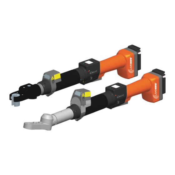
- Page 1 Instruction Manual P1962BA-EN REV H | 2023-07 47BC(...)/47BT(…) Cordless EC Tool For additional product information visit our website at www.ClecoTools.com...
- Page 2 Copyright © 2023 Apex Brands, Inc. All rights reserved. Disclaimer Apex Tool Group reserves the right to modify, supplement, or improve this document or the product without prior notice. Trademark Cleco is a registered trademark of Apex Brands, Inc. ® Apex Tool Group 670 Industrial Drive...
-
Page 3: Table Of Contents
Contents For This Instruction Manual ..............5 Safety ....................6 Warnings and Notes ....................6 Operator training ......................6 Intended use........................ 6 Standards ........................6 General Power Tool Safety Warnings................7 Specific Safety Instructions For Power Tools .............. 8 System Relevant Safety Instructions................8 Items delivered ................... - Page 4 11.4 Barcode scanner on tool ................... 31 11.5 Reset tool ........................32 Spare parts ..................33 12.1 Gear + Head T2X, T3X, T4X ..................33 12.2 HeadT2X ........................35 12.3 Head T3X ........................37 12.4 Head T4X ........................39 12.5 Socket for head T2X, T3X, T4X, optional ..............
-
Page 5: For This Instruction Manual
For This Instruction Symbols In The Text Manual Menu options (e.g.,Diagnostics) input italic fields, check boxes, radio buttons or The original language of this Instruction Manual is German. dropdown menus. This Instruction Manual is intended for any persons work- > Indicates selection of a menu option ing with this tool that do not carry out any programming from a menu, e.g., File >... -
Page 6: Safety
Safety The output can close by accidentally pressing the start button (e.g. when plac- ing the tool down). Fingers can be 2.1 Warnings and Notes squeezed or cut off. Do not reach into the open downforce. Warning notes are identified by a signal word and a picto- gram: •... -
Page 7: General Power Tool Safety Warnings
• this product may not cause harmful interference, and 2 Electrical Safety • this product must accept any interference received, a) Power tool plugs must match the outlet. Never including interference that may cause undesired oper- modify the plug in any way. Do not use any adapter ation. -
Page 8: Specific Safety Instructions For Power Tools
reach into the drive socket. To change the drive trolled with the switch is dangerous and must be socket, unplug the tool cable. repaired. d) Hold the tool firmly. Be prepared for torque reaction. Disconnect the plug from the power source and/or remove the battery pack, if detachable, from the e) Reaction bars are recommended in applications with power tool before making any adjustments, chang-... - Page 9 Repairs to the equipment are not permitted. Never pull the power cord to remove from an outlet. Send the controller to a Authorized Cleco Production Tools Sales & Service Center. Protect all cables from heat, oil, sharp edges and mov- ing parts.
-
Page 10: Items Delivered
Items delivered Check delivery for transit damage and ensure that all items have been supplied: • Cordless EC tool • This instruction manual • Declaration of Conformity • Tool Certificate • Machine Capability Analysis (MCA) Storage For short-term storage and for protection against damage ... -
Page 11: Product Description
Product description Item Designation LED lights for fast location of the fastening • Sturdy, brushless motor with resolver. Shutoff is position torque/angle-controlled. Power supply; battery pack 26 V illustrated • LCD display with information on status, torque, and angle. LCD display with information on torque, •... -
Page 12: Functional Elements
data transmission and for programming, place the tool in 5.1.3 Reverse switch the tool holder with IrDA interface port The reverse switch changes the rotation direction of the tool: 5.2.3 Identification – set torque (accessories, Clockwise rotation – for screwing optional) in screws ... - Page 13 • API license need to be checked. Perform test tightening with the new The MAC address is defined by Cleco and cannot be parameters. changed. The other data can be changed via infrared con- Tightening behavior may change nection of the tool to the controller.
-
Page 14: Accessories
6 Accessories Protection Scanner up to 50 Nm Order No.. 936424PT Battery pack 26 V HC, li-ion, 961101PT Order No. Protection, display Order No. 937210PT Battery pack 44 V HC, li-ion, 961102PT Order No. Battery charger 26/44 V, li-ion Order No. 962085PT Adapter cable PM48 Order No. -
Page 15: Prior To Initial Operation
Prior to initial operation The tool was preset by Apex Tool Group. A setting for your specific fastening sequence must only be made with the controller or a PC by a qualified person. For more informa- tion, refer to the programming manual. 7.1 Setting up tool holder Mount the tool holder on a stable base. -
Page 16: Initial Operation
Initial operation Operat- LED display Function ing status display Active Continuous light: screws Warning Red – Fasten- Data Risk of glove being pulled in due to rotating ing NOK transmis- machine parts. sion Green – Fasten- Risk of fingers being crushed or lost. ing OK Do not wear gloves when working with ... -
Page 17: Lcd Display
LCD display symbol at the top right shows an The LCD display on the tool is divided into the result dis- interrupted data connection to the T12.00 play, status display, operating menu and system error mes- control. A100 sages. 9.1 Result display 9.2 Status display The status display is divided into the "Standard"... - Page 18 Reject Release active. Optional - Reject Service The Reject Release was programmed in XXXXXX rundowns remaining until next Releas the control. service. Sync XXXXXX See Navigator > Advanced > Tool Group > Tightening > Reject Release. Optional - Depending on the programming, Serv.
-
Page 19: Operating Menu
Linking disabled. Linkin Synchronize the tool with the control locked once again. Synch Wait for end of transmission. Linkin Synchronize the tool with the control once again. 9.3 Operating menu 9.3.1 General The operating menu on the tool is divided into a main menu and submenus. - Page 20 9.3.2 Structure Main menu Administration Administration Date / Time Diagnosis Date Set position(optional) Counter status Scanner (optional) Serial number Software version Wireless transmission Servo Back Platform Back Diagnosis TQ calibration TQ measurement Angle encoder Voltages Speed Back Set position (optional) Next position Reset Linking Back...
- Page 21 9.3.3 Main menu Counter status Counte The tool counter display is incremented Shows general items such as Date/ after each rundown throughout the ser- >Main XXXXXX Time, Counter display, etc. Admini vice life of the tool. strati Refer to control under Diagnostics > Tool >...
- Page 22 9.3.5 Diagnostics submenu Angle encoder Angle The start button starts the tool at 30 % of A 360 TQ calibration the maximum speed. After one revolution Cal OK This test function cyclically recalibrates K 1.11 of the output shaft (nominal angle 360°), the system with the values used immedi- O 0.00 measured with the resolver, the tool is...
- Page 23 Displays EAP-TLS certificate. 9.3.6 Set position submenu – only with Certif The certificate is used for WLAN Linking enabled OK 01. encryption. 01.04 The display is only shown if a LiveWire tool is used with the L1 measuring card Selects the position to be used next. >Posit and EAP-TLS encryption is activated.
-
Page 24: System Error Messages
Wavebands display Subnet display Sub255 Wave- .255.2 bands 40.0 Display of channel currently used Gateway display Gat010 Active 122.0 channel 61.001 Display of channels scanned Display of tool designation in a network. Host ScanCh 122.0 1,5,9,7,2 61.001 Baud rate display SSID display SSID Baud rate... - Page 25 The servo's current sensor is detecting a The rundown counter could not be read Servo Tool current offset error. or written to. Error Error Return tool to Sales & Service Cen- Return tool to Sales & Service Cen- IOFF Counte ters for repair.
- Page 26 Additional messages from »PLUS« The service counter has reached the Depending on the software used, different messages relat- Servic warning threshold for the service inter- ing to the process with the PLUS system can be pro- interv val. grammed to appear on the display in addition to the warnng standard tool displays.
-
Page 27: Servicing
10 Servicing After Measures … fastening cycles 10.1 Cleaning instructions 100,000 Check to ensure the battery adapter, scanner and wireless For tools with a barcode scanner, the window must be free adapter are seated securely. of dirt. The barcode is not read if the window is dirty. ... -
Page 28: Troubleshooting
11 Troubleshooting 11.1 General tool Problem Possible cause Measure for mPro400GC Measure for mPro400S… (example SW 816841) (SW S816813) Tool doesn't start With counterclock- Parameterize Settings for speed left rotation. with counterclock- wise rotation, On the control screen On the control screen Main Menu > wise rotation acti- parameter for speed Navigator >... -
Page 29: Infrared Data Communication Between Controller And Tool
11.2 Infrared data communication between controller and tool Problem Possible cause Measure for mPro400GC Measure for mPro400S… (example SW 816841) (SW S816813) No infrared data Incorrect interface On the control screen On the control screen Main Menu communication selected for the con- Navigator >... - Page 30 Problem Possible cause Measure for mPro400GC Measure for mPro400S… (example SW 816841) (SW S816813) No WLAN data WLAN settings are On the control screen Tool Navi- On the control screen Main Menu communication different for control gator > Utilities > System Settings >...
-
Page 31: 11.4 Barcode Scanner On Tool
11.4 Barcode scanner on tool Problem Possible cause Measure for mPro400GC Measure for mPro400S… (example SW 168841) (SW S168813) The barcode scan- Parameters for Part On the control screen Press < > on the control. ner is not activated ID not set to Acti- Select the required tool under TM Navigator >... -
Page 32: Reset Tool
11.5 Reset tool This key combination activates the Service menu. Here, the tool can be shut off or reset to the delivery set- tings. Note The following will then be deleted: • the internal memory (programming) • the current fastening job •... -
Page 33: Spare Parts
Spare parts Always use only original Cleco spare parts. Failure to comply with this instruction can result in decreased performance and an increased need for servicing. Installing spare parts from other manufacturers will void all manufacturer's warranties. Information, but no warning of hazards. - Page 34 Index Order no. Quantity Description Dimensions 800116 circlip 25,98X0,94 IR 541887 washer 542724 o-ring 28,24X 0,78 542722 gear ring 541899 pinion gear 541894 idler gear 923095 needle bearing 3,X5,X 7, 542230 planet carrier 541888 needle roller 541894 idler gear 923095 needle bearing 3,X5,X 7, 542079...
-
Page 35: Headt2X
12.2 HeadT2X 540395 10.3 Lubricants, page 27 Apex Tool Group P1962BA | REV H | 2023-07... - Page 36 Index Order no. Quantity Description Dimensions ball bearing 500538 needle bearing 303161 thrust race 9,58X 20,37X 0,79 249145 thrust bearing 1011671 Needle Bearing 542958 Ratchet 542922 Spring 537316 pinion gear 537385 gear 537386 bevel gear spindle 542931 Cover 1463 Grease Fitting 543205 Dowel Pin (4 mm Dia.
-
Page 37: Head T3X
12.3 Head T3X 540395 10.3 Lubricants, page 27 Apex Tool Group P1962BA | REV H | 2023-07... - Page 38 Index Order no. Quantity Description Dimensions ball bearing 500538 needle bearing 303161 thrust race 9,58X 20,37X 0,79 249145 thrust bearing 1011671 Needle Bearing 542921 Ratchet 542922 Spring 537316 pinion gear 537385 gear 537386 bevel gear spindle 542917 Housing 1463 Grease Fitting 543207 Dowel Pin 543208...
-
Page 39: Head T4X
12.4 Head T4X 540395 10.3 Lubricants, page 27 Apex Tool Group P1962BA | REV H | 2023-07... - Page 40 Index Order no. Quantity Description Dimensions ball bearing 500538 needle bush 303161 thrust washer 9,58X 20,37X 0,79 249145 axial needle bearing 1011671 needle bearing 542921 ratchet 542922 compression spring 537316 needle sleeve 537385 pinion gear 537386 gear 542917 bevel gear spindle 1463 housing 543207...
-
Page 41: Socket For Head T2X, T3X, T4X, Optional
12.5 Socket for head T2X, T3X, T4X, optional Index Hexagon socket size Flush Extended 1/4" Extended 1/2" Extended 3/4" Extended 1" (6,35 mm) (12,7 mm) (19 mm) (25,4 mm) Head T2X 1/4” KS2EA0… KS2EA2… KS2EA4… KS2EA6… KS2EA8… 5/16” KS2EB0… KS2EB2… KS2EB4…... - Page 42 Index Hexagon socket size Flush Extended 1/4" Extended 1/2" Extended 3/4" Extended 1" (6,35 mm) (12,7 mm) (19 mm) (25,4 mm) Head T4X 1/2” KS4EE0… KS4EE2… KS4EE4… KS4EE6… KS4EE8… 9/16” KS4EF0… KS4EF2… KS4EF4… KS4EF6… KS4EF8… 5/8” KS4EG0… KS4EG2… KS4EG4… KS4EG6… KS4EG8…...
-
Page 43: Gear + Head (C1, C3)
12.6 Gear + Head (C1, C3) TAB.2 301071 15° 47BC…30C1 301072 30° 47BC…30C3 933027 10.3 Lubricants, page 27 Apex Tool Group P1962BA | REV H | 2023-07... - Page 44 Index Order no. Quantity Description Dimensions 800116 circlip 25,98X0,94 IR 541887 washer 542724 o-ring 28,24X 0,78 542722 gear ring 541893 idler gear 541487 needle bearing 3,X5,X 7, 542232 planet carrier 541888 needle roller 541897 idler gear 541487 needle bearing 3,X5,X 7, 542099 planet carrier 502983...
-
Page 45: Head 301071 (C1)
12.7 Head 301071 (C1) 541444, 541445 10.3 Lubricants, page 27 Note: ALWAYS replace Bevel Gear and Bevel Pinion in pairs since both should wear equally. Apex Tool Group P1962BA | REV H | 2023-07... - Page 46 Index Order no. Quantity Description Dimensions 202127 Zahnrad 202128 Zahnrad 812164 Spannstift 833075 Stift 833785 Mutter Schraubeinsatz 842980 Stahlkugel 2,381 (3/32") 843589 Schmiernippel 843827 Nadellager 847027 Flachkopfschraube 847095 Rillenkugellager 847746 Nadellager 847747 Ring 861690 15° Zahnradsatz 863462 Schraube 864201 Kugellagerhalter 864202 Nadellager 864264...
-
Page 47: Head 301072 (C3)
12.8 Head 301072 (C3) 541444, 541445 10.3 Lubricants, page 27 Note: ALWAYS replace Bevel Gear and Bevel Pinion in pairs since both should wear equally. Apex Tool Group P1962BA | REV H | 2023-07... - Page 48 Index Order no. Quantity Description Dimensions 202127 gear wheel 202128 gear wheel 812164 dowel pin 833075 833785 socket 842980 Steel ball 2,381 (3/32") 843589 lubrication nipple 843827 needle bearing 847027 847095 ball bearing 847746 needle bearing 847747 ring 861691 30° gear set 863462 metering screw 864201...
-
Page 49: Socket For C1, C3, Optional
12.9 Socket for C1, C3, optional Index Hexagon Socket Size Flush Extended 1/2" Extended 3/4" (12,7 mm) (19 mm) 1/4" CSEA01 CSEA41 CSEA61 3/8" CSEC01 CSEC41 CSEC61 7/16" CSED01 CSED41 CSED61 1/2" CSEE01 CSEE41 CSEE61 9/16" CSEF01 CSEF41 CSEF61 7 mm CSMA01 CSMA41 CSMA61... -
Page 50: Tool Holder
12.10Tool holder TAB 3 Order no. IrDA For tool (…) 935290 × 935303 935170 917735 47BT(…) 935292 935395 – – – – 935999 × 47BC(…) 935303 935170 917735 935942 935998 – – – – Index Order no. Quantity Description Dimension S900983 40 X 40 S900418... -
Page 51: Technical Data
13 Technical Data 13.1Dimensions 47BT(…)20T2 Without scanner Scanner L3 L4 L3 L4 47BTYB20T2 14,2 – – 47BTYSB20T2 14,2 43 18 dargestellt: 47BTXSB20T2 47BTRSB20T2 47BTBSB20T2 47BTZSB20T2 47BTYSB20T2 66.2 121.1 98.9 80.5 93.5 12.7 43.3 13.2Dimensions 47BT(…)30T3 Without scanner Scanner L3 L4 L1-1 L3 L4 47BTYB30T3... -
Page 52: Dimensions 47Bt
13.3Dimensions 47BT(…)40T4 Without scanner Scanner L3 L4 L3 L4 47BTYB40T4 14,2 – – 47BTYSB40T4 14,2 43 18 50.8 dargestellt: 47BTXSB40T4 47BTRSB40T4 47BTBSB40T4 47BTZSB40T4 79.1 47BTYSB40T4 121.1 22.8 80.5 93.5 105.2 13.4Dimensions 47BC(…)30C1 Without scanner Scanner L3 L4 L3 L4 47BCYB30C1 14,2 –... -
Page 53: Dimensions 47Bc
13.5Dimensions 47BC(…)30C3 Without Scanner Scanner L3 L4 L3 L4 47BCYB30C3 14,2 – – 47BCYSB30C3 14,2 43 65 dargestellt: 47BCXSB30C3 47BCRSB30C3 47BCBSB30C3 47BCZSB30C3 121.1 222.3 80.5 93.5 Dimension of tool holder 935290 / 935395 (optional) Apex Tool Group P1962BA | REV H | 2023-07... -
Page 54: Performance Data
Dimension of tool holder 935999 / 935998 (optional) 13.6Performance data Parameter Tool Memory Type Screw size Weight without Recommended Free speed Calibration data Static Cur- Accu torque range rent Factor Accu- PM48, Accu- Torque Angle pulses ft.-lbs (Nm) pack 26 V pack 44 V (nominal) (Resolver) -
Page 55: Electrical Data
13.7Electrical Data 13.7.1Output stage servo electronics Features Data Transmission power: 18 dBm EIRP (radiated) Features Data Sensitivity -95 dBm (typ. @ EIRP Nominal motor phase cur- 8 A peak value, sine 2,4 GHz) rent -89 dBm (typ. @ EIRP Rated output 150 VA 5 GHz) Maximum power... -
Page 56: Service
If service is required to change the torque transducer, the screw electronic system or if a recalibration is required, please send the Cleco tool to Sales & Service Center. This will ensure that after the service work, any required calibra- tion data update is carried out properly. - Page 57 Apex Tool Group P1962BA | REV H | 2023-07...
- Page 58 POWER TOOLS SALES & SERVICE CENTERS Please note that all locations may not service all products. Contact the nearest Cleco® Sales & Service Center for the appropriate facility to handle your service requirements. Sales Center Service Center NORTH AMERICA | SOUTH AMERICA...
Need help?
Do you have a question about the LiveWire 47BC Series and is the answer not in the manual?
Questions and answers