Cleco NeoTek 30 Series Instruction Manual
Hide thumbs
Also See for NeoTek 30 Series:
- Instruction manual (76 pages) ,
- Instruction manual (42 pages) ,
- Instruction manual (44 pages)
Table of Contents
Advertisement
Available languages
Available languages
Quick Links
Advertisement
Table of Contents

Subscribe to Our Youtube Channel
Related Manuals for Cleco NeoTek 30 Series


Summary of Contents for Cleco NeoTek 30 Series
- Page 1 TM12-1109-INT REV G l 2023-09 30 & 50 & 70 Series Instruction Manual | Corded Assembly Tool Bedienungsanleitung | Kabelgebundenes Montagewerkzeug Manuel d'utilisation | Outil de montage filaire...
- Page 2 Disclaimer Apex Tool Group reserves the right to modify, supplement, or improve this document or the product with- out prior notice. Trademark Cleco® is a registered trademark of Apex Brands, Inc. Manufacturer Apex Tool Group 670 Industrial Drive Lexington, SC 29072...
-
Page 3: Table Of Contents
Content About this Document ...................... 5 Safety ..........................5 Warnings and Notices ..................... 5 Symbols on the Product ....................6 Intended Use ........................6 Foreseeable misuse ....................... 6 Operator Training ......................6 Standards........................6 General Power Tool Safety Warnings ................6 Specific Safety Instructions for Power Tools .............. - Page 4 Elektrische Daten ......................29 Umgebungsbedingungen ....................30 Fehlersuche ........................30 Entsorgung........................32 À propos de ce document ..................... 33 Sécurité ......................... 33 Avertissements et remarques ..................33 Symboles figurant sur le produit ................... 34 Utilisation conforme à l'usage prévu ................34 Mauvais usage prévisible .....................
-
Page 5: About This Document
• Indicates lists, level 1. About this Document Indicates lists, level 2. This document is intended for qualified employees respon- Indicates options. sible for installation and maintenance (installer, mainte- nance technician, service, operator). It contains information ➢ Indicates results. • for safe and appropriate handling of the product. -
Page 6: Symbols On The Product
Structure Of Warnings Standards It is mandatory that national, state, and local codes and Caution standards be followed. Type and source of danger. Possible consequences of non-observance. FCC- and IC Compliance ► Measures to avoid danger. This product complies with Part 15 of the FCC Rules. Any changes or modifications not expressly approved by the Symbols on the Product manufacturer could void the user's authority to operate this... -
Page 7: Specific Safety Instructions For Power Tools
liquids, gases or dust. Power tools create sparks moving parts. Loose clothes, jewellery or long hair which may ignite the dust or fumes. can be caught in moving parts. Keep children and bystanders away while operat- If devices are provided for the connection of dust ing a power tool. -
Page 8: Items Supplied
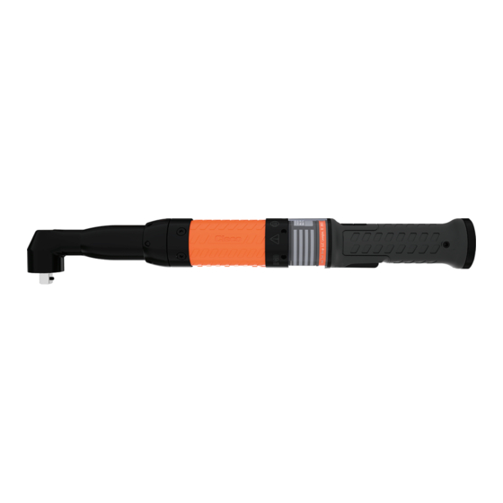
Our insulation is not insulation in the sense of VDE Product Description standards: Hold the device at the insulated handle surfaces when you perform work where the screw can Tool strike hidden power lines or your own power cable. • Contact between the screw and a live power line Quarter turn tool cable connection •... -
Page 9: Before Initial Operation
Default Settings Before Initial Operation Blue Green Yellow Connect tool Light ► Connect the tool via tool cable to the controller (see Quick Installation Guide). Tool Run- OK run- NOK run- User de- scrip- ning down down fined tion Maintenance Implement a comprehensive safety maintenance program to provide regular inspection for all phases of tool operation and power supply. - Page 10 Tool Depending on which event oc- Measures curs earlier: Time interval Cycles ► Send the tool to a certified Sales & Ser- 70ESN355SD8 24 months 250,000 vice Center for assessment. 70ESR355SZ8 70ESN475SD8 70ESR475SZ8 70ESN700SD8 70ESR700SZ8 70ESN850SD8 70ESN850SZ8 70ESN1500TA8T 70ESR1500SZ8 70ESN2000TA8T 70ESR2000SZ8 70ESN4000UA12MT Dynamic Service Counter...
-
Page 11: Technical Data
Technical Data Right Angle Side Out- Torque Range Speed Weight Length Height Center Emissions (ft-lb) (ft-lb) Order no. Min. Max. r/min (lb) (in) (in) (in) Serie 30 1.13 380.0 36.0 12.3 30EAN06EA3 2925 <70 <2.5 1.5 (0.9) (4.4) (2.5) (15.0) (1.42) (0.48) 3/8"... -
Page 12: Pistol
Side Out- Torque Range Speed Weight Length Height Center Emissions (ft-lb) (ft-lb) Order no. Min. Max. r/min (lb) (in) (in) (in) 88.0 350.0 7.00 655.1 68.0 38.0 70EAN350PA6 <70 <2.5 1.5 (64.9) (258.1) (15.43) (25.8) (2.68) (1.49) 3/4" 53.0 53.0 70EAN500RA6 <70 <2.5 1.5... -
Page 13: Inline
Order no. Torque Range Speed Weight Length Side to Output Emissions Center (ft-lb) (ft-lb) Min. Max. r/min (lb) (in) (in) Serie 50 1.58 16.3 50EPN28FD3 2125 3/8" <70 <2,5 1,5 (4.1) (20.6) (3.48) (10.07) (0.64) 1.65 18.9 50EPN43GD3 1375 3/8" <70 <2,5 1,5 (6.6) (31.7) - Page 14 Order no. Torque Range Speed Weight Length Side to Output Emissions Center (ft-lb) (ft-lb) Min. Max. r/min (lb) (in) (in) 66.0 1.90 434.8 22.0 50ESN65HD4 1/2" <70 <2.5 1.5 (10.3) (48.6) (4.19) (17.1) (0.86) 84.0 2.00 449.2 22.0 50ESN85JD4 1/2" <70 <2.5 1.5 (12.5) (61.9)
- Page 15 Order no. Torque Range Speed Weight Length Side to Output Emissions Center (ft-lb) (ft-lb) Min. Max. r/min (lb) (in) (in) 1500 70ESN1500TA8T 71.6 <2.5 1.5 1" (313) (1106.3) (19.2) (24.4) (1.6) 2000 70ESN2000TA8T 1" 72.7 <2.5 1.5 (572) (1475.1) (19.2) (24.4) (1.6) 1250...
-
Page 16: Electrical Data
Electrical Data Features Data Series 30, 50 Series 70 Supply Voltage, Single Phase 100–240±10 % 230±10 % [VAC] Rated Supply Current [A] 2–1 2–1 Frequency [Hz] 50–60 50–60 Peak Current [A] Rated Power [max. VA] 1600 1600 Idling [VA] Protection class nach Protection separation Protection separation DIN EN 61140... - Page 17 Problem Possible cause Measure Tool starts in tightening direction, No speed programmed for Parameterize Speed left rotation but not in counterclockwise rota- counterclockwise rotation. ► Select on the controller Navigator > Stand- tion. ard > Tool Groups > Settings For Speed Left Rotation.
-
Page 18: Disposal
Disposal Components and auxiliary materials of the product pose risks to the health and the environment. The tool contains com- ponents that can be recycled as well as components that must be specially disposed of. ► Catch auxiliary materials (oils, greases) when drained and dispose of them properly. ►... -
Page 19: Zu Diesem Dokument
• Kennzeichnet Listen, Ebene 1. Zu diesem Dokument Kennzeichnet Listen, Ebene 2. Dieses Dokument richtet sich an Fachkräfte für Installation Kennzeichnet Optionen und Instandhaltung (Einrichter, Instandhalter, Service, Be- treiber). Es enthält Informationen ➢ Kennzeichnet Resultate. • für eine sichere, sachgerechte Verwendung. 1. -
Page 20: Symbole Auf Dem Produkt
Aufbau Warnhinweis Ausbildung des Personals Das Produkt wurde von Apex Tool Group voreingestellt. Vorsicht Änderungen an den Werkseinstellungen dürfen nur von Art und Quelle der Gefahr. einer Fachkraft durchgeführt werden Mögliche Folgen bei Nichtbeachtung. ► Maßnahmen zur Vermeidung der Ge- Normen/Standards fahr. - Page 21 Elektrowerkzeuge (mit Netzleitung) oder auf akkube- Schutzausrüstung, wie Staubmaske, rutschfeste triebene Elektrowerkzeuge (ohne Netzleitung). Sicherheitsschuhe, Schutzhelm oder Gehörschutz, je nach Art und Einsatz des Elektrowerkzeuges, verrin- gert das Risiko von Verletzungen. 1 Arbeitsplatzsicherheit Vermeiden Sie eine unbeabsichtigte Inbe- Halten Sie Ihren Arbeitsbereich sauber und gut triebnahme.
-
Page 22: Spezielle Sicherheitshinweise Für Elektrowerkzeuge
Primary-Steuerung mPro(…)GCD-(…) max. 50 m Pflegen Sie Elektrowerkzeuge mit Sorgfalt. Kontrollieren Sie, ob bewegliche Teile einwandfrei Secondary-Steuerung mPro-400GCD-S(…) funktionieren und nicht klemmen, ob Teile ge- max. 30 m brochen oder so beschädigt sind, dass die Funk- ► Bei Verwendung von Werkzeug Serie 70 folgendes tion des Elektrowerkzeuges beeinträchtigt ist. -
Page 23: Vor Der Inbetriebnahme
LED-Anzeige Der LED-Leuchtring ist über die Benutzerschnittstelle der Steuerung konfigurierbar. Werkseinstellungen LED- Blau Grün Gelb Licht Beschr Werkzeug NIO- eibung läuft Verschrau Verschrau nutzerde- bung bung finiert Vor der Inbetriebnahme Werkzeug anschließen ► Das Werkzeug mit dem Werkzeugkabel an der Steuerung anschließen (siehe Kurzanleitung). - Page 24 Werkzeug Je nachdem, welches Ereignis Maßnahme früher eintritt: Zeitintervall Schraubzyklen ► Werkzeug zur Beurteilung an ein zer- Serie 70 Winkel 36 Monate 1.000.000 tifiziertes Sales & Service Center 70EAN155NA6 schicken. 70EAN205NA6 ► Werkzeug zur Beurteilung an ein zer- 70EAN240PA6 36 Monate 500.000 tifiziertes Sales &...
- Page 25 Während des Schraubablaufes wird kontinuierlich das Spitzen-Drehmoment ermittelt. Nachdem der Schraubablauf abgeschlossen ist, wird das erreichte Spitzen-Drehmoment einem der Belastungsbereiche zugeordnet. Jedem Belas- tungsbereich ist ein Faktor zugewiesen, mit dem die Verschraubung gezählt wird. Belastungsbereich Faktor 2,00 1,25 1,00 0,83 0,71 0,50 Beispiel:...
-
Page 26: Technische Daten
Technische Daten Winkel Seite Drehmoment- Dreh- Gewich bereich zahl Länge Höhe Mitte Emissionen Bestell-Nr. Min. Max. 1/min Abtrieb Serie 30 30EAN06EA3 2925 1,13 36,0 12,3 3/8" <70 <2.5 1.5 30EAN12EA3 1450 1,14 36,0 12,3 3/8" <70 <2.5 1.5 30EAN21FA3 1,32 40,3 16,4 3/8"... -
Page 27: Pistole
Pistole Seite Drehmoment- Dreh- bereich zahl Gewicht Länge Mitte Emissionen Bestell-Nr. Min. Max. 1/min Abtrieb Serie 30 30EPN05BDQ 4275 0,91 16,3 1/4" <70 <2,5 1,5 30EPN05BD2 4275 0,93 16,3 1/4" <70 <2,5 1,5 30EPN12EAQ 11,6 1650 1,00 16,3 1/4" <70 <2,5 1,5 30EPN12FA3 11,6... - Page 28 Seite Drehmoment- Dreh- bereich zahl Gewicht Länge Mitte Emissionen Bestell-Nr. Min. Max. 1/min Abtrieb 30ESN12FA3 11,6 1650 1,06 357,2 16,3 3/8" <70 <2.5 1.5 30ESN19FB3 19,0 1000 1,06 357,2 16,3 3/8" <70 <2.5 1.5 30ESN26FC3 26,0 1,06 357,2 16,3 3/8" <70 <2.5 1.5 Serie 50 50ESN28FD3...
-
Page 29: Elektrische Daten
Seite Drehmoment- Dreh- bereich zahl Gewicht Länge Mitte Emissionen Bestell-Nr. Min. Max. 1/min Abtrieb 70ESN1500TA8T 1500 71.6 <2.5 1.5 1" 70ESN2000TA8T 2000 72.7 <2.5 1.5 1" 70ESN4000UA12MT 1250 4000 12,8 73.2 <2.5 1.5 1/2" Seite Drehmoment- Dreh- bereich zahl Gewicht Länge Mitte Emissionen... -
Page 30: Umgebungsbedingungen
Merkmale Daten Serie 30, 50 Serie 70 Leistung Leerlauf [VA] Schutzklasse nach DIN EN 61140 Schutztrennung Schutztrennung Umgebungsbedingungen Merkmale Daten Einsatzort In Innenräumen 0 °C – 45 °C Arbeitstemperatur -25 °C – 70 °C Lagertemperatur Kühlungsart Konvektion (Eigenkühlung) 10 % – 90 % keine Betauung Relative Luftfeuchtigkeit Arbeitshöhe Bis 3 000 m über NN... - Page 31 Problem Mögliche Ursache Maßnahme Werkzeug schaltet bei gewün- Schwellenmoment ist zu hoch. Anzugssequenz korrigieren oder Schwel- schtem Drehmoment ab, jedoch lenmoment reduzieren. ohne Winkelanzeige. ► Sicherstellen, dass der Bediener den Werkzeug schaltet vorzeitig ab. Bediener lässt Startschalter los, bevor die Steuerung das Startschalter die gesamte Sequenz über Werkzeug abschaltet.
-
Page 32: Entsorgung
Entsorgung Bestandteile und Hilfsmittel des Produkts bergen Risiken für Gesundheit und Umwelt. Das Produkt enthält Bauteile, die wiederverwertet werden können, sowie Bauteile, die speziell entsorgt werden müssen. ► Hilfsstoffe (Öle, Fette) beim Ablassen auffangen und fachgerecht entsorgen. ► Bestandteile der Verpackung trennen und sortenrein entsorgen. ►... -
Page 33: À Propos De Ce Document
<...> Caractérise les interrupteurs, boutons ou À propos de ce document touches d'un clavier externe, p. ex. <F5>. Courier Caractérise les noms de fichier, par ex. Dieses Dokument richtet sich an Fachkräfte für Installation setup.exe. und Instandhaltung (Einrichter, Instandhalter, Service, Be- treiber). -
Page 34: Symboles Figurant Sur Le Produit
• Utilisation uniquement dans des processus de Remarque vissage industriels. Un symbole en relation avec le mot Re- • Conjointement avec les composants énumérés dans marque caractérise une éventuelle situation la déclaration CE de conformité. dommageable qui, si elle n'est pas évitée, •... -
Page 35: Consignes Générales De Sécurité Pour Les Outils Électriques
contre les interférences nuisibles lorsque le produit est uti- câbles de raccordement endommagés ou emmêlés lisé dans un environnement commercial. Ce produit gé- augmentent le risque d'un choc électrique. nère, utilise et peut émettre de l'énergie radiofréquence et, Lorsque vous travaillez en extérieur avec un outil s'il n'est pas installé... -
Page 36: Consignes Spéciales De Sécurité Pour Les Outils Électriques
de manière plus sûre dans la plage de puissance in- mettre sous tension des parties métalliques de l'appa- diquée. reil et provoquer un choc électrique. N'utilisez aucun outil électrique dont l'interrupteur Tenez fermement l'outil dans la main. Tenez compte est défectueux. Un outil électrique, qui ne peut plus d'un couple de réaction rapidement variable. -
Page 37: Description Du Produit
Description du produit Affichage à LED La bague lumineuse LED est configurable via l'interface Outil utilisateur de la commande. • Connexion du câble de l'outil avec quart de tour • Bagues lumineuses LED configurables Réglages usine • Marche à droite / à gauche Éclair- Bleu Vert... - Page 38 Outil En fonction de l'événement qui se produit le plus Mesure tôt : Intervalle de Cycles de vissage temps ► Contrôler toutes les Toutes les séries Une fois par jour connexions. ► Effectuer un contrôle visuel à la recherche de dommages d'ordre gé- néral.
- Page 39 Plage de charge Valeur de couple en pourcentage de la capacité de l'outil 95,000 % – 100 % 90,000 % – 94,999 % 80,000 % – 89,999 % 55,000 % – 79,999 % 3,000 % – 54,999 % 0,000 % – 2,999 % Le couple maximal est déterminé...
-
Page 40: Caractéristiques Techniques
Caractéristiques techniques Angle Vitess Lon- Hau- Côté à Plage de couple Poids gueur teur centre Émissions Réf. min. max. 1/min Sortie Serie 30 30EAN06EA3 2925 1,13 36,0 12,3 3/8" <70 <2.5 1.5 30EAN12EA3 1450 1,14 36,0 12,3 3/8" <70 <2.5 1.5 30EAN21FA3 1,32 40,3... -
Page 41: Pistolet
Pistolet Réf. Plage de couple Vitesse Poids Lon- Côté à Sortie Émissions gueur centre Min. Max. 1/min Serie 30 30EPN05BDQ 4275 0,91 16,3 1/4" <70 <2,5 1,5 30EPN05BD2 4275 0,93 16,3 1/4" <70 <2,5 1,5 30EPN12EAQ 11,6 1650 1,00 16,3 1/4"... - Page 42 Réf. Plage de couple Vitesse Poids Lon- Côté à Sortie Émissions gueur centre Min. Max. 1/min 30ESN19FB3 19,0 1000 1,06 357,2 16,3 3/8" <70 <2.5 1.5 30ESN26FC3 26,0 1,06 357,2 16,3 3/8" <70 <2.5 1.5 Serie 50 50ESN28FD3 28,0 2125 1,35 398,5 16,3...
-
Page 43: Caractéristiques Électriques
Réf. Plage de couple Vitesse Poids Lon- Côté à Sortie Émissions gueur centre Min. Max. 1/min 70ESN1500TA8T 1500 71.6 <2.5 1.5 1" 70ESN2000TA8T 2000 72.7 <2.5 1.5 1" 70ESN4000UA12MT 1250 4000 12,8 73.2 <2.5 1.5 1/2" Réf. Plage de couple Vitesse Poids Lon-... -
Page 44: Conditions Ambiantes
Critères Données Série 30, 50 Série 70 Classe de protection selon Protection Protection DIN EN 61140 Conditions ambiantes Critères Caractéristiques Lieu d'utilisation Dans les espaces intérieurs Température ambiante 0 °C - 45 °C -25 °C – 70 °C Température de stockage Type de refroidissement Convection (refroidissement indépendant) 10 % –... - Page 45 Problème Cause possible Mesure L'outil est désactivé lorsque le Corriger la séquence de serrage ou réduire le cou- Le couple seuil est trop élevé. couple souhaité est atteint, ce- ple seuil. pendant sans affichage de l'angle. ► S'assurer que l'opérateur maintienne enfoncé L'outil est désactivé...
-
Page 46: Mise Au Rebut
Mise au rebut Les composants et les moyens auxiliaires du produit comportent des risques pour la santé et l'environnement. L'outil contient des composants recyclables ou nécessitant une mise au rebut spéciale. ► Récupérer les matières consommables (huiles, graisses) lors de la vidange et les éliminer dans les règles de l'art. ►... - Page 48 POWER TOOLS SALES & SERVICE CENTERS Please note that all locations may not service all products. Contact the nearest Cleco® Sales & Service Center for the appropriate facility to handle your service requirements. Sales Center Service Center NORTH AMERICA | SOUTH AMERICA...
Need help?
Do you have a question about the NeoTek 30 Series and is the answer not in the manual?
Questions and answers