
Related Manuals for Cleco LiveWire 47BS Series


Summary of Contents for Cleco LiveWire 47BS Series
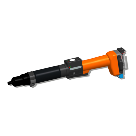
- Page 1 Instruction Manual P2270BA-EN REV D | 2023-07 47BS... Cordless EC Tool For additional product information visit our website at www.ClecoTools.com...
- Page 2 Copyright © 2023 Apex Brands, Inc. All rights reserved. Disclaimer Apex Tool Group reserves the right to modify, supplement, or improve this document or the product without prior notice. Trademark Cleco is a registered trademark of Apex Brands, Inc. ® Apex Tool Group 670 Industrial Drive...
-
Page 3: Table Of Contents
Contents For This Instruction Manual ..............5 Safety ....................6 Warnings and Notes ....................6 Operator training ......................6 Intended use........................ 6 Standards ........................6 General Power Tool Safety Warnings................7 Specific Safety Instructions For Power Tools .............. 8 System Relevant Safety Instructions................8 Items delivered ................... - Page 4 11.3 WLAN data communication between controller and tool........... 30 11.4 Reset tool ........................32 Spare parts ..................33 12.1 Gearing + Attachment 942246PT ................33 12.2 Gearing + Attachment 942240PT ................35 12.3 Gearing + Attachment 942242PT ................37 12.4 Gearing 942238PT, 942239PT..................
-
Page 5: For This Instruction Manual
For This Instruction Symbols In The Text Manual Menu options (e.g.,Diagnostics) input italic fields, check boxes, radio buttons or The original language of this Instruction Manual is German. dropdown menus. This Instruction Manual is intended for any persons work- > Indicates selection of a menu option ing with this tool that do not carry out any programming from a menu, e.g., File >... -
Page 6: Safety
Safety CE compliant The product corresponds to the pre- scribed technical requirements in Europe. 2.1 Warnings and Notes Warning notes are identified by a signal word and a picto- gram: Read all instructions. • The signal word describes the severity and probability of the impending danger. -
Page 7: General Power Tool Safety Warnings
• this product may not cause harmful interference, and 2 Electrical Safety • this product must accept any interference received, a) Power tool plugs must match the outlet. Never including interference that may cause undesired oper- modify the plug in any way. Do not use any adapter ation. -
Page 8: Specific Safety Instructions For Power Tools
Personal Protective Equipment trolled with the switch is dangerous and must be repaired. Risk of injury by being wound up in and caught by machin- Disconnect the plug from the power source and/or remove the battery pack, if detachable, from the a) When working with rotating parts, it is not permitted to power tool before making any adjustments, chang- wear gloves. - Page 9 Never pull the power cord to remove from an outlet. Send the controller to a Authorized Protect all cables from heat, oil, sharp edges and mov- Cleco Production Tools Sales & Service Center. ing parts. Replace damaged cables immediately.
-
Page 10: Items Delivered
Items delivered Check delivery for transit damage and ensure that all items have been supplied: • Cordless EC tool • This instruction manual • Declaration of Conformity • Tool Certificate • Machine Capability Analysis (MCA) Storage For short-term storage and for protection against damage ... -
Page 11: Product Description
Product description Item Designation Wireless module • Sturdy, brushless motor with resolver. Shutoff is LiveWire Memory Chip (LMC) torque/angle-controlled. • LCD display with information on status, torque, and angle. 5.1 Operation elements • Green OK and red NOK LED display provides informa- tion about current fastening result. -
Page 12: Functional Elements
data transmission and for programming, place the tool in 5.1.3 Reverse switch the tool holder with IrDA interface port The reverse switch changes the rotation direction of the tool: 5.2.3 Identification – set torque (accessories, Clockwise rotation – for screwing optional) in screws ... - Page 13 • API license need to be checked. Perform test tightening with the new The MAC address is defined by Cleco and cannot be parameters. changed. The other data can be changed via infrared con- Tightening behavior may change nection of the tool to the controller.
-
Page 14: Accessories
6 Accessories Battery pack 26 V HC, li-ion, 961101PT Order No. Battery pack 44 V HC, li-ion, 961102PT Order No. Battery charger 26/44 V, li-ion Order No. 962085PT Adapter cable PM48 Order No. 961341-030 – 3 m Order No. 961341-060 – 6 m Order No. -
Page 15: Prior To Initial Operation
Prior to initial operation 7.4 Changing LMC Note The tool was preset by Apex Tool Group. A setting for your specific fastening sequence must only be made with the Electrostatically sensitive component. controller or a PC by a qualified person. For more informa- The electronic assemblies of the cordless tion, refer to the programming manual. -
Page 16: Performing A Software Update
Fig. 7-4: Inserting LMC 7.5 Performing a software update Perform update, see document P2372JH. Do not remove the battery pack during the software update! P2270BA | REV D | 2023-07 Apex Tool Group... -
Page 17: Initial Operation
Initial operation Operating LED display LCD dis- status play Stay alive Red-green flasing light Warning alternately Risk of glove being pulled in due to rotating machine parts. Risk of fingers being crushed or lost. Do not wear gloves when working with ... -
Page 18: Lcd Display
LCD display symbol at the top right shows an The LCD display on the tool is divided into the result dis- interrupted data connection to the T12.00 play, status display, operating menu and system error mes- control. A100 sages. 9.1 Result display 9.2 Status display ... - Page 19 Reject Release active. Optional - Reject Service The Reject Release was programmed in XXXXXX rundowns remaining until next Releas the control. service. Sync XXXXXX See Navigator > Advanced > Tool Group > Tightening > Reject Release. Optional - Depending on the programming, Serv.
-
Page 20: Operating Menu
Linking disabled. Linkin Synchronize the tool with the control locked once again. Synch Wait for end of transmission. Linkin Synchronize the tool with the control once again. 9.3 Operating menu 9.3.1 General The operating menu on the tool is divided into a main menu and submenus. - Page 21 9.3.2 Structure Main menu Administration Administration Date / Time Diagnosis Date Set position(optional) Counter status Scanner (optional) Serial number Software version Wireless transmission Servo Back Platform Back Diagnosis TQ calibration TQ measurement Angle encoder Voltages Speed Back Set position (optional) Next position Reset Linking Back...
- Page 22 9.3.3 Main menu Counter status Counte The tool counter display is incremented Shows general items such as Date/ after each rundown throughout the ser- >Main XXXXXX Time, Counter display, etc. Admini vice life of the tool. Refer to control strati under Diagnostics >...
- Page 23 9.3.5 Diagnostics submenu Angle encoder Angle The start button starts the tool at 30 % of A 360 TQ calibration the maximum speed. After one revolution Cal OK This test function cyclically recalibrates K 1.11 of the output shaft (nominal angle 360°), the system with the values used immedi- O 0.00 measured with the resolver, the tool is...
- Page 24 Displays EAP-TLS certificate. 9.3.6 Set position submenu – only with Certif The certificate is used for WLAN Linking enabled OK 01. encryption. 01.04 The display is only shown if a LiveWire tool is used with the L1 measuring card Selects the position to be used next. >Posit and EAP-TLS encryption is activated.
-
Page 25: System Error Messages
Display of channel currently used Gateway display Gat010 Active 122.0 channel 61.001 Display of channels scanned Display of tool designation in a network. Host ScanCh 122.0 1,5,9,7,2 61.001 Baud rate display SSID display SSID Baud rate Only a maximum of the first 12 charac- APEX ters are displayed. - Page 26 Collective servo error caused by hard- Tool memory could not be read. Servo Tool ware. Return tool to Sales & Service Cen- Error Error Return tool to Sales & Service Cen- ters for repair. Other Ident ters for repair. The current setpoint has been Two-stage start button defective.
- Page 27 Additional messages from »PLUS« The service counter has reached the Depending on the software used, different messages relat- Servic maximum number of rundowns. Tool ing to the process with the PLUS system can be pro- Interv has locked. grammed to appear on the display in addition to the standard tool displays.
-
Page 28: Servicing
10 Servicing After Measures … fastening cycles 10.1 Cleaning instructions 2.5 million General refurbishment of tool. Send it to Sales & Service Center. For tools with a barcode scanner, the window must be free of dirt. The barcode is not read if the window is dirty. a. -
Page 29: Troubleshooting
11 Troubleshooting 11.1 General tool Problem Possible cause Measure for mPro400GC Measure for mPro400S… (example SW 816841) (SW S816813) Tool doesn't start With counterclock- Parameterize Settings for speed left rotation. with counterclock- wise rotation, On the control screen On the control screen Main Menu > wise rotation acti- parameter for speed Navigator >... -
Page 30: Infrared Data Communication Between Controller And Tool
11.2 Infrared data communication between controller and tool Problem Possible cause Measure for mPro400GC Measure for mPro400S… (example SW 816841) (SW S816813) No infrared data Incorrect interface On the control screen On the control screen Main Menu communication selected for the con- Navigator >... - Page 31 Problem Possible cause Measure for mPro400GC Measure for mPro400S… (example SW 816841) (SW S816813) No WLAN data WLAN settings are On the control screen Tool Navi- On the control screen Main Menu communication different for control gator > Utilities > System Settings >...
-
Page 32: Reset Tool
11.4 Reset tool This key combination activates the Service menu. Here, the tool can be shut off or reset to the delivery settings. Note The following will then be deleted: • the internal memory (programming) • the current fastening job •... -
Page 33: Spare Parts
12 Spare parts Always use only original Cleco spare parts. Failure to comply with this instruction can result in decreased performance and an increased need for servicing. Installing spare parts from other manufacturers will void all manufacturer's warranties. Information, but no warning of hazards. - Page 34 Index Order no. Quantity Description Dimension 541044 Pinion Adapter 25,98X0,94 IR 541898 Extension Pinion 800116 Retaining Ring 28,24X 0,78 541887 Washer 542724 O-Ring 542722 Ring Gear 541899 Slip-On Gear (17T) 3,X5,X 7, 542233 Idler Plate 541894 Planet Gear (17T) 203749 Needle Bearing 541888 Planet Pin...
-
Page 35: Gearing + Attachment 942240Pt
12.2 Gearing + Attachment 942240PT Models 47BSYB15D3 Apex Tool Group P2270BA | REV D | 2023-07... - Page 36 Index Order no. Quantity Description Dimension 541044 Pinion Adapter 541898 Extension Pinion 800116 Retaining Ring 9,58X 20,37X 0,79 541887 Washer 542724 O-Ring 542668 Ring Gear 542671 Idler Plate 541893 Planet Gear (21T 203749 Needle Bearing 542666 Planet Pin 542669 Planet Gear (17T) 203784PT Needle Bearing 542670...
-
Page 37: Gearing + Attachment 942242Pt
12.3 Gearing + Attachment 942242PT Models 47BSYB30D3 Apex Tool Group P2270BA | REV D | 2023-07... - Page 38 Index Order no. Quantity Description Dimension 541044 Pinion Adapter 541898 Extension Pinion 800116 Retaining Ring 9,58X 20,37X 0,79 541887 Washer 542724 O-Ring 935748 Ring Gear 935754 Planetary Gear Carrier 541893 Planetary Gear (21T) 930228 Planetary Gear Needle Bearing 935944 Planetary Gear 935551 Planetary Gear Pin 942244PT...
-
Page 39: Gearing 942238Pt, 942239Pt
12.4 Gearing 942238PT, 942239PT Models 47BSYB45D3 47BSYB60D4 Apex Tool Group P2270BA | REV D | 2023-07... - Page 40 Index Order no. Quantity Description Dimension 800116 Retaining Ring 541887 Retention Washer 542724 O-Ring 9,58X 20,37X 0,79 542722 Ring Gear 541894 Planet Gear (17T) 203749 Needle Bearing 541899 Slip-On Gear Table 12.2 Planet Carrier 541888 Planet Gear Pin Table 12.2 Planet Gear Table 12.2 Lower Gear Cage...
-
Page 41: Attachment
12.5 Attachment Models 47BSYB45D3 47BSYB60D4 TAB.2 301071 15° 47BC…30C1 301072 30° 47BC…30C3 Apex Tool Group P2270BA | REV D | 2023-07... - Page 42 Index Order no. Quantity Description Dimension Table 12.3 Abtrieb / Attachment 25,98X0,94 IR 543461 Gear Case 203253 Needle Bearing 28,24X 0,78 502981 Thrust Race 92100120 Ball Bearing Table 12.3 Output Spindle - Pin (includes Ref. 6-7-8) 3,X5,X 7, 24499 Retainer Button 26989 Plug Retainer 9D6481...
-
Page 43: Tool Holder
12.6 Tool holder Table 12.4 Order no. IrDA For tool (…) 935290 × 47BT(…) 935292 935303 935170 917735 935395 – – – – 935999 × 47BC(…) 935942 935303 935170 917735 935998 – – – – Index Order no. Quantity Description Dimension S900983 40 X 40... -
Page 44: Service Notes
13 Service Notes Illustration Reference Tightening torque Ft-Lbs (in-lbs) 35-40 47-54 Illustration Reference Tightening torque 30-35 41-47 Ft-Lbs (in-lbs) 35-40 47-54 35-40 47-54 35-40 47-54 30-35 41-47 35-40 47-54 35-40 47-54 30-35 41-47 Schmiermittel Best.-Nr. Verp. Einheit DIN51502/ ISO3498 [kg] Microlube 933027 KP1K... -
Page 45: Technical Data
14 Technical Data 14.1Dimensions Gearing 10 – 30 Nm Type 47BSYB10D3 503.5 70.5 47BSYB15D3 509.5 76.5 47BSYB30D3 513.5 80.5 36.3 SW 31,75 14.2 19.75 4kt X 121.04 80.5 Gearing 45 – 60 Nm Type 47BSYB45D4 578.5 145.5 47BSYB60D4 581.5 148.5 12.7 33.6 21.5... -
Page 46: Performance Data
14.2 Dimension of tool holder 935290 / 935395 (optional) 14.3 Performance data Type Recommended Idling Idling Screw Weight Calibration data torque range speed speed size with- Torque Angle pulses Battery PM48/ (nominal) (Resolver) pack 26 V Battery pack 44 V 1 degrees max. -
Page 47: Dimension Of Tool Holder 935290 / 935395 (Optional)
14.4 Electrical Data 14.4.1Output stage servo electronics Features Data Sensitivity -95 dBm (typ. @ EIRP Features Data 2,4 GHz) Nominal motor phase cur- 8 A peak value, sine -89 dBm (typ. @ EIRP rent 5 GHz) Rated output 150 VA Standards Europe (RED) Maximum power... -
Page 48: Service
Personal erlaubt. Das Öffnen des Werkzeugs bedeutet den Verlust der Ge- währleistung. Rekalibrierung Im Anlieferungszustand des Cleco-Werkzeuges sind die typspezifischen Kalibrierdaten auf der integrierten Schrau- belektronik gespeichert. Ist im Servicefall ein Austausch des Drehmomentaufnehmers, der Schraubelektronik oder eine Rekalibrierung erforderlich, bitte das Cleco-Werkzeug an Sales &... - Page 50 POWER TOOLS SALES & SERVICE CENTERS Please note that all locations may not service all products. Contact the nearest Cleco® Sales & Service Center for the appropriate facility to handle your service requirements. Sales Center Service Center NORTH AMERICA | SOUTH AMERICA...
Need help?
Do you have a question about the LiveWire 47BS Series and is the answer not in the manual?
Questions and answers