Table of Contents
Advertisement
Quick Links
Advertisement
Table of Contents

Subscribe to Our Youtube Channel
Related Manuals for Major tech MT832


Summary of Contents for Major tech MT832
- Page 1 INSTRUCTION MANUAL MT832 ANALOGUE MULTIMETER...
-
Page 3: Table Of Contents
Contents Page no 1. Features...................4 2. Specifications..................4 2.1. Reference Table for Reading............4 2.2. Range Specifications..............6 3. Meter Description................7 4. Operation..................7 4.1. Resistance Test................8 4.2. Continuity Test (Buzz and LED)..........8 4.3. DCV Test.................8 4.4. ACV Test.................9 4.5. Decibel...................9 4.6. DCA Test.................9 4.7. -
Page 4: Features
1. READ and UNDERSTAND all of the instructions and safety information in this manual before operating or servicing this instrument! 2. Keep this instruction manual handy all the time, it will help you use this instrument easily in the future! 1. - Page 5 Note: The letter "A" to "G" in Scale to Read, please refer to Fig.01 Test Range Position Scale to Read Multiplyer x0.01 B 10 0.1V B 50 x0.01 0.5V B 250 x0.01 2.5V DC Voltage B 10 B 50 B 250 250V x100 B 10...
-
Page 6: Range Specifications
2.2. RANGE SEPCIFICATIONS Function Range Accuracy 0.1-0.5-2.5-10-50 Full Scale Deflection: 3 (1000V:5) -250-1000V DC Voltage Sensitivity: 20kΩ/V Extension: 25kV* AC Voltage Full Scale Deflection: 4 10-50-250-1000V 40 to 60Hz (1000V: 5) Sensitivity: 9kΩ/V -10 to +22dB Decibel Meter (0db=1mW/600Ω) 50μA (0.1V DC Position), Full Scale Deflection: 3 DC Current 2.5mA, 25mA, 0.25A... -
Page 7: Meter Description
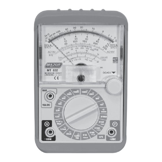
3. METER DESCRIPTION 1. Continuity Indicator 2. Reading Panel 3. Zero Corrector 4. 0Ω Adjusting Knob 5. Output Terminal (Series Condenser) 6. Function Switch 7. Measuring Terminal (-)/COM (COMMON) 8. Measuring Terminal(+) 9. Plastic Protection Cover 4. OPERATION WARNING: 1. Before using this instrument, please adjust the ZERO by Zero Corrector. -
Page 8: Resistance Test
4.1. RESISTANCE TEST 1. Set the function switch to the highest Ω position. 2. Insert the test leads into COM (Black lead) and "+" socket (Red lead) 3. Short the test leads and turn 0Ω adjusting knob to set the pointer to zero position. 4. -
Page 9: Acv Test
4.4. ACV TEST 1. Set the function switch to the highest ACV position. 2. Insert the test leads into COM (Black lead) and "+" socket (Red lead) 3. Connect the test leads to the circuit being tested, regardless of the polarities. (Fig.03) 4. -
Page 10: Ieco (Leakage Current) Test
4.8. Iceo (LEAKAGE CURRENT) TEST 1. Insert the test leads into COM (Black lead) and "+" socket (Red lead). 2. Set the function switch to X10 (15mA) for small size transistor, or to X1 (150mA) for big size transistor. 3. Short the test leads and turn on adjusting knob to set the pointer to the zero position. - Page 12 MAJOR TECH (PTY) LTD South Africa Australia www.major-tech.com www.majortech.com.au sales@major-tech.com info@majortech.com.au...
Need help?
Do you have a question about the MT832 and is the answer not in the manual?
Questions and answers