Advertisement
Quick Links
Advertisement

Related Manuals for Major tech MTC50


Summary of Contents for Major tech MTC50
- Page 1 Instruction Manual MTC50 2-in-1 LAN Tester & Multimeter...
-
Page 2: Table Of Contents
Contents Introduction..............3 Features..............3 Safety Precautions…………………………………….4 Meter Description.............5 Electrical Specification..........6 Operation……………………………………..………..8 Multi-Network Modular Cable Tester………………11... -
Page 3: Introduction
Introduction The 2-in-1 LAN Tester & Multimeter is an innovative tester that allows the user to easily measure DC/AC Voltage and Current, Resistance, Continuity, diode and verify the cable continuity; open short and cross-connect. The included remote terminator allows the user to test installed cable either at a wall jack or a patch panel adding up to value and convenience. -
Page 4: Safety Precautions
Safety International Safety Symbols This symbol, adjacent to another symbol or terminal, indicates the user must refer to the manual for further information. This symbol, adjacent to a terminal, indicates that, under normal use, hazardous voltages may be present. Double insulation Safety Precautions Improper use of this meter can cause damage, shock, injury or death. -
Page 5: Meter Description
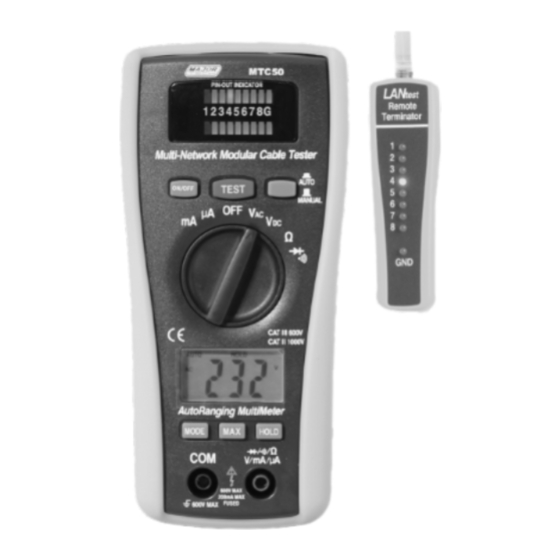
Meter Description LAN Tester part Description: Remote terminator with LED display for receiving end Jack RJ45 LAN-connector Jack RJ45 Jack RJ45 Led display for sourcing end (Jack 1) & Led display for receiving end (Jack 2) Test switch for auto scan LAN tester Power switch Test switch for manual scan 10. -
Page 6: Electrical Specification
11. 3 1/2 Digit (2000 count) LCD display for DMM functions 12. MODE button 13. MAX Hold button 14. Data Hold button 15. COM input jack 16. V,Ω,uA,mA input jack 17. Battery Cover Specifications Electrical Specifications Function Range Accuracy DC Voltage 200mV, ±(0.5% rdg + 3d) 2.000V, 20.00V, ±(1.0% rdg + 3d) - Page 7 Max input voltage 600V AC/DC Diode Test Test current 1mA max., open circuit voltage of 1.5V typical Continuity Check Audible signal if the resistance is <150Ω Display 2000 count 3 -1/2 digit LCD Over range indication LCD displays “OL” Polarity Minus (-) sign for negative polarity.
-
Page 8: Operation
Operation AC/DC VOLTAGE MEASUREMENTS CAUTION: Do not measure AC/ DC voltages if a motor on the circuit is being switched ON or OFF. Large voltage surges may occur that can damage the meter. Insert the black test lead into the negative COM terminal and the red test lead into the positive V terminal. - Page 9 RESISTANCE MEASUREMENT WARNING: To avoid electric shock, disconnect power to the unit under test and discharge all capacitors before taking any resistance measurements. Remove the batteries and unplug the line cords. 1. Set the function switch to the Ω position. 2.
- Page 10 typically indicate 0.400 to 0.700V. Reverse voltage will indicate “OL”. Shorted devices will indicate near 0V and an open device will indicate “OL” in both polarities MAX Hold button To hold the highest reading on the LCD Press the MAX hold button. The meter reading will not change as readings change Press the MAX hold button again to return to normal operation.
-
Page 11: Multi-Network Modular Cable Tester
REPLACING THE FUSES WARNING: To avoid electric shock, disconnect the test leads from any source of voltage before removing the fuse cover. Disconnect the test leads from the meter. Remove the protective rubber holster. Remove the battery cover (two “B” screws) and the battery. - Page 12 RJ45 jack on the master unit marked with a ' 回 ' and the other end of the cable into the remaining receiving RJ45 jack. Slide power switch on. The upper row of LEDs will start to scan in sequence if the Auto/Manual button is set on "Auto"...
- Page 13 As Coaxial cable has only two wires, we suggest you read the result of the LED scan using Manual mode. Remote Test Plug one end of the tested cable to the transmitting RJ45 jack on the master unit marked with a ' ' and plug the other end into the remote terminator.
Need help?
Do you have a question about the MTC50 and is the answer not in the manual?
Questions and answers