Advertisement
Quick Links
Advertisement

Related Manuals for Major tech MT1005


Summary of Contents for Major tech MT1005
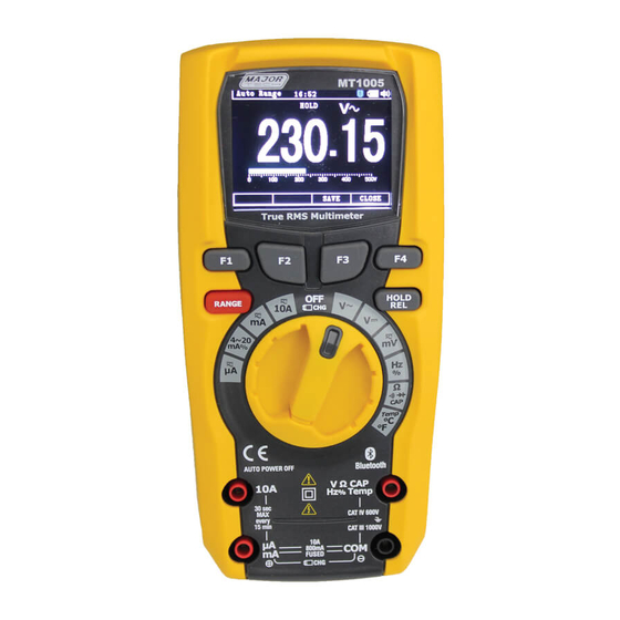
- Page 1 MT1005 True RMS Digital Multimeter...
-
Page 2: Table Of Contents
Contents Introduction..........4 Safety............4 Safety Instructions........8 Feature............8 Measure Function........11 Default Display...........19 Setup Options..........24 Specifications..........30... -
Page 3: Introduction
INTRODUCTION Professional True RMS Industrial Digital Multimeter and TFT color LCD display, providing fast A/D converting sampling time, high accuracy, built-in datalogging and Trend Capture features. It can trace any interruption problems of the equipment and watch on without person. It is easy to find and solve the problems of the production equipment, providing Bluetooth technology and memory the datasheets. - Page 4 PER IEC1010 OVERVOLTAGE INSTALLATION CATEGORY OVERVOLTAGE CATEGORY I Equipment of OVERVOLTAGE CATEGORY I is equipment for connection to circuits in which measures are taken to limit the transient overvoltages to an appropriate low level. Note: Examples include protected electronic circuits. OVERVOLTAGE CATEGORY II Equipment of OVERVOLTAGE CATEGORY II is energy-consuming equipment to be supplied from the fixed installation.
-
Page 5: Safety Instructions
Safety Instructions This meter has been designed for safe use, but must be operated with caution. The rules listed below must be carefully followed for safe operation. NEVER apply voltage or current to the meter that exceeds the specified maximum: Input Protection Limits Function Maximum Input... -
Page 6: Feature
Feature Understanding the Push Buttons The 6 push buttons on the front of the Meter activate features that augment the function selected using the rotary switch, navigate menus or control power to Meter circuits. F1 button, Default switch to Graph measure. F2 button, Default modes related to the rotary switch function. - Page 7 Understanding the Display Labels on the LCD display indicate the function of the button just below the displayed label. Analog bargraph display of the input signal. Minus sign Indicates a negative reading. Displays measurement information about the input signal. Indicates the range the Meter is in and the ranging mode (auto or manual) Indicates the time set in the internal clock.
- Page 8 Understanding the Rotary Switch Select a primary measurement function by positioning the rotary switch to one of the icons around its perimeter. For each function, the Meter presents a standard display for that function (range, measurement units, and modifiers). Button choices made in one function do not carry over into another function.
-
Page 9: Measure Function
Measure Function AC Voltage Measurements WARNING: Risk of Electrocution. The probe tips may not be long enough to contact the live parts inside some 240V outlets for appliances because the contacts are recessed deep inside the outlets. As a result, the reading may show 0V when the outlet actually has voltage present. - Page 10 DC Voltage Measurements CAUTION: Do not measure DC voltages if a motor on the circuit is being switched ON or OFF. Large voltage surges may occur that can damage the meter. Set the function switch to the yellow VDC position. Insert the black test lead banana plug into the negative COM jack.
- Page 11 mV Voltage Measurements CAUTION: Do not measure mV voltages if a motor on the circuit is being switched ON or OFF. Large voltage surges may occur that can damage the meter. Set the function switch to the yellow mV position. Press the MODE key.
- Page 12 Frequency Measurements Set the function switch to the yellow Hz% position. Insert the black test lead banana plug into the negative COM jack. Insert the red test lead banana plug into the positive V jack. Read the Frequency in the display. Resistance Measurements To avoid electric shock, disconnect power to the unit under test and discharge all capacitors...
- Page 13 Continuity Check WARNING: To avoid electric shock, disconnect power to the unit under test and discharge all capacitors before taking any resistance measurements. Remove the batteries and unplug the line cords. Set the function switch to the yellow Ω CAP position.
- Page 14 Capacitance Measurements WARNING: To avoid electric shock, disconnect power to the unit under test and discharge all capacitors before taking any capacitance measurements. Remove the batteries and unplug the line cords. Set the rotary function switch to the yellow Ω CAP position.
- Page 15 DC Current Measurements CAUTION: Do not make 20A current measurements for longer than 30 seconds. Exceeding 30 seconds may cause damage to the meter and/or the test leads. Insert the black test lead banana plug into the negative COM jack. For current measurements up to 5000µA DC, set the function switch to the yellow µA position and insert...
- Page 16 AC Current Measurements CAUTION: Do not make 10A current measurements for longer than 30 seconds. Exceeding 30 seconds may cause damage to the meter and/or the test leads. Insert the black test lead banana plug into the negative COM jack. For current measurements up to 5000µA AC, set the function switch to the yellow µA position...
-
Page 17: Default Display
Default Display Graph Measure Press Graph (F1) key, the meter will switch to Graph measure. Press the START key. Press the FAST or SLOW key to adjust the sampling rate. Press the CANCEL key to exit Graph and return to normal measurement mode Press the STOP key. - Page 18 Press the SAVE key to save the Graph. Press the BACK key to return. Capturing Minimum and Maximum Values To activate the MAX/MIN mode, Press MIN/MAX(F4) key, at the measurement mode. As shown in the Figure, the Meter displays at the top of the measurement page, the MAX/MIN start date and the amount of time at the bottom of the page.
- Page 19 Capturing Peak Values To activate the peak mode, at AC measure MIN/MAX mode , Press the PMAX(F4) button. Relative Values To activate the relative mode, Press the HOLD/REL button for more than 1 second. Hold Mode To freeze the display for any function, press the HOLD button.
- Page 20 Save Function Press the SAVE(F3) key to enter the save menu Storing Individual Measurement Data For common measurement functions, a snapshot of the screen data is saved by pressing the SAVE key. Then press the DOWN(F3) key to save the selected item, press the ENTER(F1) key.
- Page 21 Press the « and » keys to move cursor. Recording Measurement Data Press the SAVE key. Then press the DOWN (F3) key to Record the selected item, press the ENTER(F1) key. Press the START key to start recording. The recording session will continue until the allocated memory is used, the batteries expire, the rotary switch is moved.
-
Page 22: Setup Options
Press the key to increase Graph » resolution. Press the keys to move cursor. Info Viewing data stored in the Meter's memory is performed through the SAVE menu. Press the DOWN (F3) key. Position the menu selector next to the menu item labeled INFO and press the ENTER(F1) key. - Page 23 Meter Info The Meter Info selection lists the serial number and firmware version. Open the setup menu. Position the menu selector next to the menu item labeled METER INFO and press the ENTER key. Setting Format Open the setup menu. Position the menu selector next to the menu item labeled FORMAT and press the ENTER key.
- Page 24 Auto Power Off Open the setup menu. Position the menu selector next to the menu item labeled DISPLAY and press the ENTER key. Then Position the menu selector next to the menu item labeled POWER OFF and press the EDIT key.
- Page 25 Replacing the Batteries Refer to Figure and replace the batteries as follows: Turn the Meter off and remove the test leads from the terminals. Remove the battery door assembly by using a flat end screwdriver to turn the battery door screw one-half turn counterclockwise. Replace the battery with 7.4V charge battery.
- Page 26 Li-ion Battery Charge Set the function switch to the OFF/CHG position. Insert the socket into the Meter Input port, and connect the Adapter to the switch socket. Then Insert the Adapter into a Power socket. A charge symbol will be displayed on the TFT color LCD display. Enclosure Double molded Shock (Drop Test)
- Page 27 AC True RMS The term stands for "Root-Mean-Square," which represents the method of calculation of the voltage or current value. Average responding multimeters are calibrated to read correctly only on sine waves and they will read inaccurately on non-sine wave or distorted signals. True RMS meters read accurately on either type of signal.
-
Page 28: Specifications
Specifications Range <20kHz[1] 50/60Hz Resolution <1kHz <5kHz 500mV 0.01mV ±0.5% ±1.0% ±3.0% ±5.5% 0.0001V 0.001V Voltage ±3.5% Unspecified 500V 0.01V ±1.5% 1000V 0.1V Unspecified Unspecified [1] upper 10% of range Range Accuracy Function Resolution DC Voltage 500mV[1] (0.1% + 5 digits) 0.01mV (0.05% + 5 digits) 0.0001V... - Page 29 Range Accuracy Function Resolution Temp -200 to 1350°C 0.1°C ± (1.0% reading + 3.0°C) (Type-K) ± (1.0% reading + 5.4°C) (probe accuracy not included) 1. Does not include thermocouple probe error. 2. Accuracy specification assumes ambient temperature stable to ±1°C. 3.
- Page 30 Function Range Resolution Accuracy Frequency 50Hz 0.001Hz ±(0.01% + 5) (electronic) 500Hz 0.01Hz ±(0.01% + 5) 5kHz 0.0001kHz ±(0.01% + 5) 50kHz 0.001kHz ±(0.01% + 5) 500kHz 0.01kHz ±(0.01% + 5) ±(0.01% + 5) 0.0001MHz 5MHz unspecified 10MHz 0.001MHz Sensitivity: 2V RMS min. @ 20% to 80% duty cycle and <100kHz;...
- Page 32 MAJOR TECH (PTY) LTD T9 Industrial Village, Sam Green Road, Telephone: +27 11 8 2 7 5500 Sales Facsimile: +27 11 822 2806 Tunney Ext. 9, Elandsfontein South Africa Admin Facsimile: +27 11 822 1411 E-mail: sales@major-tech.com P .O. Box 888, Isando, 1600, South Africa www.major-tech.com...
Need help?
Do you have a question about the MT1005 and is the answer not in the manual?
Questions and answers