Table of Contents
Advertisement
Quick Links
Advertisement
Table of Contents

Related Manuals for Major tech MT1887 IV


Summary of Contents for Major tech MT1887 IV
- Page 1 INSTRUCTION MANUAL MT1887 1500V DC MULTIMETER...
-
Page 3: Table Of Contents
Contents Page no 1. Introduction..................4 2. Safety Symbols..................4 3. Safety Instructions................5 4. Controls and Jacks................6 5. Symbols used on LCD................7 6. Operating Instructions................7 6.1. DC Voltage Measurements............8 6.2. AC Voltage (Frequency, Duty Cycle) Measurements......8 6.3. DC Current Measurements............9 6.4. AC Current (Frequency, Duty Cycle) Measurements.......10 6.5. -
Page 4: Introduction
1. INTRODUCTION This meter measures AC/DC Voltage, AC/DC Current, Resistance, Capacitance, Frequency (electrical & electronic), Duty Cycle, Diode Test, and Continuity plus Thermocouple Temperature. It features a waterproof, rugged design for heavy duty use. Proper use and care of this meter will provide many years of reliable service. -
Page 5: Safety Instructions
Note – Examples include switches in the fixed installation and some equipment for industrial use with permanent connection to the fixed installation. OVERVOLTAGE CATEGORY IV Equipment of OVERVOLTAGE CATEGORY IV is for use at the origin of the installation. Note – Examples include electricity meters and primary over-current protection equipment 3. -
Page 6: Controls And Jacks
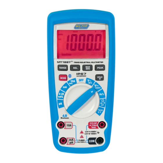
4. CONTROLS AND JACKS 1 - 40,000 count LCD display 7 - COM input jack 2 - REL button 8 - Positive input jack 3 - RANGE button 9 - HOLD and (Backlight) button 4 - MODE/Bluetooth button 10 - PEAK button 5 - Function switch 11 - MAX/MIN button 6 - mA, μA and 10A input jacks... -
Page 7: Symbols Used On Lcd
5. SYMBOLS USED ON LCD µ Volts micro (10 ) Amperes milli (10 ) Alternating current kilo (10 ) Direct current mega (10 ) Minus sign Overload Ω Ohms Auto Power Off Continuity Low battery Diode test Autoranging AUTO Farads (capacitance) Display hold HOLD MAX/MIN/AVG... -
Page 8: Dc Voltage Measurements
6.1. DC VOLTAGE MEASUREMENTS CAUTION: Do not measure DC voltages if a motor on the circuit is being switched ON or OFF. Large voltage surges may occur that can damage the meter. 1. Set the function switch to the "VDC" position. 2. -
Page 9: Dc Current Measurements
6.3. DC CURRENT MEASUREMENTS CAUTION: Do not make 20A current measurements for longer than 30 seconds. Exceeding 30 seconds may cause damage to the meter and/or the test leads. 1. Insert the black test lead banana plug into the negative COM jack. 2. -
Page 10: Ac Current (Frequency, Duty Cycle) Measurements
6.4. AC CURRENT (FREQUENCY, DUTY CYCLE) MEASUREMENTS CAUTION: Do not make 20A current measurements for longer than 30 seconds. Exceeding 30 seconds may cause damage to the meter and/or the test leads. 1. Insert the black test lead banana plug into the negative COM jack. -
Page 11: Resistance Measurements
6.5. RESISTANCE MEASUREMENTS WARNING: To avoid electric shock, disconnect power to the unit under test and discharge all capacitors before taking any resistance measurements. Remove the batteries and unplug the line cords. 1. Set the function switch to the Ω CAP position. -
Page 12: Diode Test
6.7. DIODE TEST 1. Set the function switch to the Ω CAP position. 2. Insert the black test lead banana plug into the negative COM jack and the red test lead banana plug into the positive V jack. 3. Press the MODE button to indicate " "... -
Page 13: Frequency (Frequency, Duty Cycle) Measurement (Electronic)
6.10. FREQUENCY (DUTY CYCLE) MEASUREMENTS (ELECTRONIC) 1. Set the function switch to the Hz/% position. 2. Insert the black lead banana plug into the negative COM jack and the red test lead banana plug into the positive Hz jack. 3. Touch the test probe tips to the circuit under test. -
Page 14: Auto Ranging/Manual Range Selection
6.13. AUTO RANGING/MANUAL RANGE SELECTION When the meter is first turned on, it automatically goes into Auto Ranging. This automatically selects the best range for the measurements being made and is generally the best mode for most measurements. For measurement situations requiring that a range be manually selected, perform the following: 1. -
Page 15: Hold
6.17. HOLD The hold function freezes the reading in the display. Press the HOLD key momentarily to activate or to exit the HOLD function. 6.18. PEAK HOLD The Peak Hold function captures the peak AC or DC voltage or current. The meter can capture negative or positive peaks as fast as 1 millisecond in duration. -
Page 16: Auto Power Off
6.20. AUTO POWER OFF The auto off feature will turn the meter off after 15 minutes. To disable the auto power off feature, hold down the MODE button and turn the meter on. "APO d" will appear in the display. Turn the meter off and then on again to re-enable the auto power off feature. -
Page 17: Battery Installation
7.1. BATTERY INSTALLATION WARNING: To avoid electric shock, disconnect the test leads from any source of voltage before removing the battery cover. 1. Turn power off and disconnect the test leads from the meter. 2. Open the rear battery cover by removing two screws (B) using a Phillips head screwdriver. -
Page 18: Specifications
8. SPECIFICATIONS 8.1. DC VOLTAGE Range Resolution Accuracy 400.0mV 0.1mV ± 0.2% of reading ± 15digits 0.0001V ±0.1 of reading ± 6 digits 0.001V 400V 0.01V 1500V 1.0V ±0.1% of reading ± 6 digits 8.2. AC VOLTAGE 50 to 1000Hz Range Resolution Accuracy... -
Page 19: Resistance
8.5. RESISTANCE Range Resolution Accuracy 400Ω 0.01Ω ±0.5% of reading ± 15 digits 4kΩ 0.0001KΩ 40kΩ 0.001KΩ ±0.5% of reading ± 8 digits 400KΩ 0.01KΩ 4MΩ 0.001MΩ ±2.0% of reading ± 10 digits 40MΩ 0.01MΩ 8.6. CAPACITANCE Range Resolution Accuracy 40nF 0.01nF ±2.5% of reading ±... -
Page 20: Duty Cycle
8.9. DUTY CYCLE Range Resolution Accuracy 5.0 to 95.0% 0.01% ±(1.2% reading + 2 digits) Pulse frequency range: 40Hz - 10kHz, Pulse amplitude:±5V (100μs -100ms) 8.10. TEMPERATURE - (TYPE-K) Range Resolution Accuracy -50°C to 1000°C 1 °C ±1.0% of reading + 2.5°C -58 to 1832°F 1°F ±1.0% of reading + 4.5°F... -
Page 21: General Specifications
8.12. GENERAL SPECIFICATIONS Range Function Enclosure Double molded, waterproof Shock (Drop Test) 6.5 feet (2 meters) Diode Test Test current of 1.5mA maximum, open circuit voltage 3.2V DC typical Continuity Check Audible signal will sound if the resistance is less than 35Ω... - Page 22 8.12. GENERAL SPECIFICATIONS Cont. Function Range Operating Temperature 5ºC to 40ºC (41ºF to 104ºF) Storage Temperature -20ºC to 60ºC (-4ºF to 140ºF) Operating Humidity Max 80% Storage Humidity <80% up to 31ºC decreasing linearly to 50% at 40ºC Operating Altitude 2000 meters maximum.
- Page 24 MAJOR TECH (PTY) LTD South Africa Australia www.major-tech.com www.majortech.com.au sales@major-tech.com info@majortech.com.au...
Need help?
Do you have a question about the MT1887 IV and is the answer not in the manual?
Questions and answers