Table of Contents
Advertisement
Quick Links
Advertisement
Table of Contents

Subscribe to Our Youtube Channel
Related Manuals for Major tech MT24


Summary of Contents for Major tech MT24
- Page 1 INSTRUCTION MANUAL MT24 1000V AC/DC MULTIMETER...
-
Page 3: Table Of Contents
Contents Page no 1. Introduction ..................4 2. Safety Symbols .................4 3. Controls and Jacks ................5 4. Symbols and Annciators ..............5 5. Specifications ................6 5.1. DC Voltage ................6 5.2. AC Voltage ................7 5.3. DC Current ................7 5.4. AC Current ................7 5.5. Resistance ................7 5.6. -
Page 4: Introduction
1. INTRODUCTION The following safety information must be observed to insure maximum personal safety during the operation at this meter: Ÿ Do not use the meter if the meter or test leads look damaged, or if you suspect that the meter is not operating properly. Ÿ... -
Page 5: Controls And Jacks
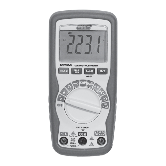
3. CONTROLS AND JACKS 1 - 6000 count LCD with symbolic 5 - Positive input jack signs 6 - HOLD/Backlight Button 2 - Function switch 7 - Max/Min Button 3 - 10A (positive) input jack for 8 - Range/Diode Button 10A DC or AC measurements 9 - Hz/Duty Button 4 - COM (negative) input jack... -
Page 6: Specifications
5. SPECIFICATIONS Range Function The instrument complies with: EN61010-1. Insulation: Class2, Double insulation. Overvoltage category: CATIII 600V, CATII 1000V. Display: 6000 counts LCD display with function indication. Polarity: Automatic, (-) negative polarity indication Overrange: “OL” mark indication. Low battery indication: The “BAT”... -
Page 7: Ac Voltage
5.2. AC VOLTAGE Range Resolution Accuracy 6.000V +1.2% of rdg + 3 dgts 60.00V 10mV +1.5% of rdg + 3 dgts 600.0V 100mV 1000V +2.0% of rdg + 4 dgts Input Impedance: 7.8MΩ. Frequency Range: 50 to 60Hz Maximum Input: 1000V DC or 1000V AC RMS. 5.3. -
Page 8: Capacitance (Auto-Ranging)
5.6. CAPACITANCE (Auto-ranging) Range Resolution Accuracy 40.00nF 10pF +5.0% of rdg + 50 dgts 400.0nF 0.1nF 40.00uF 10nF +3.0% of rdg + 5 dgts 4.000uF 400.0uF 0.1uF +5.0% of rdg + 5 dgts 4000uF +5.0% of rdg + 5 dgts Maximum Input: 600V DC or 600V AC RMS. -
Page 9: Diode Test
5.10. DIODE TEST Range Resolution Accuracy 0.3mA 1 mV +10% of rdg + 5 dgts typical Open circuit voltage: 1.5V DC typical Overload protection: 600V DC or AC RMS. 5.11. AUDIBLE CONTINUITY Audible threshold: Less than 100Ω; Test current: <0.3mA Overload protection: 600V DC or AC RMS. -
Page 10: Min/Max
6.2. MAX/MIN NOTE: When using the MAX/MIN function in Auto ranging mode, the meter will “lock” into the range that is displayed on the LCD when MAX/MIN is activated. If a MAX/Min reading exceeds that range, an “OL” will be displayed. Select the desired range BEFORE entering MAX/MIN mode. -
Page 11: Ac Voltage Measurements
6.7. AC VOLTAGE MEASUREMENTS WARNING: Risk of Electrocution. The probe tips may not be long enough to contact the live parts inside some 240V outlets for appliances because the contacts are recessed deep in the outlets. As a result, the reading may show 0 volts when the outlet actually has voltage on it. -
Page 12: Ac Current Measurements
6.9. AC CURRENT MEASUREMENTS WARNING: To avoid electric shock, do not measure AC current on any circuit whose voltage exceeds 250V AC. CAUTION: Do not make current measurements on the 10A scale for longer than 30 seconds. Exceeding 30 seconds may cause damage to the meter and/or the test leads. -
Page 13: Diode Test
Touch the test probe tips to the circuit or wire you wish to check. If the resistance is less than approximately 100Ω, the audible signal will sound. The display will also show the actual resistance. 6.12. DIODE TEST WARNING: To avoid electric shock, do not test any diode that has voltage on it. -
Page 14: Temperature Measurements
6.15. TEMPERATURE MEASUREMENTS WARNING: To avoid electric shock, disconnect both test probes from any source of voltage before making a temperature measurement. If you wish to measure temperature in °F, set the function switch to the °F range. If you wish to measure temperature in °C, set the function switch to the °C range. -
Page 15: Replacing The Fuses
Insert the battery into battery holder, observing the correct polarity. Put the battery cover back in place. Secure with the two screws. WARNING: To avoid electric shock, do not operate the meter until the battery door is in place and fastened securely. NOTE: If your meter does not work properly, check the fuses and battery to make sure that they are still good and that they are properly inserted. - Page 16 MAJOR TECH (PTY) LTD South Africa Australia www.major-tech.com www.majortech.com.au sales@major-tech.com info@majortech.com.au...
Need help?
Do you have a question about the MT24 and is the answer not in the manual?
Questions and answers