Table of Contents
Advertisement
Quick Links
Advertisement
Table of Contents

Related Manuals for Major tech MT1882


Summary of Contents for Major tech MT1882
- Page 1 INSTRUCTION MANUAL MT1882 1000V AC/DC TRMS MULTIMETER...
-
Page 3: Table Of Contents
Contents Page no 1. Introduction ..................4 2. Safety Symbols .................4 3. Safety Instructions ................5 4. Controls and Jacks ................6 5. Symbols and Annunciators ..............7 6. Operating Instructions ...............7 6.1. DC Voltage Measurements ............8 6.2. AC Voltage (Frequency, Duty Cycle) Measurement .......8 6.3. -
Page 4: Introduction
1. INTRODUCTION This meter measures AC/DC Voltage, AC/DC Current, Resistance, Capacitance, Frequency (electrical & electronic), Duty Cycle, Diode Test, and Continuity plus Thermocouple Temperature. Proper use and care of this meter will provide many years of reliable service. 2. SAFETY SYMBOLS This symbol adjacent to another symbol, terminal or operating device indicates that the operator must refer to an explanation in the Operating Instructions to avoid personal... -
Page 5: Safety Instructions
Note – Examples include switches in the fixed installation and some equipment for industrial use with permanent connection to the fixed installation. OVERVOLTAGE CATEGORY IV Equipment of OVERVOLTAGE CATEGORY IV is for use at the origin of the installation. Note – Examples include electricity meters and primary over-current protection equipment 3. -
Page 6: Controls And Jacks
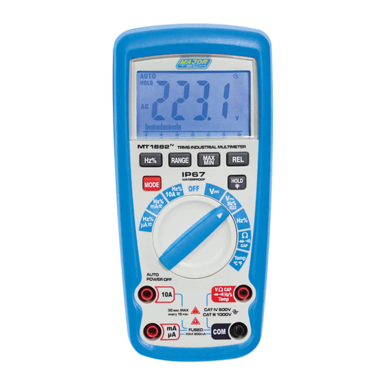
4. CONTROLS AND JACKS 1 - 6,000 count LCD display 7 - COM input jack 2 - Hz% button 8 - Positive input jack 3 - RANGE button Backlight and Hold button 4 - MODE button 10 - MAX/MIN button 5 - Function switch 11 - REL button 6 - mA, μA and 10A input jacks... -
Page 7: Symbols And Annunciators
5. SYMBOLS AND ANNUNCIATORS Continuity Relative Diode test Alternating current Battery status Direct current nano (10- ) (capacitance) Maximum µ micro (10- ) (amps, cap) Auto Range Timing symbol AUTO Backlight Bargraph milli (10- ) (volts, amps) Volts Amps Frequency Conversion Measure kilo (10 ) (ohms) Auto ranging AUTO... -
Page 8: Dc Voltage Measurements
6.1. DC VOLTAGE MEASUREMENTS CAUTION: Do not measure DC voltages if a motor on the circuit is being switched ON or OFF. Large voltage surges may occur that can damage the meter. 1. Set the function switch to the "DC" position. 2. -
Page 9: Dc Current Measurement
6.3. DC CURRENT MEASUREMENT CAUTION: Do not make 10A current measurements for longer than 30 seconds. Exceeding 30 seconds may cause damage to the meter and/or the test leads. 1. Insert the black test lead banana plug into the input jack. 2. -
Page 10: Resistance Measurements
Connect the black test probe tip and the red test probe tip in series to the circuit whose current you want to measure. 8. Apply power to the circuit, read the current on the display. 9. Press the Hz/% Button to indicate "Hz", read the frequency on the display. -
Page 11: Diode Test
6.7. DIODE TEST 1. Set the function switch to the Ω CAP position. 2. Insert the black test lead banana plug into the negative COM jack and the red test lead banana plug into the positive V jack. 3. Press the MODE button to indicate " "... -
Page 12: Frequency Measurement
6.10. FREQUENCY MEASUREMENT 1. Set the function switch to the Hz/Duty position. 2. Insert the black test lead banana plug into the negative jack (COM) and the red test lead banana plug into the positive jack (F). 3. Touch the test probe tips to the circuit under test. 4. -
Page 13: Min/Max Button
6.14. MIN/MAX BUTTON The meter displays the maximum or minimum value of input in the Max/Min mode. When Max/Min is pressed for the first time, the meter displays the maximum value. The meter displays the minimum value when it is pressed again. When Max/Min is pressed for the third time, the meter displays current value. -
Page 14: Battery Installation
7.1. BATTERY INSTALLATION WARNING: To avoid electric shock, disconnect the test leads from any source of voltage before removing the battery cover. 1. Turn power off and disconnect the test leads from the meter. 2. Open the rear battery cover by removing two screws (B) using a Phillips head screwdriver. -
Page 15: Ac Voltage (Vfd)
8.3. AC VOLTAGE (VFD) Range Resolution Accuracy 50.0V to 600.0V 0.1V ±4.0%of reading ± 9digits Input Impedance: approx 10MΩ. AC Response: 50 Hz to 400Hz Maximum Input: 600V DC or 600V AC RMS. 8.4. DC CURRENT (AUTO-RANGING) Range Resolution Accuracy 600.0uA 0.1uA 6000uA... -
Page 16: Resistance (Auto-Ranging)
8.6. RESISTANCE [Ω] (AUTO-RANGING) Range Resolution Accuracy 600.0Ω 0.1Ω ±1.0% of reading ± 2 digits 6.000kΩ 0.001kΩ 60.00kΩ 0.01kΩ ±0.8% of reading ± 2 digits 600.0kΩ 0.1kΩ 6.000MΩ 0.001MΩ ±1.2% of reading ±8digits 60.00MΩ 0.01MΩ Input Protection: 250V DC or 250V AC RMS. 8.7. -
Page 17: Frequency (Electrical)
8.9. FREQUENCY (ELECTRICAL) Range Resolution Accuracy 10.00~1KHz 0.01Hz ±(1.5% reading) Sensitivity: ACmV Range (≥100mV),ACV Range (≥6% Range), 6000μA/600.0mA/10.00A Range (≥6% Range), 600.0μA/60.00mA/6.000A (≥60% Range) 8.10. DUTY CYCLE Range Resolution Accuracy 0.1%~99.9% 0.1% ±1.2% of reading ±2 dgts Pulse width: >100us, <100ms; Frequency width: 5Hz –... -
Page 18: Audible Continuity
8.13. AUDIBLE CONTINUITY Range Function Enclosure Double molded, waterproof Shock (Drop Test) 6.5 feet (2 meters) Diode Test Test current of 0.9mA maximum, open circuit voltage 3.2V DC typical Continuity Check Audible signal will sound if the resistance is less than 50Ω... -
Page 19: Non-Contact Voltage (Ncv)
8.14. NON-CONTACT VOLTAGE (NCV) Function Range Auto Power Off 15 minutes (approximately) with disable feature Polarity Automatic (no indication for positive); Minus (-) sign for negative Measurement Rate 3 times per second, nominal Low Battery Indication “ “ is displayed if battery voltage drops below operating voltage Battery One 9 volt (NEDA 1604) battery... - Page 20 MAJOR TECH (PTY) LTD South Africa Australia www.major-tech.com www.majortech.com.au sales@major-tech.com info@majortech.com.au...
Need help?
Do you have a question about the MT1882 and is the answer not in the manual?
Questions and answers