Table of Contents
Advertisement
Quick Links
Advertisement
Table of Contents

Related Manuals for Major tech MT565


Summary of Contents for Major tech MT565
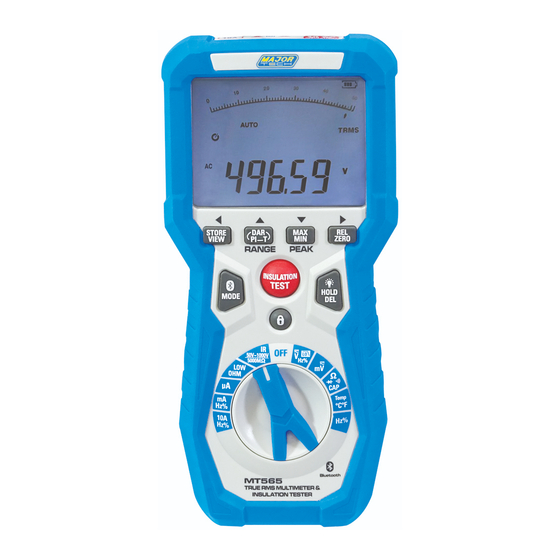
- Page 1 INSTRUCTION MANUAL MT565 INSULATION TESTER & BLUETOOTH MULTIMETER...
-
Page 3: Table Of Contents
Contents Page no 1. Introduction..................4 2. Safety Symbols...................4 3. Safety Instructions................5 4. Controls and Jacks................6 5. Symbols and Annunciators..............7 6. Operating Instructions.................8 6.1. DC Voltage Measurements............8 6.2. AC Voltage (Frequency, Duty Cycle) Measurement......9 6.3. MV Voltage Measurements............9 6.4. DC Current Measurements............10 6.5. -
Page 4: Introduction
1. INTRODUCTION This meter measures AC/DC Voltage, AC/DC Current, Resistance, Capacitance, Frequency (electrical & electronic), Duty Cycle, Diode Test, Insulation Test, and Continuity plus Thermocouple Temperature. It can store and recall data. It features a waterproof, rugged design for heavy duty use. -
Page 5: Safety Instructions
Equipment of OVERVOLTAGE CATEGORY III is equipment in fixed installations. Note – Examples include switches in the fixed installation and some equipment for industrial use with permanent connection to the fixed installation. OVERVOLTAGE CATEGORY IV Equipment of OVERVOLTAGE CATEGORY IV is for use at the origin of the installation. -
Page 6: Controls And Jacks
If the equipment is used in a manner not specified by the manufacturer, the protection provided by the equipment may be impaired. 4. CONTROLS AND JACKS 1 - mA, μA, temp,INS and Rlow 8 - INSULATION LOCK button input jacks 9 - COM input jack 2 - 10A input jacks 10 - Input Terminal to operate the... -
Page 7: Symbols And Annunciators
5. SYMBOLS AND ANNUNCIATORS Continuity Low pass filtering Diode test Timing symbol Battery status Backlight nano (10- ) (capacitance) bargraph µ micro (10- ) (amps, cap) milli (10- ) (volts, amps) Amps kilo (10 ) (ohms) Farads (capacitance) mega (10 ) (ohms) Ω... -
Page 8: Operating Instructions
6. OPERATING INSTRUCTIONS WARNING: Risk of electrocution. High-voltage circuits, both AC and DC, are very dangerous and should be measured with great care. 1. ALWAYS turn the function switch to the OFF position when the meter is not in use. 2. -
Page 9: Ac Voltage (Frequency, Duty Cycle) Measurement
6.2. AC VOLTAGE (FREQUENCY, DUTY CYCLE) MEASUREMENT CAUTION: Do not measure AC voltages if a motor on the circuit is being switched ON or OFF. Large voltage surges may occur that can damage the meter. WARNING: Risk of Electrocution. The probe tips may not be long enough to contact the live parts inside some 240V outlets for appliances because the contacts are recessed deep in the outlets. -
Page 10: Dc Current Measurements
6.4. DC CURRENT MEASUREMENTS CAUTION: Do not make 20A current measurements for longer than 30 seconds. Exceeding 30 seconds may cause damage to the meter and/or the test leads. 1. Insert the black test lead banana plug into the negative COM jack. 2. -
Page 11: Ac Current (Frequency, Duty Cycle) Measurement
6.5. AC CURRENT (FREQUENCY, DUTY CYCLE) MEASUREMENTS CAUTION: Do not make 20A current measurements for longer than 30 seconds. Exceeding 30 seconds may cause damage to the meter and/or the test leads. 1. Insert the black test lead banana plug into the negative COM jack. -
Page 12: Resistance Measurements
6.6. RESISTANCE MEASUREMENTS WARNING: To avoid electric shock, disconnect power to the unit under test and discharge all capacitors before taking any resistance measurements. Remove the batteries and unplug the line cords. Ω 1. Set the function switch to the position. -
Page 13: Diode Test
6.8. DIODE TEST Ω 1. Set the function switch to the position. 2. Insert the black test lead banana plug into the negative COM jack and the red test lead banana plug into the positive Ω jack. 3. Press the MODE button to indicate “ ”... -
Page 14: Temperature Measurements
6.10. TEMPERATURE MEASUREMENTS 1. Set the function switch to the Temp position. 2. Insert the Temperature Probe into the input jacks, making sure to observe the correct polarity. 3. Press the MODE button to indicate “ºC” or “ºF” 4. Touch the Temperature Probe head to the part whose temperature you wish to measure. -
Page 15: Insulation Resistance Measurements
6.12. INSULATION RESISTANCE MEASUREMENTS 1. Set the rotary function switch to the INSULATION position ,and Press the RANGE button to chose one of the voltage which display on the left . 2. Connect two testing lines to the tested. 3. Push down and hold the “TEST” button to be test. If there is voltage (AC/DC) over 30V, the insulation test will not work. -
Page 16: Dar And Pi Insulation Tests
rigging by connecting one megohmmeter lead to each of them individually, leaving the other connected to the grounded motor housing. The above also applies to DC Generators. CABLES Disconnect the cable from the line. Also disconnect opposite end to avoid errors due to leakage from other equipment. -
Page 17: Mode/Bluetooth
DAR is selected, the lock function will be active. 4. Connect the two testing line to be tested. 5. When the PI OR DAR functional test is complete, the instrument will automatically exit the test and display the result on the left side of the LCD display. -
Page 18: Autoranging/Manual Range Selection
7. AUTORANGING/MANUAL RANGE SELECTION When the meter is first turned on, it automatically goes into AutoRanging. This automatically selects the best range for the measurements being made and is generally the best mode for most measurements. For measurement situations requiring that a range be manually selected, perform the following: 1. -
Page 19: Hold
7.4. HOLD The hold function freezes the reading in the display. Press the HOLD key momentarily to activate or to exit the HOLD function. 7.5. PEAK HOLD The Peak Hold function captures the peak voltage or current. The meter can capture negative or positive peaks as fast as 1 millisecond in duration. Press and hold for about two seconds the PEAK button, “PEAK”... -
Page 20: Maintenance
8. MAINTENANCE WARNING: To avoid electric shock, disconnect the test leads from any source of voltage before removing the back cover or the battery or fuse covers. WARNING: To avoid electric shock, do not operate your meter until the battery and fuse covers are in place and fastened securely. This MultiMeter is designed to provide years of dependable service, if the following care instructions are performed: 1. -
Page 21: Replacing The Fuses
8.2. REPLACING THE FUSES WARNING: To avoid electric shock, disconnect the test leads from any source of voltage before removing the meter cover. 1. Disconnect the test leads from the meter. 2. Remove the battery cover (two “B” screws) and the battery. 3. -
Page 22: Dc Current
9.3. DC CURRENT Range Resolution Accuracy 500µA 0.01µA 5000µA 0.1µA 50mA 0.001mA ±(1.0% reading + 3 digits) 500mA 0.01mA 0.001A 9.4. AC CURRENT Range Resolution Accuracy 500µA 0.01µA 5000µA 0.1µA 50mA 0.001mA ±(1.5% reading + 3digits) 500mA 0.01mA (50 to1000Hz) 0.001A All AC current ranges are specified from 5% of range to 100% of range 9.5. -
Page 23: Frequency (Electronic)
9.7. FREQUENCY (ELECTRONIC) Range Resolution Accuracy 50Hz 0.001Hz 500Hz 0.01Hz 5kHz 0.0001kHz 50kHz 0.001kHz ±(0.3% reading + 2 digits) 500kHz 0.01kHz 5MHz 0.0001MHz 50MHz 0.001MHz Sensitivity: 0.8V rms min. @ 20% to 80% duty cycle and <100kHz; 5Vrms min @ 20% to 80% duty cycle and >100kHz. 9.8. -
Page 24: Meg Ohms
9.11. MEG OHMS Terminal Range Resolution Accuracy Test Voltage Current 0.050~5.000MΩ 0.001MΩ ±(2%+10) (0%~ 5.000~50.00MΩ 0.01MΩ ±(3%+10) @load +20%) 50.00~500.0MΩ 0.1MΩ ±(4%+5) 50kΩ 500~2000MΩ 1MΩ ±(5%+5) 100V 0.100~5.000MΩ 0.001MΩ ±(2%+10) (0%~ 5.000~50.00MΩ 0.01MΩ ±(3%+10) @load +20%) 50.00~500.0MΩ 0.1MΩ ±(4%+5) 250kΩ 500~5000MΩ... -
Page 25: General Specifications
9.13. GENERAL SPECIFICATIONS Range Function Enclosure Double molded, waterproof IP65 Shock (Drop Test) 3.2 feet (1 meters) Diode Test Test current of 0.9mA maximum, open circuit voltage 2.8V DC typical Continuity Check Audible signal will sound if the resistance is less than 50Ω (approx.), test current <0.35mA PEAK Captures peaks >1ms... - Page 28 MAJOR TECH (PTY) LTD South Africa Australia www.major-tech.com www.majortech.com.au sales@major-tech.com info@majortech.com.au...
Need help?
Do you have a question about the MT565 and is the answer not in the manual?
Questions and answers