Advertisement
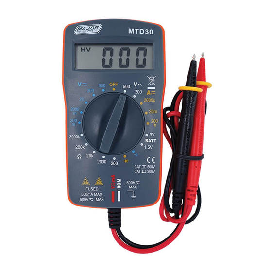
DIGITAL MULTIMETER
1. SAFETY INFORMATION
SAFETY SYMBOLS
Warning! Dangerous Voltage (Risk of electric shock).
Caution! Refer to the user's manual before using this Meter.
Double Insulation (Protection Class Ⅱ).
Alternating Current (AC).
Direct Current (DC).
Either DC or AC.
Ground (maximum permitted voltage between terminal and ground).
The symbol indicates separate collection for electrical and electronic equipment.
The RESPONSIBLE BODY shall be made aware that, if the instrument
is used in a manner not specified by the manufacturer, the protection
provided by the instrument may be impaired.
The finger or any part of your body shall not be beyond the barrier of
the test probe when measuring.
Individual protective equipment must be used if HAZARDOUS LIVE parts in the
installation where measurement is to be carried out could be ACCESSIBLE.
The following safety information must be observed to insure maximum personal safety
during the operation at this meter.
2000 COUNTS
Operation MANUAL
1
MTD30
Advertisement
Table of Contents

Related Manuals for Major tech MTD30


Summary of Contents for Major tech MTD30
- Page 1 MTD30 2000 COUNTS DIGITAL MULTIMETER OPERATION MANUAL 1. SAFETY INFORMATION SAFETY SYMBOLS Warning! Dangerous Voltage (Risk of electric shock). Caution! Refer to the user’s manual before using this Meter. Double Insulation (Protection Class Ⅱ). Alternating Current (AC). Direct Current (DC).
- Page 2 Do not operate the meter if the body of the meter or the test lead looks broken. Check the main function dial and make sure it is at the correct position before each measurement. When making current measurements ensure that the circuit is not “live” before opening it in order to connect the test leads.
- Page 3 ELECTRICAL SPECIFICATIONS Accuracies are ± ( % of reading + number in last digit ) at 23 ± 5°C ,≤75% RH. 2.2.1 DC Voltage Range Accuracy Resolution 200mV 0.1mV 2000mV ± ( 1.0%+2 ) 10mV 200V 100mV 500V ± ( 1.2%+2 ) Overload protection: 500V DC or AC rms Impedance: 1MΩ...
- Page 4 2.2.5 Diode and Audible continuity test Range Description Test condition Display read Forward DC current approximately approx. 10μA forward voltage Reversed DC voltage of diode approx. 1.8V Built-in buzzer Open circuit voltage sounds approx. 1.8V resistance is less than 50Ω Overload protection: F0.5A/600V fuse 2.2.6 Battery test Range...
- Page 5 Read the result from the LCD panel. Note: See DC voltage measurement note a)~d). DC Current Measurement Set the selector switch to desired “mA ” position. Remove power from the circuit under test and open the normal circuit path where the measurement is to be taken. Connect the meter in series with the circuit.
- Page 6 Note: Make sure the power is cut off and all capacitors need to be discharged under this measurement. Audible continuity Test Set the selector switch to desired “ ” position. Connect the test leads to two point of circuit, if the resistance is lower than approx.
- Page 7 box of the front case and lift the bottom case. Replace the old fuse with the same type and rating: 5×20mm F0.5A/600V fuse. Close the bottom case and the battery cover and fasten the screws. MAINTENANCE Before open the bottom case, never uses the meter before the bottom case is closed.
Need help?
Do you have a question about the MTD30 and is the answer not in the manual?
Questions and answers