Table of Contents
Advertisement
Quick Links
Advertisement
Table of Contents

Related Manuals for Major tech MT1887


Summary of Contents for Major tech MT1887
- Page 1 User's Guide True RMS Industrial Multimeter...
-
Page 2: Overvoltage Category
IntroductionThis meter measures AC/DC Voltage, AC/DC Current, Resistance, Capacitance, Frequency (electrical & electronic), Duty Cycle, Diode Test, and Continuity plus Thermocouple Temperature. It features a waterproof, rugged design for heavy duty use. Proper use and care of this meter will provide many years of reliable service. Safety This symbol adjacent to another symbol, terminal or operating device indicates that the operator must refer to an explanation in the Operating Instructions to avoid... -
Page 3: Safety Instructions
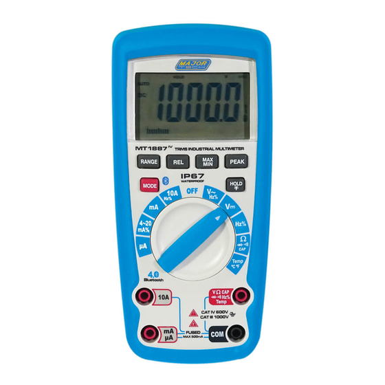
SAFETY INSTRUCTIONS This meter has been designed for safe use, but must be operated with caution. The rules listed below must be carefully followed for safe operation. 1. NEVER apply voltage or current to the meter that exceeds the specified maximum: Input Protection Limits Function Maximum Input... - Page 4 Controls and Jacks 1. 40,000 count LCD display 2. REL button 3. RANGE button 4. MODE button 5. Function switch 6. mA, µA and 10A input jacks 7. COM input jack 8. Positive input jack 9. HOLD and (Backlight) button PEAK button MAX/MIN button Note: Tilt stand and battery compartment are on rear of unit.
-
Page 5: Dc Voltage Measurements
Operating Instructions WARNING: Risk of electrocution. High-voltage circuits, both AC and DC, are very dangerous and should be measured with great care. ALWAYS turn the function switch to the OFF position when the meter is not in use. If “OL” appears in the display during a measurement, the value exceeds the range you have selected. -
Page 6: Dc Current Measurements
DC CURRENT MEASUREMENTS CAUTION: Do not make 20A current measurements for longer than 30 seconds. Exceeding 30 seconds may cause damage to the meter and/or the test leads. Insert the black test lead banana plug into the negative COM jack. For current measurements up to 4000µA DC, set the function switch to the yellow µA position and insert the red test... -
Page 7: Resistance Measurements
RESISTANCE MEASUREMENTS WARNING: To avoid electric shock, disconnect power to the unit under test and discharge all capacitors before taking any resistance measurements. Remove the batteries and unplug the line cords. ΩCAP position. Set the function switch to the green Insert the black test lead banana plug into the negative COM jack. -
Page 8: Temperature Measurements
TEMPERATURE MEASUREMENTS Set the function switch to the green Temp position. Insert the Temperature Probe into the input jacks, making sure to observe the correct polarity. indicate “ºF” or “ºC” Press the MODE button to Touch the Temperature Probe head to the part whose temperature you wish to measure. -
Page 9: Autoranging/Manual Range Selection
% 4 – 20mA MEASUREMENTS Set up and connect as described for DC mA measurements. Set the rotary function switch to the 4-20mA% position. The meter will display loop current as a % with 0mA=-25%, 4mA=0%, 20mA=100%, and 24mA=125%. Non-Contact AC Voltage Measurements WARNING: Risk of Electrocution. - Page 10 Press the REL button to store the reading in the display and the "REL" indicator will appear on the display. The display will now indicate the difference between the stored value and the measured value. Press the REL button to exit the relative mode.
-
Page 11: Display Backlight
DISPLAY BACKLIGHT Press the HOLD/ key for >1 second to turn the backlight on. the back light will flash a bright blue. The backlight will automatically turn off after 10 seconds. HOLD The hold function freezes the reading in the display. Press the HOLD key momentarily to activate or to exit the HOLD function. -
Page 12: Battery Installation
Maintenance WARNING: To avoid electric shock, disconnect the test leads from any source of voltage before removing the back cover or the battery or fuse covers. WARNING: To avoid electric shock, do not operate your meter until the battery and fuse covers are in place and fastened securely. -
Page 13: Replacing The Fuses
REPLACING THE FUSES WARNING: To avoid electric shock, disconnect the test leads from any source of voltage before removing the meter cover. Disconnect the test leads from the meter. Remove the protective rubber holster. Remove the battery cover (two “B” screws) and the battery. Remove the six “A”... - Page 14 Specifications Function Range Resolution Accuracy DC Voltage 400mV 0.01mV 0.0001V (0.06% reading + 2 digits) 0.001V 400V 0.01V (0.1% reading + 2 digits) 1000V 0.1V AC Voltage 50 to 1000Hz (1.0% reading + 4 digits) 400mV 0.1mV 0.001V 0.01V (1.0% reading + 3 digits) 400V 0.1V 1000V...
- Page 15 Function Range Resolution Accuracy (0.3% reading + 9 digits) Resistance 400 0.01 4k 0.0001k 40k 0.001k (0.3% reading + 4 digits) 400k 0.01k 4M 0.001M (2.0% reading + 10 digits) 40M 0.001M Capacitance 40nF 0.001nF (3.5% reading + 40 digits) 400nF 0.01nF 4F...
- Page 16 Enclosure Double molded, waterproof Shock (Drop Test) 6.5 feet (2 meters) Diode Test Test current of 0.9mA maximum, open circuit voltage 2.8V DC typical Continuity Check Audible signal will sound if the resistance is less than 35 (approx.), test current <0.35mA PEAK Captures peaks >1ms Temperature Sensor Requires type K thermocouple...
Need help?
Do you have a question about the MT1887 and is the answer not in the manual?
Questions and answers