Table of Contents
Advertisement
Quick Links
Advertisement
Table of Contents

Subscribe to Our Youtube Channel
Related Manuals for Major tech MT1883


Summary of Contents for Major tech MT1883
- Page 1 INSTRUCTION MANUAL MT1883 Manual Ranging Multimeter...
-
Page 2: Table Of Contents
Contents Page no 1. Safety Instructions..............3 2. Panel Descriptions..............4 3. Specifications................5 4. Operation................8 4.1. Back Light Button............... 9 4.2. DC Voltage Measurement..........9 4.3. AC Voltage Measurement...........9 4.4. DC Current Measurement..........10 4.5 .AC Current Measurement..........10 4.6. Resistance Measurement..........11 4.7. Continuity Check..............11 4.8. -
Page 3: Safety Instructions
1. Safety Instructions The following safety information must be read and understood to insure maximum personal safety during the operation of this meter: • Do not use the meter if the meter or test leads look damaged, or if you suspect that the meter is not operating properly. •... -
Page 4: Panel Descriptions
1.2 Safety Symbols This symbol adjacent to another symbol, terminal or operating device indicates that the operator must refer to an explanation in the manual to avoid personal injury or damage to the meter This WARNING symbol indicates a potentially hazardous WARNING situation, which if not avoided, could result in death or serious injury. -
Page 5: Specifications
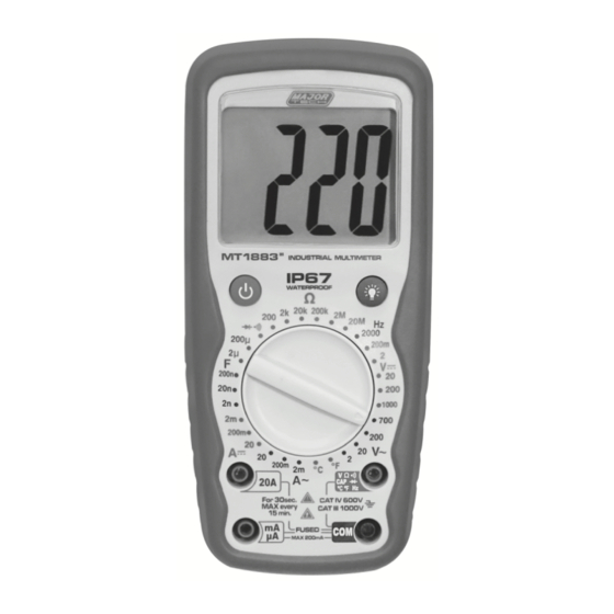
1. Large 2000 Count LCD Display - with backlight and HOLD, °C, °F, BAT symbol signs 2. Power ON/OFF Button 3. Function Switch 4. 20A (positive) input jack - for 20A DC/AC measurements 5. mA input jack - for mA DC/AC measurements 6. - Page 6 DC Voltage Range Resolution Accuracy 200.0mV 0.1mV 2.000V ±0.5% of rdg ± 2 dgts 20.00V 10mV 200.0V 100mV ±0.8% of rdg ± 2 dgts 1000V Input impedance: 10MΩ. 200mV range maximum input: 250V DC or 250V AC RMS. Maximum Input: 1000V DC or 700V AC RMS. AC Voltage Range Resolution...
- Page 7 AC Current Range Resolution Accuracy 2.000mA ±1.2% of rdg ± 3 dgts 200.0mA 100uA ±2.0% of rdg ± 3 dgts 20.00A 10mA ±3.0% of rdg ± 10 dgts Overload Protection: 0.2A/250V and 20A/250V fuse. Frequency Range: 50 to 400Hz Maximum Input: 200mA DC or 200mA AC RMS on mA ranges, 20A DC or AC RMS on 20A range.
-
Page 8: Operation
Frequency Range Resolution Accuracy 2000Hz ±1.5% of rdg ± 5 dgts Sensitivity: 200mV ~ 10V RMS Overload Protection: 250V DC or AC RMS Temperature Range Resolution Accuracy -20°C to 760°C 1°C ±3% of rdg ±5°C/9°F -4°F to 1400°F 1°F Sensor: Type-K Thermocouple Overload Protection: 250V DC or AC RMS Diode Test Test Current: 1mA typical... -
Page 9: Back Light Button
4.1. Back Light Button The back light button is used to turn the back light on only. To extend the battery life, the back light will be turned off automatically within around 3 seconds. 4.2. DC Voltage Measurements Caution: Do not measure DC voltages if a motor on the circuit is being switched ON or OFF. -
Page 10: Dc Current Measurement
4.4. DC Current Measurements Caution: Do not make current measurements on the 20A scale for longer than 30 seconds. Exceeding 30 seconds may cause damage to the meter and/or the test leads. Insert the black test lead banana plug into the negative (COM) jack. -
Page 11: Resistance Measurement
Apply power to the circuit. Read the current on the display. The display will indicate the proper decimal point value. 4.6. Resistance Measurements Warning: To avoid electric shock, disconnect power to the unit under test and discharge all capacitors before taking any resistance measurements. -
Page 12: Frequency Measurement
Reverse the probe polarity by switching probe positions. Note the reading. The diode or junction can be evaluated as follows: A. If one reading shows a value and the other reading shows “1", the diode is good. B. If both readings show “1", the device is open. C. -
Page 13: Replacing The Battery
Insert the temperature probe into the negative jack (COM) and the positive jack (Temperature), making sure to observe the correct polarity. Touch the temperature probe head to the part whose temperature you wish to measure. Keep the probe touching the part under test until the reading stabilises (about 30 seconds) Read the temperature on the display. -
Page 14: Replacing The Fuse
Note: If your meter does not work properly, check the fuses and battery to make sure that they are still good and that they are properly inserted. 7. Replacing the Fuses Warning: To avoid electric shock, disconnect the test leads from any source of voltage before removing the back cover. - Page 16 MAJOR TECH (PTY) LTD South Africa Australia www.major-tech.com www.majortech.com.au sales@major-tech.com info@majortech.com.au...
Need help?
Do you have a question about the MT1883 and is the answer not in the manual?
Questions and answers