
Subscribe to Our Youtube Channel
Related Manuals for PerfecTron OXY5741A


Summary of Contents for PerfecTron OXY5741A
- Page 1 Version 1.2 OXY5741A Ruggedised Open-Standard EBX SBC -40°C~85°C Expansion Extend Tempture www.perfectron.com...
-
Page 2: Safety Information
All rights reserved. No part of this publication may be reproduced in any form or by any means, without prior written permission from the publisher. All trademarks are the properties of the respective owners. All product specifications are subject to change without prior notice www.perfectron.com... -
Page 3: Revision History
V1.1 2021/05/27 Add Mechanical Dimensions V1.2 2021/9/10 Modify DIO Pin Define Packing list Item Description Q’ty OXY5741A EBX SBC 1 CD(Drivier + User’s manual) If any of the above items is damaged or missing, please contact your local distributor. www.perfectron.com... -
Page 4: Rohs Compliance
The task force will ensure that we follow the standard Perfectron development procedure and that all the new RoHS components and new manufacturing processes maintain the highest industry quality levels for which Perfectron are renowned. -
Page 5: Table Of Contents
3.4.7 HardwareMonitor .................................... 28 3.4.8 USB configuation....................................29 3.4.9 CSM Configuration................................... 29 3.4.10 NVMe Configuration ..................................30 3.4.11 Network Stack Configuration ..............................30 3.5 Chipset ........................................31 3.5.1 SA Configuration ....................................31 3.5.1.1 LCD Control ....................................32 3.5.2 PCH-IO Configuration ..................................32 www.perfectron.com... - Page 6 3.6 Security ........................................33 3.7 Boot …………………………………………………………………………………………………………….……33 3.8 Save & Exit......................................34 www.perfectron.com...
-
Page 7: Chapter 1 : Product Introduction
Audio Codec ALC887 Rear I/O Display Port 4 x USB 3.1 Front I/O DC Connector 6 (HDD, 2 x LAN ACT+LINK) RED/GREEN LED Power Switch 2 x USB 3.0 Internal I/O header (No Edge I/O Needed) USB2.0 GPIO Header www.perfectron.com... -
Page 8: Block Diagram
Power Type DC-IN 12V Power Consumption 250W Dimension 146 mm X 243mm -40 ℃ ~ 85 ℃ Operating Temperature Storage Temperature 40 ℃ ~ 85 ℃ Relative humidity 10% to 90%, non-condensing Standard Compliance Standard Compliance CE/FCC 1.2 Block Diagram www.perfectron.com... -
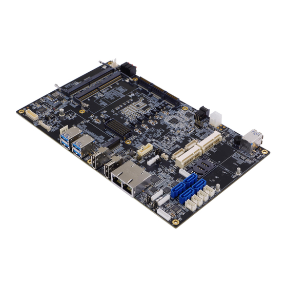
Page 9: Board Placement
1.3 Board Placement www.perfectron.com... -
Page 10: Mechanical Dimensions
1.4 Mechanical Dimensions www.perfectron.com... -
Page 11: Chapter 2 : Jumpers And Connectors Loaction
FPE Top connector STACKPC1 PCIe/104 connector LED2 LAN1 LED STATUS LED3 LAN2 LED STATUS LED4 Power/HDD LED LVDS Resolution selection Inverter connector Power Button PCIE CFG[5:6] Front Panel JCMOS1 ME Flash Security JCMOS2 RTC Reset AT/ATX Mode M.2 M KEY Connector www.perfectron.com... -
Page 12: Jumper Setting
1280*800/18bit (single) off on off off 1280*1024/24bit (dual) off on off on 1366*768/24bit (single) off on on off 1440*900/24bit (dual) off on on on 1920*1080/24bit (dual) JP1: LVDS_VDD select Jumper Function description Setting 3.3V Default setting: 2-3 www.perfectron.com... - Page 13 CN9/CN11/CN13/CN15: Serial ATA Connectors PIN DEFINITION CN10/CN12/CN14/CN16: SATA POWER Connector DEFINITION • 1 12V J2: Digital I/O Box Head PIN DEFINITION 1 DIO0(Input) 2 DIO1(Input) 3 DIO2(Input) 4 DIO3(Input) 5 DIO4(Output) 6 DIO5(Output) 7 DIO6(Output) 8 DIO7(Output) 9 3V3 10 GND www.perfectron.com...
- Page 14 3.3VAUX 1.5V CLKREQ# UIM_PWR UIM_DATA REFCLK- UIM_CLK REFCLK+ UIM_RESET UIM_VPP W_Disable# PERST# PERn0 +3.3Vaux PERp0 1.5V SMB_CLK PETn0 SMB_DATA PETp0 USB_D- USB_D+ +3.3VAUX +3.3VAUX 1.5V 3.3VAUX JP5 : AT/ATX Mode Selection, Default: 1-2 or OPEN TBD on VA2 Stage www.perfectron.com...
- Page 15 1.5V SMB_CLK PETn0 SMB_DATA PETp0 USB_D- USB_D+ 3V3_MINI2 3V3_MINI2 1.5V 3.3V LAN1: Intel I219LM LAN2: Intel I210IT LAN1 LAN2 DEFINITION DEFINITION I218_LAN1_MDI0_DP LAN2_MDIP0 I218_LAN1_MDI0_DN LAN2_MDIN0 I218_LAN1_MDI1_DP LAN2_MDIP1 I218_LAN1_MDI1_DN LAN2_MDIN1 I218_LAN1_MDI2_DP LAN2_MDIP2 I218_LAN1_MDI2_DN LAN2_MDIN2 I218_LAN1_MDI3_DP LAN2_MDIP3 A10 I218_LAN1_MDI3_DN B10 LAN2_MDIN3 www.perfectron.com...
- Page 16 USB_VCC0 USB_VCC1 USBD2- USBD3- USBD2+ USBD3+ USB_SSRX1N_C USB_SSRX2N_C USB_SSRX1P_C USB_SSRX2P_C USB3TN1 USB3TN2 USB3TP1 USB3TP2 CN4: USB3.0 *2 LOWER USB UPPER USB PIN DEFINITION PIN DEFINITION USB_VCC2 USB_VCC3 USBD0- USBD1- USBD0+ USBD1+ USB_SSRX3N_C USB_SSRX4N_C USB_SSRX3P_C USB_SSRX4P_C USB3TN3 USB3TN4 USB3TP3 USB3TP4 www.perfectron.com...
- Page 17 1 GND 2 GND 3 GND+VIN 4 GND +VIN 5 +VIN 8 +VIN 7 +VIN CN17: LPC PIN DEFINITION 1 GND 2 INT_SERIRQ 3 3.3V 4 LPC_AD0 5 LPC_AD1 6 LPC_AD2 7 LPC_AD3 8 LPC_FRAME# 9 CHIP_PLTRST# 10 CLK www.perfectron.com...
- Page 18 16 GND 17 DDID_ AUXN 18 DPD_DET 19 GND 20 DPD_PWR DP3: DISPLAY PORT HEADER PIN DEFINITION PIN DEFINITION DDI3_TXP0_DP-C DDI3_TXN0_DP-C DDI3_TXP1_DP-C DDI3_TXN1_DP-C DDI3_TXP2_DP-C DDI3_TXN2_DP-C DDI3_TXP3_DP-C DDI3_TXN3_DP-C DDI3_AUX_P_C DDI3_AUX_N_C DDI3_DDC_AUX_SEL DP3_DET DP3_PWR SIM_CARD1: SIM card socket DEFINITION RESET CLOCK DATA www.perfectron.com...
- Page 19 TXD2- RTS2- RXD- DSR- DCD- JP4: RS232/422/485 with 5V/12V selectable DEFINITION COM2P9SEL DTR- CTS- TXD- RTS- RXD- DSR- DCD- SW3 : CFG5/CFG6 CFG [6:5]: 00=1 x8, 2 x4 PCI Express. 01=Reserved. 10=2 x8 PCI Express. *11=1 x16 PCI Express. www.perfectron.com...
- Page 20 111 PEG_RXP_0 112 GND 113 PEG_RXP_2 114 GND 115 PEG_RXP_4 121 PEG_RXN_0 122 PEG_RXP_1 123 PEG_RXN_2 124 PEG_RXP_3 125 PEG_RXN_4 131 GND 132 PEG_RXN_1 133 GND 134 PEG_RXN_3 135 GND 141 PEG_TXP8 142 GND 143 PEG_TXP10 144 GND 145 PEG_TXP12 www.perfectron.com...
- Page 21 LED2: LAN1 LED STATUS LED1 Light Dark Flash 1000M 100M GREEN LINK UNLINK ACTIVITY LED3: LAN2 LED STATUS LED2 Light Dark Flash 1000M 100M GREEN Link Un-link Activity LED4: POWER/HDD LED LED2 Light Dark Flash HDD un-access HDD access www.perfectron.com...
- Page 22 PIN DEFINITION ON NO LIGHT OFF BLUE LIGHT FP1: Front Panel PIN DEFINITION PIN DEFINITION 1 HDLED+ 2 PLED+ 3 HDLED- 4 GND 5 GND 6 EC_PWR_BTN 7 EXT_RESET# 8 GND 9 NC 10 NC CN8: M.2 M Key Connector www.perfectron.com...
-
Page 23: Chapter 3 : Ami Bios Utility
When you first enter the BIOS Setup Utility, you will encounter the Main setup screen. You can always return to the Main setup screen by selecting the Main tab. There are two Main Setup options. They are described in this section. The Main BIOS Setup screen is shown below. www.perfectron.com... - Page 24 The time setting is entered in HH:MM:SS format. Note: The time is in 24-hour format. For example, 5:30 A.M. appears as 05:30:00, and 5:30 P.M. as 17:30:00. Access Level Display the access level of the current user in the BIOS. www.perfectron.com...
-
Page 25: Advanced Menu
Setting incorrect field values may cause the system to malfunction. 3.4.1 CPU Configuation This section is used to view CPU status and configure CPU parameters. www.perfectron.com... -
Page 26: Power & Performance
3.4.2 Power & Performance 3.4.3 PCH-FW Configuration www.perfectron.com... -
Page 27: Trusted Computing
Enables or Disables System ability to Hibernate (OS/S4 Sleep State). This option may be not effective with some OS. ACPI Sleep State Select the highest ACPI sleep state the system will enter when the SUSPEND button is pressed. Lock Legacy Resources www.perfectron.com... -
Page 28: It8786 Super Io Configuration
Enables or Disables Lock of Legacy Resources 3.4.6 IT8786 Super IO Configuration User can choose a mode (RS232/RS422/RS485) on Serial Port 1. Serial Port 2/3/4 only support RS232 www.perfectron.com... -
Page 29: Hardwaremonitor
Detects and displays the current CPU temperature. System Temperature Detects and displays the current system temperature. CPU Fan Speed Detects and displays the current CPU fan speed. VCORE to 1.35VDUAL Detects and displays the output voltages. www.perfectron.com... -
Page 30: Usb Configuation
3.4.8 USB configuation 3.4.9 CSM Configuration CSM Support for debug purpose CSM Support Enable/Disable CSM Support. www.perfectron.com... -
Page 31: Nvme Configuration
3.4.10 NVMe Configuration 3.4.11 Network Stack Configuration www.perfectron.com... -
Page 32: Chipset
3.5 Chipset This section is used to configure the system based on the specific features of the chipset. 3.5.1 SA Configuration www.perfectron.com... -
Page 33: Lcd Control
3.5.1.1 LCD Control 3.5.2 PCH-IO Configuration www.perfectron.com... - Page 34 To access the sub menu for the following items, select the item and press <Enter>: Change Administrator / User Password Select this option and press to access the sub menu, and then type in the password. 3.7 Boot www.perfectron.com...
- Page 35 Discard Changes and Reset Reset system setup without saving any changes. Save Options Save Changes: Save Changes done so far to any of the setup options. Discard Changes: Discard Changes done so far to any of the setup options. www.perfectron.com...
Need help?
Do you have a question about the OXY5741A and is the answer not in the manual?
Questions and answers