
Subscribe to Our Youtube Channel
Related Manuals for PerfecTron INS8367A


Summary of Contents for PerfecTron INS8367A
- Page 1 Version 1.0 INS8367A Intel® Alder Lake-S 13th /12th Processor withH610/Q670 Chipset Mini-ITX www.perfectron.com...
-
Page 2: Safety Information
All rights reserved. No part of this publication may be reproduced in any form or by any means, without prior written permission from the publisher. All trademarks are the properties of the respective owners. All product specifications are subject to change without prior notice www.perfectron.com... -
Page 3: Rohs Compliance
The task force will ensure that we follow the standard Perfectron development procedure and that all the new RoHS components and new manufacturing processes maintain the highest industry quality levels for which Perfectron are renowned. -
Page 4: Revision History
2023/06/29 First release Packing List Item Description Q’ty INS8367A CD(Drivier + User’s manual) 2 x IO Bracket(Half and Full Height) SATA Cable SATA Power Cable If any of the above items is damaged or missing, please contact your local distributor. -
Page 5: Table Of Contents
3.4.6 Serial Port 1 Configuration ............................ 24 3.4.7 Serial Port 2 Configuration ............................ 25 3.4.8 Hardware Monitor ............................... 26 3.4.9 S5 RTC Wake Settings ............................27 3.4.10Network Stack Configuration ..........................28 3.4.11NVMe Configuration ............................29 3.5 Security Page ................................30 www.perfectron.com... - Page 6 3.6 Boot Page .................................. 36 3.6.1 (List Boot Device Type) Drive BBS Priorities ....................... 37 3.7 Save & Exit Page ................................38 3.8 Event Logs .................................. 39 3.8.1 Change Smbios Event Log Setting ........................... 40 3.8.2 ViewSmbios Event Log ............................411 www.perfectron.com...
-
Page 7: Chapter 1 : Product Introduction
Intel® I219-LM GbE LAN + Intel® I225V 2.5 GbE LAN Rear I/O 2 x USB3.1 ; 2 x USB2.0 Display port 2 x DP 2(1 x GbE ; 1 x 2.5GbE) Internal I/O SATAIII USB3.1 USB2.0 1 x LVDS Display I/O 1 x Backlight connector www.perfectron.com... - Page 8 170mm x 170mm ET : -20℃ ~ 70℃ Operating Temperature UT : -40℃ ~ 85℃ Storage -40℃ ~ 85℃ Temperature Relative humidity 10% to 95%, non-condensing Standard Compliance Standart Compliance CE / FCC Windows®10 64-bit OS Support Linux(Support by request) www.perfectron.com...
-
Page 9: Block Diagram
1.2 Block Diagram www.perfectron.com... -
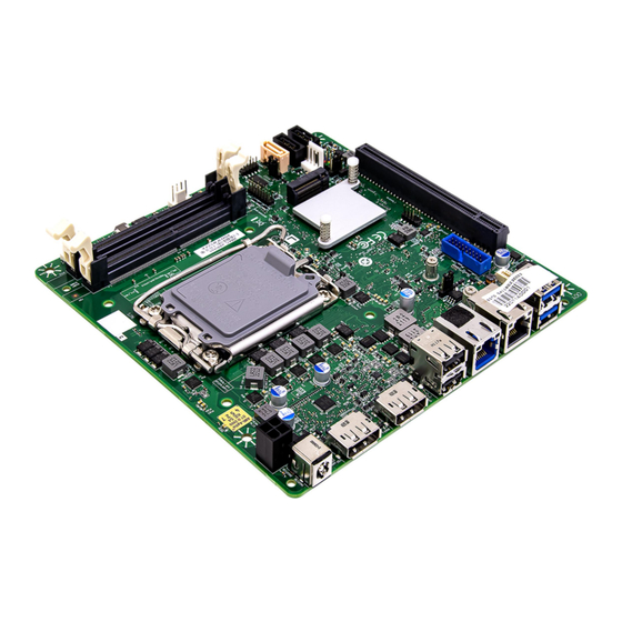
Page 10: Board Placement
1.3 Board Placement www.perfectron.com... -
Page 11: Chapter 2 : Jumpers And Connectors Loacation
SATADOM COM1 COM2 P2398 Card Header CPU FAN Header System Fan Header ATX 4pin TPM Header Clear CMOS Header AT/ATX Select Header PCIe x 16 /8 Select Header LGA1700 CPU Socket 2 x DDR4 SO-DIMM Socket M.2 2280 M-Key www.perfectron.com... -
Page 12: Jumper Settings
3 DC12V_IN 4 DC12V_IN TPM Header PIN DEFINITION PIN DEFINITION SPI_CLK 3VSB PLTRST_N 8 TPM_DET SPI_MOSI 9 TPM_PIRQ_N SPI_MISO 10 VCC3_TPM SPI_CS2_N 11 CPU/SYS FAN Header DEFINITION +12V CPU_FAN_TACH CPU_FAN_CTRL Serial Port Pin-Out(COM1/COM2) PIN DEFINITION DEFINITION RXD# TXD# Key(no pin) www.perfectron.com... - Page 13 Dip switch_GPIO43 AT/ATX Mode Jumper DEFINITION AT Mode 2-3 ATX Mode(Default) SATA Power Header PIN DEFINITION VCC(5V) INTRUDER Header PIN DEFINITION INTRUDER_N Key(no pin) Dual USB2.0 Header DEFINITION DEFINITION 5V_USB2_FP 5V_USB2_FP USB2_HR1_1N USB2_HR1_2N USB2_HR1_1P USB2_HR1_2P Key (no pin) No Connect www.perfectron.com...
- Page 14 PIN DEFINITION DEFINITION AUD_GND MIC_BIAS Presence FP_OUT_R AUD_SENSE_MIC_FP FIO_SENSE Key(no pin) FP_OUT_L AUD_SENSE_HP DMIC Header DEFINITION DMIC_DATA DMIC_CLK Key (no pin) Internal Speaker Header PIN DEFINITION LOUT- LOUT+ ROUT+ ROUT- Serial Port Pin-Out(COM2) RS422 RS485 RS232 RXD# TXD# Key(no pin) www.perfectron.com...
- Page 15 DEFINITION Pull High DFG[5]: PCI Express Bifurcation High: 1 x16 PCI Express* (Default) Low: 2 x8 PCI Express Pull Low DEFINITION 1-2 Pins 1&2 closed: High: 1 x16 PCI Express* (Default) Pins 2&3 closed: Low: 2 x8 PCI Express www.perfectron.com...
-
Page 16: Chapter 3: Ami Bios Utility
The <F10> key saves any changes made and exits the BIOS setup utility. The <Esc> key discards any changes made and exits the BIOS setup utility. Enter The <Enter> key displays a sub-screen or changes a selected or highlighted option in each menu. www.perfectron.com... -
Page 17: Main Page
Serial ATA Port 4/5/6/7 Display the installed SATA device model/size of port 4/5/6/7. System Date Set the Date. Use Tab to switch between Date elements. Default Ranges: Year: 1998-9999 Months: 1-12 Days: dependent on month. Range of Years may vary. www.perfectron.com... -
Page 18: Advance Page
0-23 mm: 0-59 ss: 0-59 3.4 Advance Page Onboard Device Onboard Device Configuration CPU Configuration CPU Configuration Parameters VMD setup menu VMD Configuration setting Trusted Computing Trusted Computing Settings NCT6126D Super IO Configuration System Super IO Chip Parameters. www.perfectron.com... -
Page 19: Onboard Device
Enable/Disable processor Turbo Mode (requires Intel Speed Step or Intel Speed Shift to be available and enabled. Disabled / Enabled State After G3 Specify what state to go to when power is re-applied after a power failure (G3 state). S0 State / S5 State www.perfectron.com... - Page 20 Enable/Disable integrated LAN to wake the system. Disabled / Enabled HD Audio Control Detection of the HD-Audio device. Disabled: HDA will be unconditionally disabled. Enabled: HDA will be unconditionally enabled. Disabled / Enabled Chassis Intrusion Configure Chassis Intrusion. Disabled / Enabled / Reset www.perfectron.com...
-
Page 21: Cpu Configuration
3.4.2 CPU Configuration Displays CPU Signature Brand String Displays the CPU brand string L3 Cache Size SMX/TXT SMX/TXT Supported or Not www.perfectron.com... -
Page 22: Vmd Setup Menu
3.4.3 VMD setup menu Enable VMD controller Enable/Disable to VMD controller. Disabled / Enabled www.perfectron.com... -
Page 23: Trusted Computing
Security Device. TCG EFI protocol and INT1A interface will not be available. Disabled / Enabled Pending operation Schedule an Operation for the ecurity Device. NOTE: Your Computer will reboot during restart in order to change State of Security Device. None / TPM Clear www.perfectron.com... -
Page 24: Nct6126D Super Io Configuration
3.4.5 NCT6126D Super IO Configuration Serial Port 1 Configuration Set Parameters of Serial Port 1 (COMA) Serial Port 2 Configuration Set Parameters of Serial Port 2 (COMB) www.perfectron.com... -
Page 25: Serial Port 1 Configuration
/ IO=228h, IRQ=3, 4, 5, 6, 7, 9, 10, 11, 12; Mode Configuration Configure serial port as RS232/RS422/RS485. 1T/1R RS422 / 3T/5R RS232 / 1T/1R RS485 TX ENABLE Low Active / 1T/1R RS422 with termination resistor / 1T/1R RS485 with termination resistor TX ENABLE Low Active / Disabled www.perfectron.com... -
Page 26: Serial Port 2 Configuration
/ IO=3E8h, IRQ=3, 4, 5, 6, 7, 9, 10, 11, 12; / IO=2E8h; IRQ=3, 4, 5, 6, 7, 9, 10, 11, 12; / IO=220h, IRQ=3, 4, 5, 6, 7, 9, 10, 11, 12; / IO=228h, IRQ=3, 4, 5, 6, 7, 9, 10, 11, 12; www.perfectron.com... -
Page 27: Hardware Monitor
Disabled / Enabled] System Fan Enable (Suppressed if Hardware Monitor Alert is Disabled) If Enabled, POST monitors system fan status. If this value is out of range, BIOS display warning message and turn on beep sound. Disabled / Enabled www.perfectron.com... -
Page 28: S5 Rtc Wake Settings
Wake up second(Show when Wake system from S5 set to Fixed Time) Select 0-59. For example enter 3 for 3am and 15 for 3pm. Wake system from S5 (when set to [Dynamic time]) Wake up minute increase Select 1-5. www.perfectron.com... -
Page 29: 10Network Stack Configuration
Enable/Disable Ipv4 PXE Boot Support. If disabled IPV4 PXE boot option will not be created. Disabled / Enabled Ipv6 PXE Support (Available when Network stack Enabled) Enable/Disable Ipv6 PXE Boot Support. If disabled IPV6 PXE boot option will not be created. Disabled / Enabled www.perfectron.com... -
Page 30: 11Nvme Configuration
3.4.11 NVMe Configuration (Device) Here shows the Device Name you installed. A sample screenshot shows below. www.perfectron.com... -
Page 31: Security Page
Press Enter when selected to go into the associated Sub-Menu. Secure Boot Set User Password. Press Enter when selected to go into the associated Sub-Menu. BIOS Update BIOS Update support Press Enter when selected to go into the associated Sub-Menu. www.perfectron.com... -
Page 32: Hdd Security Configuation
3.5.1 HDD Security configuation (Device) Read only www.perfectron.com... -
Page 33: Secure Boot
Restore Factory Keys Force System to User Mode. Install factory default Secure Boot key databases. Reset to Setup Mode Delete all Secure Boot key databases from NVRAM. Key Management Enables expert users to modify Secure Boot Policy variables without full authentication www.perfectron.com... -
Page 34: Key Management
Reset to Setup Mode Delete all Secure Boot key databases from NVRAM Platform Key (PK) Enroll Factory Defaults or load certificates from a file: 1.Public Key Certificate: a)EFI_SIGNATURE_LIST b)EFI_CERT_X509 (DER) c)EFI_CERT_RSA2048 (bin) d)EFI_CERT_SHAXXX 2.Authenticated UEFI Variable 3.EFI PE/COFF Image(SHA256) Key Source: Factory,External,Mixed www.perfectron.com... - Page 35 2.Authenticated UEFI Variable 3.EFI PE/COFF Image(SHA256) Key Source: Factory,External,Mixed Authorized TimeStamps Enroll Factory Defaults or load certificates from a file: 1.Public Key Certificate: a)EFI_SIGNATURE_LIST b)EFI_CERT_X509 (DER) c)EFI_CERT_RSA2048 (bin) d)EFI_CERT_SHAXXX 2.Authenticated UEFI Variable 3.EFI PE/COFF Image(SHA256) Key Source: Factory,External,Mixed www.perfectron.com...
-
Page 36: Bios Update
Enroll Efi Image Allow the image to run in Secure Boot mode. Enroll SHA256 Hash certificate of a PE image into Authorized Signature Database (db) 3.5.4 BIOS Update Path for ROM Image Enter the path to the BIOS update option. www.perfectron.com... -
Page 37: Boot Page
Specifies the Boot Device Priority sequence from available Hard Disk Drives. (UEFI) USB KEY Drive BBS Priorities Specifies the Boot Device Priority sequence from available Hard Disk Drives. (UEFI) USB Hard Disk Drive BBS Priorities Specifies the Boot Device Priority sequence from available Hard Disk www.perfectron.com... -
Page 38: List Boot Device Type) Drive Bbs Priorities
Drives. 3.6.1 (List Boot Device Type) Drive BBS Priorities Boot Option #1 Sets the system boot order. Boot Device Name #1 of this type / Disabled www.perfectron.com... -
Page 39: Save & Exit Page
3.7 Save & Exit Page Discard Changes and Exit Exit system setup without saving any changes. Save Changes and Reset Reset the system after saving the changes. Restore Defaults Restore/Load Default values for all the setup options. www.perfectron.com... -
Page 40: Event Logs
3.8 Event Logs Change Smbios Event Log Settings Press <Enter> to change the Smbios Event Log configuration. View Smbios Event Log Press <Enter> to change the Smbios Event Log records. www.perfectron.com... -
Page 41: Change Smbios Event Log Setting
Choose options for erasing Smbios Event Log. Erasing is done prior to any logging activation during reset. No / Yes, next reset / Yes, every reset Whea Log is Full Choose options for reactions to a full Smbios Event Log. Do Nothing / Erase Immediately www.perfectron.com... -
Page 42: Viewsmbios Event Log
3.8.2 ViewSmbios Event Log DATE / TIME / ERROR CODE / SEVERITY / COUNT Description: Log Area Reset and Count is applicable only for Multi- Events. By Events. MM/DD/YY HH:MM:SS Smbios 0x16 N/A N/A www.perfectron.com...
Need help?
Do you have a question about the INS8367A and is the answer not in the manual?
Questions and answers