Table of Contents
Advertisement
Quick Links
Advertisement
Table of Contents

Related Manuals for urmet domus UFO 12M


Summary of Contents for urmet domus UFO 12M
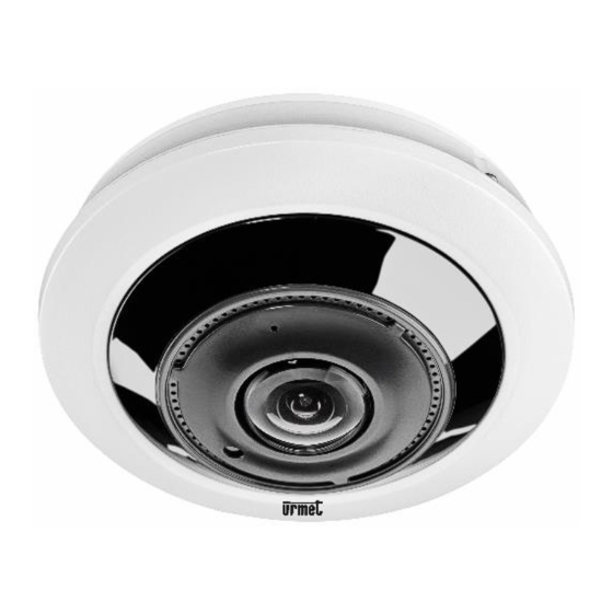
- Page 1 Mod. 1099 DS1099-168 IP H.265+ Fish Eye Camera UFO 12M Ref. 1099/680 USER MANUAL...
-
Page 2: Table Of Contents
ENGLISH LIST OF CONTENTS Introduction ..............................4 Product Description ..........................5 Technical features ........................5 Opening the Box ........................6 Warnings ...........................6 Overview ..............................8 Range of Application .........................8 Product description ........................8 Operating environment ......................9 Device Connection ............................9 IP Camera Connector Layout (Where Present) ..............10 Operating instructions ........................... - Page 3 11.5.1 Disk ................................53 11.5.2 Audio................................54 11.5.3 Cloud ................................55 11.6 System ............................ 56 11.6.1 General ............................... 56 11.6.2 User Configuration ............................57 11.6.3 Maintenance ............................... 57 11.6.3.1 Log ................................57 11.6.3.2 Load Default ............................58 11.6.3.3 Upgrade ..............................58 11.6.3.4 Parameter Management ..........................
-
Page 4: Introduction
INTRODUCTION Thank you for purchasing our integrated and developed network camera products for network video monitoring. Our range includes the following products: Storage Network Bullet, Wireless Storage Network Bullet, IR Network Dome, IR Network Weather-Proof and High-Speed Network Ball, fisheye cameras. High-performance single SOC chips are used in the media processor for audio/video acquisition, compression and transmission/transfer. -
Page 5: Product Description
PRODUCT DESCRIPTION URMET S.p.A Ref. 1099/680 is 12MegaPixel IP camera that can be controlled via a TCP/IP network connection. TECHNICAL FEATURES ➢ High-performance Sigma Star media processor with advanced functions. ➢ CMOS Progressive Sensor ➢ Optimized H.265+/H.265/H.264+/H.264 video compression algorithms; multi-stream transmission ensures high definition image transmission on both narrowband and wideband. -
Page 6: Opening The Box
OPENING THE BOX Check that the packaging and the contents are not visibly damaged. Contact the retailer immediately if parts are either missing or damaged. Do not attempt to use the device in this case. Send the product back in its original packaging if damaged. - Page 7 ➢ Make a test recording before using the device to ensure that is working correctly. Please note that URMET S.p.A. is not liable for any loss of stored data or damage caused by incorrect installation, improper use or malfunctioning of the device. ➢...
-
Page 8: Overview
OVERVIEW RANGE OF APPLICATION These network cameras with their powerful image processing capacity can be used in various public places, such as malls, supermarkets, schools, factories and workshops, as well as in environments requiring HD images, such as banks and traffic control systems, as illustrated in the figure below: Monitoring centre PRODUCT DESCRIPTION... -
Page 9: Operating Environment
OPERATING ENVIRONMENT Operating system: Windows 7/Windows 8/Windows 2008 (32/64-bit), Windows 2003/Windows XP/Windows 2000 (32-bit) or higher CPU: Intel Core Duo II processor or higher Memory: 1G or higher Video memory: 256M or higher Display: 1024 × 768 or higher resolution DEVICE CONNECTION The IP camera can be connected in two ways: •... -
Page 10: Ip Camera Connector Layout (Where Present)
IP CAMERA CONNECTOR LAYOUT (WHERE PRESENT) LAN (Network Interface): Connector for a RJ45 network cable. ALARM IN/OUT: Including alarm input and output interface. ①, ② as input alarm interface setting, ③, ④ for output alarm setting DC 12V: Power Interface RESET: The device will restore the default settings if this button is pressed and held for 3 seconds. -
Page 11: Device Searching
DEVICE SEARCHING • Feedback: The Device Config Tool function can be used for device searching across network segments. Before using Device Config Tool, click on the local connection icon in the bottom right corner of the desktop; • Add IP addresses of several network segments in the TCP/IP setting for local connection (as shown below). You can run this tool to search for any device with an IP address in the same network segment. -
Page 12: Installation Of Controls And Login To System
INSTALLATION OF CONTROLS AND LOGIN TO SYSTEM Before using the IE (Internet Explorer) browser to access the IP camera for the first time, the plug-in components must first be installed, as follows: Access the IP address of the IP camera to automatically download the controls from it. Select an option in the plug-in installation pop-up dialogue box to run the installation process. -
Page 13: Preview
using the password recovery function ➢ Certificate of authorisation: it will be possible to export a certificate (to be noted down and kept in a safe place), which in the event of loss of the password, can be used to set it again using the password recovery function ➢... -
Page 14: Live
LIVE Some of the buttons in the preview frame are described below. : Button for setting the hue, brightness, contrast, saturation and sharpness of the frame. : Reads the recording file from the SD card and plays it back through the browser. : Access to the device settings menu to customise the settings of various parameters. -
Page 15: Fish Eye Functions (Live And Playback)
FISH EYE FUNCTIONS (LIVE AND PLAYBACK) 8.1.1 TYPES OF INSTALLATION From the LIVE screen it is possible to specify the type of camera installation ("Installation Method"): on the ceiling, on a wall, on a horizontal surface or an inclined surface. 8.1.2 DISPLAY The LIVE Display Methods currently shown on the PC can be changed, depending on the type of installation selected:... - Page 16 VR view, double click with the right mouse button to begin navigation; 3D Cylinder, as shown in the figure: 2PTZ, as shown in the figure: DS1099-168...
- Page 17 4PTZ, as shown in the figure 180° Panorama view, as shown in the figure: 360° Panorama view, as shown in the figure: 360° Panorama View + 1PTZ (Panorama View, the different coloured area represents different PTZ viewing angles, select the range of the corresponding PTZ line and drag to change the viewing angle, as shown in the figure): DS1099-168...
- Page 18 360° Panorama View + 3PTZ (Panorama View, the different coloured areas represent different PTZ viewing angles, select the range of the corresponding PTZ line and drag to change the viewing angle, as shown in the figure): 360° Panorama View + 6PTZ (Panorama View, the different coloured areas represent different PTZ viewing angles, select the range of the corresponding PTZ line and drag to change the viewing angle, as shown in the figure): DS1099-168...
- Page 19 360° Panorama View + 8PTZ (Panorama View, the different coloured areas represent different PTZ viewing angles, select the range of the corresponding PTZ line and drag to change the viewing angle, as shown in the figure): Fisheye + 3PTZ (Fisheye View, the different coloured areas represent different PTZ viewing angles, select the range of the corresponding PTZ line and drag to change the viewing angle, as shown in the figure): DS1099-168...
- Page 20 Fisheye + 8PTZ (Fisheye View, the different coloured areas represent different PTZ viewing angles, select the range of the corresponding PTZ line and drag to change the viewing angle, as shown in the figure): DS1099-168...
-
Page 21: Wall Installation
8.1.4 WALL INSTALLATION The fisheye camera is mounted on the ceiling on the scene. There are 7 display methods, as shown in the figure: VR view, double click with the right mouse button to begin navigation; DS1099-168... - Page 22 Standard Panorama view, as shown in the figure: 4PTZ Panorama View + 3PTZ (Panorama View, the different coloured areas represent different PTZ viewing angles, select the range of the corresponding PTZ line and drag to change the viewing angle, as shown in the figure): DS1099-168...
- Page 23 Panorama View + 8PTZ (Panorama View, the different coloured areas represent different PTZ viewing angles, select the range of the corresponding PTZ line and drag to change the viewing angle, as shown in the figure): Fisheye + 3PTZ (Fisheye View, the different coloured areas represent different PTZ viewing angles, select the range of the corresponding PTZ line and drag to change the viewing angle, as shown in the figure): DS1099-168...
-
Page 24: Installation On A Horizontal Surface
Fisheye + 8PTZ (Fisheye View, the different coloured areas represent different PTZ viewing angles, select the range of the corresponding PTZ line and drag to change the viewing angle, as shown in the figure): 8.1.5 INSTALLATION ON A HORIZONTAL SURFACE The fisheye camera is mounted on a horizontal surface/table, there are 11 viewing methods, as shown in the figure DS1099-168... - Page 25 VR view, double click with the right mouse button to begin navigation; 3D Cylinder view, as shown in the figure: DS1099-168...
- Page 26 4PTZ, as shown in the figure: 180° Panorama view, as shown in the figure: 360° Panorama view, as shown in the figure: DS1099-168...
- Page 27 360° Panorama View + 1PTZ (Panorama View, the different coloured area represents different PTZ viewing angles, select the range of the corresponding PTZ line and drag to change the viewing angle, as shown in the figure): 360° Panorama View + 3PTZ (Panorama View, the different coloured area represents different PTZ viewing angles, select the range of the corresponding PTZ line and drag to change the viewing angle, as shown in the figure): DS1099-168...
- Page 28 360° Panorama View + 6PTZ (Panorama View, the different coloured area represents different PTZ viewing angles, select the range of the corresponding PTZ line and drag to change the viewing angle, as shown in the figure): 360° Panorama View + 8PTZ (Panorama View, the different coloured area represents different PTZ viewing angles, select the range of the corresponding PTZ line and drag to change the viewing angle, as shown in the figure): DS1099-168...
- Page 29 Fisheye + 3PTZ (Fisheye View, the different coloured areas represent different PTZ viewing angles, select the range of the corresponding PTZ line and drag to change the viewing angle, as shown in the figure): Fisheye + 8PTZ (Fisheye View, the different coloured areas represent different PTZ viewing angles, select the range of the corresponding PTZ line and drag to change the viewing angle, as shown in the figure): DS1099-168...
-
Page 30: Installation On An Inclined Plane
8.1.6 INSTALLATION ON AN INCLINED PLANE The fisheye camera is installed on the scene which is about 25° from the vertical. There are 7 display methods, as shown in the figure: VR view, double click with the right mouse button to begin navigation; DS1099-168... - Page 31 Standard Panorama view, as shown in the figure: 4PTZ and Panorama View + 3PTZ (Panorama View, the different coloured areas represent different PTZ viewing angles, select the range of the corresponding PTZ line and drag to change the viewing angle, as shown in the figure): DS1099-168...
- Page 32 Panorama View + 8PTZ (Panorama View, the different coloured areas represent different PTZ viewing angles, select the range of the corresponding PTZ line and drag to change the viewing angle, as shown in the figure): Fisheye + 3PTZ (Fisheye View, the different coloured areas represent different PTZ viewing angles, select the range of the corresponding PTZ line and drag to change the viewing angle, as shown in the figure): DS1099-168...
- Page 33 Fisheye + 8PTZ (Fisheye View, the different coloured areas represent different PTZ viewing angles, select the range of the corresponding PTZ line and drag to change the viewing angle, as shown in the figure): DS1099-168...
-
Page 34: Local Settings
LOCAL SETTINGS Select Local Settings to display the following dialogue box: in it you can set the video storage location, paths for downloading the remote file and store the snapshot, the file type (RF by default, with AVI or MP4), video recording duration and capture type (BMP. -
Page 35: Playback
10 PLAYBACK Select Playback in Record File to top right of the main screen to access the video and image search page. There are four search modes, general, picture and tag. General search mode: Explanation of the button functions: Type of recording file: ALL, Normal, Event. Normal: 24H recording Event: IO alarms, Sound detection, Netbreak and Motion. - Page 36 Picture search mode: Set the date, time and choose the search type from All, Normal, Event (I/O and/or Motion). Press on Search to start the image search. Tag search mode: Set the start and end date/time of the search and possibly enter a keyword for the search in the Keyword field. Press on Search to start the tag search.
-
Page 37: Remote Setting
11 REMOTE SETTING 11.1 DISPLAY CONFIGURATION 11.1.1 LIVE Select Remote Settings to open the page shown below (default preview setting page): Name: Name of the IP camera. Date Format: Choose the desired date format from MM/DD/YYYY, YYYY-MM-DD or DD/MM/YYYY. Time Format: Choose the desired time format from 24-hour or 12-hour. Flicker control: Choose 50Hz or 60Hz. -
Page 38: Image Control
11.1.2 IMAGE CONTROL Select Image Control in Channel to open the following page: IR-CUT Mode: Automatic mode, Color mode, Black-White mode, Imagine mode and Schedule. Setting Schedule you can choose the start and end time of the IR-Cut IR-CUT Delay: IR-cut switching delay. IR-LED: You can choose between Manual and Smart IR. -
Page 39: Video Cover (Privacy Zone)
11.1.3 VIDEO COVER (PRIVACY ZONE) Select Privacy Zone in Channel Configuration to open the following page: Enable Video Cover, and then use the right mouse button to trace rectangles around areas not to be displayed during recording, in screenshots and in Live viewing. Save when done to keep the settings. -
Page 40: Record Parameters
11.2 RECORD PARAMETERS 11.2.1 ENCODE Select Encode in the menu Record to access the page below The following streams are available by default: • Main stream, Sub stream and Mobile stream: The resolution, Frames per second, video encoding type, encoding level, bitrate control, bitrate mode, bitrate frequency, I Frame interval, audio can be set for the Main stream, Sub stream and Mobile stream respectively. -
Page 41: Record
11.2.2 RECORD Select Record in the Record menu to access the following page. This function allows you to control recording, pre-recording, recording type (main stream and secondary stream) and automatic recording on SD card in case of network failure (Netbreak). 11.2.2.1 Schedule Select Schedule in the menu Record to access the page below. -
Page 42: Event
Capture Schedule This item allows you to configure the time slots and days of the week when the capture function is to be operational. Normal: When the time slot is marked in green, this indicates that the channel performs normal recording in that time slot. Motion: When the time slot is marked in yellow, this indicates that the channel only performs recording if motion is detected in that time slot. -
Page 43: Siren
11.3.1.2 Siren • Siren: enables the siren in the event of a detected event. • Siren Level: The intensity of the siren sound can be set on a scale of 1 to 10. • Siren Duration: You can set the duration (in seconds) of the siren sound in case of an event on a scale from 5 to 180. -
Page 44: Alarm
NOTE: ➢ Sending push notifications is not available for the sound detection event using the Camera connected alone. If you wish to receive push notifications on the App for this type of event, it is necessary to associate and connect the IP Camera to the NVR/HVR. 11.3.2 ALARM 11.3.2.1... -
Page 45: I/O
11.3.2.2 Alarm Type: OFF, Normally-Open, Normally-Close. Latch Time: Set the alarm output time (5S,10S, 20S, 30S). [for models where applicable]. Post Recording: After checking Enable Record, you can set the recording delay (5S, 10S, 20S, 30S). Send Mail: function used with SMTP, to enable the sending of mails. FTP Picture Upload: Enables or disables sending pictures to an FTP Server. -
Page 46: Sound Detection
11.3.2.3 Sound Detection Alarm Type: OFF, Normally-Open, Normally-Close. Latch Time: Set the alarm output time (5S,10S, 20S, 30S). [for models where applicable]. Post Recording: After checking Enable Record, you can set the recording delay (5S, 10S, 20S, 30S). Send Mail: function used with SMTP, to enable the sending of mails. FTP Picture Upload: Enables or disables sending pictures to an FTP Server. -
Page 47: Event Push
11.3.3 EVENT PUSH In this section, you can enter the server on which to receive Push notifications. Enable: Enables the functionality of sending PUSH to an HTTP or UDP server. Name: Enter the name of the server. Push Way: Choose the server type between HTTP and UDP server. -
Page 48: Pppoe
: The Test button allows a check to be made that the device is correctly addressed on the network. Subnet Mask: This is a network parameter that defines a range of IP addresses that can be used on a network. Assuming that the IP address represents the street where you live, the subnet mask is the neighbourhood. -
Page 49: Snmp
11.4.1.3 SNMP (For future use) SNMP: Simple Network Manage Protocol, an open source protocol. SNMP can check basic device parameters such as IP, hardware information and software information. 11.4.1.4 Port Configuration HTTP Port (Web Port): This is the port that will be used to connect remotely with the camera (i.e., via the Web Client). If the default port 80 is already being used by other applications, it must be changed. -
Page 50: E-Mail Configuration
11.4.2 E-MAIL CONFIGURATION Select E-Mail in the Network menu to open the following e-mail service setup page - used with the alarm function to send images to the mail server: E-Mail: Service enabling/disabling. Encryption: The options are Deactivate/SSL/TLS/AUTO. SMTP Port: The default port number is 25. SMTP server: Enter the address of the mail server. -
Page 51: Ftp
11.4.3 This menu enables the FTP function to display and upload snapshots captured by the camera to the storage device on FTP. FTP Enable: select the desired option to enable or disable operation. IP Server: Enter the address or name of the FTP server. -
Page 52: Https
11.4.6 HTTPS In this menu, the security encryption protocol can be set. Certificate Type: Default or Custom 11.4.7 IP FILTER Select IP Filter in the Network menu to open the following page: Enable: by ticking Enable, the Whitelist and Blacklist can be configured. Type: Enable Allow List or Enable Block list Restricted Type: Select the type of restriction to be configured It is possible for both lists to add one address, Single Add, or a list of addresses, Network Segment Add. -
Page 53: Device
It is possible to edit the address list from the Edit button, or delete the list from the Delete button. Press Save to save the desired setting. 11.5 DEVICE This includes SD Card, Audio and Cloud. The various interfaces and functions are described below. 11.5.1 DISK Select Disk in the Device menu to access the page below. -
Page 54: Audio
11.5.2 AUDIO Click on Audio in the Device menu to open the following page: Audio setup procedure: Check the Enable Audio option to access audio settings, and set the audio input/output volume (range 0~10), and then select Save to save the parameters set. (Note: To be able to use the audio function, the audio option in Video Streaming needs to be enabled). -
Page 55: Cloud
11.5.3 CLOUD The IP Camera is able to transfer video in the event of an alarm, to a Cloud storage service via Dropbox, a free service that allows snapshots to be easily stored and shared, and to always have them to hand when needed. Configuration is accessible via the Cloud item in the DEVICE menu. -
Page 56: System
11.6 SYSTEM System parameters include: General, Multi-Users, Maintenance, Information. The various interfaces and functions are described below. 11.6.1 GENERAL Click on General in the System menu to open the following page: The device time, system time and date/time format contained in the basic information can be manually set and saved. Three automatic time setting functions are provided in this device. -
Page 57: User Configuration
11.6.2 USER CONFIGURATION Click on Multi-User in the System menu to open the following page: In this section you can set the user access authority and login password 11.6.3 MAINTENANCE In this section, it is possible to search and view the log (system, configuration, user, logging, memory, network), load default settings, update the system, export/import system parameters and manage automatic system restart. -
Page 58: Load Default
11.6.3.2 Load Default Through this menu, the camera's factory settings can be reset. You can choose to reset all settings at once or only specific menu settings. Resetting to factory settings will not delete recordings and snapshots saved on SD. Select all entries to be reset or tick All to select all entries. -
Page 59: Auto Reboot
11.6.3.5 Auto Reboot This menu enables the system to automatically reboot the camera periodically. Auto-maintenance (Auto-restart): Click to enable the function Time: You can set the day, week or month to restart the camera. Press Save to save the desired setting. 11.6.4 SYSTEM INFORMATION Select Information in the System menu to open the following page:... -
Page 60: Fisheye Ip Camera Technical Specifications
12 FISHEYE IP CAMERA TECHNICAL SPECIFICATIONS Description UFO 12M Function 1099/680 Image Sensor 1/2.3" Progressive CMOS Sensor Type OV12895 Color 0.01lux @ F1.6(AGC ON) Minimum Luminance B/W 0 lux @ IR ON Lens Mount/Lens Type Fish Eye Viewing angle H.FOV: 360°... - Page 61 Description UFO 12M Function 1099/680 Internet Explorer 11.0 for Windows 7 and higher/ Edge / Firefox Mozilla / Google Chrome / Safari 6.0 Urmet UVS pro Client Support: Windows 7 O.S. or higher / MAC O.S. 10.8.0 or higher Mobile Support Software: (iOS, Android)
-
Page 62: Maximum Recording Time With Sd Card
13 MAXIMUM RECORDING TIME WITH SD CARD 13.1 REF. 1099/680 The following resolution options can be selected for Main Stream recording: “12Mpx”, “9Mpx”, “5Mpx”, “4Mpx”, “3Mpx”, “1080P”, “720P” for IP camera with coding H.265+ / H.265 / H.264+ ➢ / H.264 IMPORTANT NOTES ➢... -
Page 63: Appendix
14 APPENDIX 14.1 ROUTER PORT FORWARDING To remotely view the IP Camera via the Internet, you must first set the web port and client port of the IP Camera. Taking a Cisco router as an example: The IP address of the IP camera is 192.168.1.168, the web port is 8000 and the client port is 9988. DS1099-168... -
Page 64: Frequently Asked Questions
14.2 FREQUENTLY ASKED QUESTIONS ◆ Internet Explorer cannot load and install plug-ins. Possible cause: IE security levels are set too high. Solution: Set IE security levels to the minimum value. ◆ After updating, it is not possible to access the IP Camera through Edge in Internet Explorer mode. Solution: Clear the IE cache as follows: open IE Tools, select Internet Options, select the 2nd option under “Delete Files”... - Page 65 DS1099-168 Engineering Dept. URMET S.p.A. customer service +39 011.23.39.810 10154 TURIN (ITALY) http://www.urmet.com VIA BOLOGNA 188/C e-mail: info@urmet.com Tel. +39 011.24.00.000 (AUTO) MADE IN CHINA +39 011.24.00.300 - 323 DS1099-168...
Need help?
Do you have a question about the UFO 12M and is the answer not in the manual?
Questions and answers