
Related Manuals for urmet domus 1099/214B


Summary of Contents for urmet domus 1099/214B
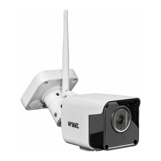
- Page 1 Mod. 1099 DS1099-160 WIFI 3MP IP PoE CAMERAS SERIES BULLET 1099/214B 1099/216B USER MANUAL...
-
Page 2: Table Of Contents
Warnings ............................4 SIMPLIFIED EU DECLARATION OF CONFORMITY .................. 5 INSTALLATION ............................. 5 1099/214B→ WiFi Bullet fixed lens camera................. 5 1099/216B → WiFi Bullet Varifocal camera ................. 6 HOW TO CONFIGURE THE CAMERA IN A NETWORK................6 How to add the camera to a WiFi network from the App ............. 6 How to add the camera to a WiFi network using a smartphone browser ........ -
Page 3: Introduction
Care if you encounter problems during operations. The manual will be regularly updated without prior notice. PRODUCT DESCRIPTION URMET devices Ref. 1099/214B, Sch. 1099/216B are wireless IP cameras which may be controlled entirely by connecting to the TCP/IP network. Technical specifications ➢... -
Page 4: Warnings
WARNINGS Power ➢ Make sure that the rating plate data corresponds to the power specifications before connecting the device to the mains. ➢ Arrange a suitable circuit breaker and fuse upstream of the devices. ➢ Disconnect power by means of the circuit breaker in the event of a failure and/or bad operation. Safety precautions ➢... -
Page 5: Simplified Eu Declaration Of Conformity
IMPORTANT NOTE: the camera loses network configuration and the WiFi interface returns to Access Point mode. SIMPLIFIED EU DECLARATION OF CONFORMITY Hereby, URMET S.p.A. declares that the radio equipment types: cameras 1099/214B, 1099/216B, are in compliance with Directive 2014/53/EU. The full text of the EU declaration of conformity is available at the following internet address: www.urmet.com... -
Page 6: 1099/216B → Wifi Bullet Varifocal Camera
1099/216B → WIFI BULLET VARIFOCAL CAMERA It is advisable to proceed as follows for correct camera installation and configuration: Make sure that no units are powered before starting the installation procedure. Fit the aerial on the camera. It is advisable to install and configure one camera at a time if you are installing multiple cameras on the same network. -
Page 7: How To Add The Camera To A Wifi Network Using A Smartphone Browser
Alternatively, the camera can be also configured on the WiFi network without making use of the smartphone, i.e. using a PC in either way: by temporarily wiring the camera to the LAN (see § 4.4) or in ACCESS POINT mode (see § 4.5). HOW TO ADD THE CAMERA TO A WIFI NETWORK USING A SMARTPHONE BROWSER The camera can be easily configured on the WiFi network using the smartphone browser: Open the WiFi settings of the smartphone and select the SSID of the camera in AP (Access Point) mode, the SSID is of the... - Page 8 Once the smartphone is connected to the camera's Wifi, using any smartphone browser, open the camera's web page at the address http://223.223.100.1 by logging in with User Name: admin, Password: admin Search After logging in, the Wi-Fi management page of the camera opens directly, pressing the button displays the list of Wi-Fi networks detected by the camera.
- Page 9 Select the Wi-Fi corresponding to the internet router to which you want to connect the camera and enter the router's Wi-Fi Save Saved! network password, then press and wait for the message lower in the page: DS1099-160...
-
Page 10: How To Add The Camera To A Cabled Network And Connect From The App
At this point the smartphone automatically gets disconnected from the camera which is no longer in AP (Access Point) mode, the camera is therefore connected to the internet router. IMPORTANT: from factory settings the camera works in DHCP mode therefore it automatically receives a dynamic IP address assigned by the router. - Page 11 See the applicable section in the complete manual if installation of an ActiveX component is required. You can select user name (default: admin), password (default: admin), stream type (Main/Sub Stream) and language on the login page. At this point, select “Login” to open the LIVE page. Select the “Remote Setting”...
-
Page 12: How To Add The Camera To A Wifi Network Using Ap Mode And Pc
Select the SSID of the WiFi network you want to connect the camera to, enter the network key and save the configuration by pressing the “Save” button. It is advisable to check that the WiFi signal received by the camera is higher than or equal to 60. -
Page 13: Easytool
Press the “Refresh List” button of “EasyTool” to refresh the list and view the camera with the changes made. IMPORTANT NOTE: to set/edit the network parameters of the camera (IP address, subnet mask, gateway) it is advisable to use EasyTool or the web page of the camera. It is not advisable to set/edit the network configurations of the camera in the NVR/HVR menus on which the camera was added;... -
Page 14: Activex Control Configuration
ACTIVEX CONTROL CONFIGURATION You will need to install the plug-ins when inspecting the IP camera using Internet Explorer (Edge running in IE mode) for the first time. Set the browse protection level to install the plug-in. Select the menu [Tools/Internet Options/Security/Custom Level] and for "ActiveX controls and plug-ins"... -
Page 15: Connection From Other Web Browsers
CONNECTION FROM OTHER WEB BROWSERS The camera web page can be accessed using a browser other than Internet Explorer, simply by keying in the IP address of the camera on the navigation bar of the browser. In this case, no additional components need to be installed and the displayed stream live consists in MJPEG video stream for which selecting Main/Sub is not effective on the login home page. -
Page 16: Playback
Other Live interface buttons (on Internet Explorer with ActiveX only): : this is used to search and playback the video files recorded in the camera’s SD memory card (not included). : This is used to access the device setup menu to set the various customised parameters; : Snapshot, file type, saving path etc.;... -
Page 17: Remote Settings
REMOTE SETTINGS 8.3.1 DISPLAY OSD CONFIG Click on (Remote settings) to access the Live interface OSD Config (default). ➢ Name: IP camera name. ➢ Channel Display: Enable/Disable. The display position can be customised. ➢ Time Display: Enable/Disable. The display position can be customised. ➢... - Page 18 ➢ IRCUT Mode: 3 modes: GPIO & Video Mode : default mode. The camera switches from colors to black and white (turning on the IR LEDs) and vice versa based on the environment light detected by the external sensor integrated in the camera. Color Mode or Daytime: fixed setting as colors only, it never switches to B/W picture.
-
Page 19: Network
8.3.2 NETWORK Network configuration Click on 【Network】→【Network Setting】 to access the following network page. This page can be used to display and set the parameters related to the LAN of the camera: ➢ Type: DHCP, Static or PPoE. The default setting is DHCP. ➢... - Page 20 Video Stream Click on 【Network】→【Video Streaming】 to access the following interface. ➢ Type: MainStream, SubStream. ➢ The user can set: Resolution, FPS, Audio (if the camera model has audio input), Bitrate control: CBR/VBR and the MainStream/SubStream Bitrate value. ➢ Resolution: MainStream 3MP (2304x1296), 1080P(1920x1080), 720P (1280×720), SubStream (640×360). ➢...
- Page 21 Description: • IP: to be replaced with the actual IP address of the device • The JPEG snapshot resolution can be modified in the following section: 【Advanced】→【Snapshot Settings 】 Wireless Click on 【Network】) →【Wireless】 to access the following interface. Press the “Search” button to open the following page showing all the available WiFi networks and the signal power detected for each one: Select the SSID of the WiFi network you want to connect the camera to, enter the network key and save the configuration by pressing the Save button.
- Page 22 Click on 【Network】) →【Email】 to access the following interface. ➢ Server: it supports IP address or domain string Email Click on 【Network】) →【Email】 to access the following interface DS1099-160...
- Page 23 Email service setting. By using this function in association with the Motion alarm function, the camera can sent the images acquired by email on the Internet by contacting the set email server (SMTP). SMTP Port: The default value is 25 (email service port). If Email: Disable/Enable.
- Page 24 7) P2P Click on 【Network】) →【P2P】 to access the following page. P2P refers to the functionality that makes the device available for connections from remote software and app through the Internet, without any port-forwarding/virtual server setting in the router. Description •...
-
Page 25: Alarm
8.3.3 ALARM AI SETTING Click on 【Alarm】→【AI Setting】 to access the following interface. Setting Procedure 1. Enable/disable person detection (Human) and/or motion detection (Motion). 2. While holding down the left button, drag the mouse to select the person and/or motion detection area. It is also possible to choose polygonal-shaped areas (triangle, pentagon, hexagon, etc.) as shown opposite the image. - Page 26 PROGRAMMING Click on 【Alarm】) →【Schedule】 to access the following interface. Schedule: in this page it is possible to program when the alarm must be activated (All Day, User_defined). When 【User_defined】is selected, holding the left button pressed, drag the mouse to select the programming periods. Single cells can be enabled by clicking on each of them.
-
Page 27: Record
OVERLAY SETTING Click on 【Alarm】→【Overlay Setting】 to access the following interface. Main Stream: if the boxes are ticked, this enables the display of video analysis lines on identified persons and/or areas enabled on the main video stream (Main Stream). Sub Stream: if the boxes are ticked, it enables the display of video analysis lines on identified persons and/or enabled areas on the secondary video stream (Sub Stream). -
Page 28: System
8.3.5 SYSTEM The System menu contains the following items: 【Date/Time】,【Users】, 【Info】 and 【Log】. The respective interfaces and descriptions are shown below. 1) DATE/TIME SETTING Click on 【System】→【Date/Time】 to access the following interface. PARAMETERS: the Device Name can be changed here. DATE/TIME: this user interface can be used to set the date and time, including System Time, NTP, Date Format and Time Format. - Page 29 USERS Click on 【System】→【Users】 to access the following interface. New users can be created, activated and deactivated and the password can managed here. DS1099-160...
- Page 30 INFO Click on 【System】→【Info】 to access the following interface. When an SD memory card is plugged into the camera’s slot, it is possible: ➢ To read the information about total and available memory space ➢ To format the memory card by pushing the button ➢...
-
Page 31: Advanced
8.3.6 ADVANCED The options are present: 【Audio Setting】,【Snapshot Setting】,【Periodic Capture】,【Firmware Update】, 【Load Default】, and 【Maintenance】 as shown in the figure below. Audio Setting Microphone and audio input sound settings. ➢ Audio Type: you can choose the type of audio. ➢ Audio Codec: The managed audio codec is the G711U. - Page 32 Time Capture The following settings refer to periodic saving of images on local micro SD memory or FTP server. Firmware upgrade Click on 【Advanced】→【Firmware Update】 to access the following interface. In the “Firmware Update”, the user can click on "Scan" to select the update file; click on Upgrade to update the system automatically.
- Page 33 Load Default Click on 【Advanced】→【Load Default】 to access the following interface. Select “Reset factory settings” and press the Save button to restore all default setting except for: network parameters (LAN and Wireless), user Password, NTP, DST, channel name. Select “Full Reset factory settings” and press the button Save to restore the factory default settings. Click on “Reboot”...
-
Page 34: Local Settings
LOCAL SETTINGS Click on “Local Setting” to view the following dialogue window. The user can set Local Disk, Record Path, Snapshot path, file type and Interval for recording and manual snapshot capturing. IMPORTANT: to make the local settings effective, especially to create the Record and Snapshot Path folders and to save Record Files and Snapshots, IE has to be executed with Windows Andministrator privileges. -
Page 35: Technical Specifications
TECHNICAL SPECIFICATIONS GENERAL DATA 1099/214B 1099/216B Max absorption Typ: 170mA(D), 450mA(N). Peak 470mA (when IR CUT moves D/N). Power supply 12 Vdc / PoE Dimensions (L x H x D) 167*66.55*70.5mm 189*76*68mm Weight (g) 470g 650g Type of housing Bullet... -
Page 36: 10 Appendix
YES, Max 128GB included) LAN type RJ45 10M / 100M Ethernet Connector RJ45 waterproof 1099/214B 1099/216B 10 APPENDIX 10.1 FAQ ◆ IE does not load or install the plug-ins. Possible cause: The IE protection setting is too high. Solution: Set IE protection to minimum level.
Need help?
Do you have a question about the 1099/214B and is the answer not in the manual?
Questions and answers